manuals.online logo
Brands
  1. Home
  2. •
  3. Brands
  4. •
  5. Orion
  6. •
  7. Water Pump
  8. •
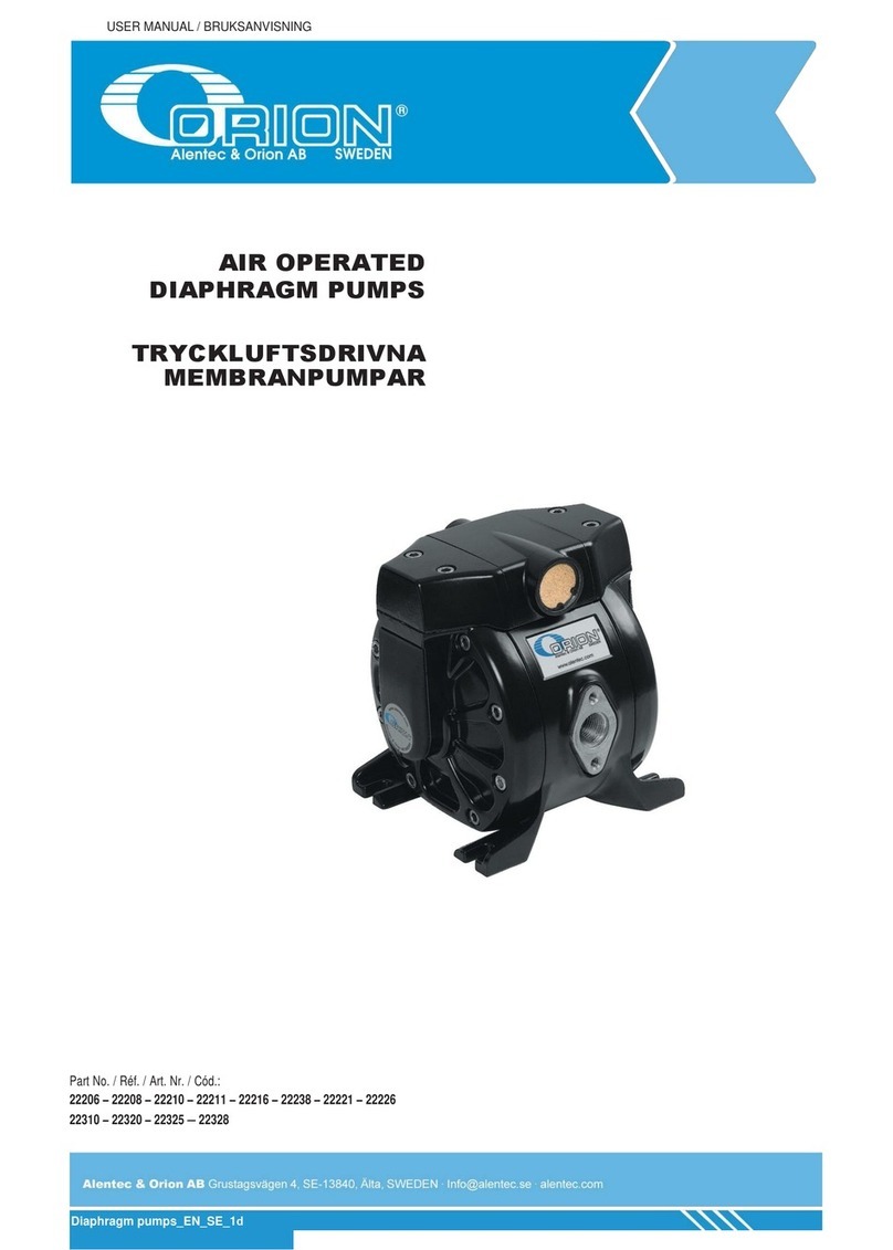
  9. Orion 22330 User manual

Orion 22330 User manual

1
Alentec & Orion AB Grustagsvägen 4, SE-13840, Älta, SWEDEN · [email protected] · www.alentec.com
USER MANUAL / BRUKSANVISNING
Part No. / Art. Nr. / Réf.:
22330
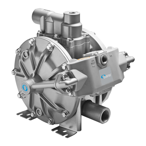
AIR OPERATED
DIAPHRAGM PUMP
TRYCKLUFTSDRIVEN
MEMBRANPUMP
105075B
Alentec & Orion AB Grustagsvägen 4, SE-13840, Älta, SWEDEN · [email protected] · www.alentec.com
2
TECHNICAL DATA / TEKNISKA DATA
22330
TECHNICAL DATA 22330
Ratio 1:1
Maximum free ow 250 l/mim (66,04 Us gal/min)
Delivery per stroke 0.62 l (21.82 oz)
Air pressure operating range 1,5 a 7 bar (22 to 102 psi)
Solid in suspension max size 5-6 mm (0.2-0.24 in)
Maximum suction head 5m (16.5 ft) dry, 8m (26.2 ft) wet
Weight 20 kg (44.09 lb)
Fluid inlet (single inlet) 1-1/2" BSP (F) + DIN2576 DN40 or NPT
(F) + ANSI B16.5 150 lbs
Fluid outlet 1-1/2" BSP (F) + DIN2576 DN40 or NPT (F
+ ANSI B16.5 150 lbs
Air inlet 1/2" NPSM (F)
Wetted part materials Aluminium, Acetal, Hytrel®, Stainless steel,
NBR, Zink plated steel
Noise level 80 dB
Temperature range 10 - 90 ºC
TEKNISKA DATA 22330
Tryckförhållande 1:1
Kapacitet (fritt öde) 250 l/mim
Leverans per slag 0.62 l
Lufttryck 1,5 a 7 bar
Max storlek på partiklar 5-6 mm
Maximal sughöjd 5m torr, 8m avluftad
Vikt 20 kg
Vätskeinlopp 1-1/2" BSP (F) + DIN2576 DN40 or NPT
(F) + ANSI B16.5 150 lbs
Vätskeutlopp 1-1/2" BSP (F) + DIN2576 DN40 or NPT (F
+ ANSI B16.5 150 lbs
Luftanslutning 1/2" NPSM (F)
Våta material Aluminium, Acetal, Hytrel®, Syrafast stål,
NBR, Förzinkat stål
Ljudnivå 80 dB
Temperaturspann 10 - 90 ºC
EN
SE
AIR CONSMPTION / LUFTFÖRBRUKNING / LUFTVERBRAUCH
FLOW / FLÖDE / DURCHFLUSS
OUTLET PRESSURE / VÄTSKETRYCK / AUSGANSDRUCK
1400
1200
1000
800
600
400
200
0
7
6
5
4
3
2
1
0
0 13.2 26.4 39.6 52.8 66.1
0 50 100 150 200 250
49.42
42.36
35.3
28.24
21.18
14.12
7.06
0
Nl/min.
SCFM
U.S. gpm
l/min
101.5
87
72.5
58
43.5
29
14.5
0
bar
psi
44 psi / 3 bar
73 psi / 5 bar
87 psi / 6 bar
102 psi / 7 bar
58 psi / 4 bar
102 psi / 7 bar
87 psi / 6 bar
73 psi / 5 bar
58 psi / 4 bar
44 psi / 3 bar
390
327
220
280
13
172
J
264
353
310
1/2” NPSM
AIR
EXHAUST
1-1/2” BSP
1-1/2” BSP
390
327
220
280
13
172
J
264
353
310
1/2” NPSM
AIR
EXHAUST
1-1/2” BSP1-1/2” BSP
Alentec & Orion AB Grustagsvägen 4, SE-13840, Älta, SWEDEN · [email protected] · www.alentec.com
3
GENERAL / ALLMÄNT / GÉNÉRALITÉSGENERAL / ALLMÄNT
Air operated double diaphragm pumps are air-powered, reciprocating
positive displacement pumps with two pumping chambers. Two diaphragms,
centrally located in the chambers, separate the compressed air (dry side)
from the uid being pumped (wet side). A shaft transmits the reciprocating
motion of one diaphragm to the other. A directional valve alternatively
distributes the air from one chamber to the other; thus a reciprocating
movement of the diaphragms is created. With each stroke, uid is
discharged by one of the diaphragms whilst the opposite diaphragm sucks
new uid into the expanding chamber. Check valves, two on the discharge
side and two on the suction side, control and direct the uid ow.
SAFETY INSTRUCTIONS
Use only original replacement components from Alentec & Orion AB.
Fluids not suitable for the pump can cause damage to the pump unit and
involve risk of serious personal injury.
Install and use the pump according to all local and national regulations and
abide all health and safety laws or legislation.
The pump can produce uid pressures equal to the air supply pressure. Do
not exceed the maximum allowable pressure of 100 psi (7 bar) air supply. The
total hydraulic pressure (differential pressure + system) should never exceed
100 psi (7 bar).
Never use a pump that leaks, that is damaged, that is corroded or otherwise it
may lack the capacity to contain the uid.
Frequently check that the bolts on the diaphragm cover of the pump are
torqued correctly.
Do not use a model with aluminium wetted surfaces to pump uids for human
consumption, there is a possibility of trace contamination of lead.
Danger of explosion if used 1,1,1-trichloroethane, methylene chloride or other
halogenated hydrocarbon solvents with aluminium wetted materials. It could
cause serious injury and property damage.
Inside the pump, diaphragms separate the uid that is being pumped from the
air supply. If a diaphragm breaks, the uid can leak out of the air exhaust and
contaminate the environment.
When handling hazardous uids, always route the air exhaust into a suitable
container and locate it in a safe place.
When the uid source level is situated higher than the pump, (ooded suction),
the outlet tank must be at a higher level than the product to prevent spills.
For pumps handling hazardous uids that are a danger to humans or to the
environment, install a suitable container surrounding the pump to prevent any
leaks or spills.
Ensure that the operators of this equipment are trained on the operation
and limitations. Use safety equipment as safety goggles or other equipment
required.
Tryckluftsdrivna dubbelmembranpumpar är luftdrivna, fram- och återgående
förträngningspumpar med två pumpkammare. Två membran, centralt
belägna i pumpen, separerar tryckluft (torr sida) från den vätska som
pumpas (våta sidan). En axel överför den fram- och återgående rörelsen
från ett membran till det andra. En ventilmekanism fördelar luften alternativt
från en kammare till den andra; så att en fram- och återgående rörelse
skapas av membranen. För varje slag, är trycks vätskan ut genom en av
membranen medan den motsatta membranet suger ny vätska in i den
expanderande kammaren. Backventiler, två på utloppssidan och två på
sugsidan, kontrollerar och styr vätskeödet.
SÄKERHETSANVISNINGAR
Använd endast reservdelar från Alentec & Orion AB.
Vätskor som inte är lämpliga för pumpen kan orsaka skador på pumpen och
innebära risk för allvarliga personskador.
Installera och använd pumpen enligt alla lokala och nationella bestämmelser
och följ alla lagar och regler för hälsa och säkerhet.
Pumpen kan producera vätsketryck lika med lufttrycket. Överskrid
inte högsta tillåtna tryck av 100 psi (7 bar) luft. Den totala hydraultryck
(differenstryck + systemet) ska aldrig överstiga 100 psi (7 bar).
Använd aldrig en pump som läcker, som är skadad, som korroderad eller på
annat sätt kan det saknar kapacitet att innehålla vätskan.
Kontrollera regelbundet att skruvarna på membranlocket på pumpen har
dragits åt korrekt.
Använd inte en modell med aluminium för att pumpa livsmedel, det nns en
risk att materialet innehåller spårämnen av bly.
Risk för explosion om 1,1,1-trikloretan, metylenklorid eller andra
halogenerade kolväten används med pumpkropp i aluminium. Det kan
orsaka allvarliga personskador och materiella skador.
Inuti pumpen separerar ett membran vätskan som pumpas från lufttillförseln.
Om ett membran går sönder, kan vätskan läcka ut ur luftutloppet och
förorena miljön.
Vid hantering av farliga vätskor, led alltid luftutblåset till en lämplig behållare
och placera den på ett säkert ställe.
När vätskan ligger högre än pumpen (dränkt pump), måste utloppstanken
vara högre än sugtanken för att förhindra spill.
För pumpar som hanterar farliga vätskor som är en fara för människor eller
miljön, installera pumpen i en lämplig behållare som omger pumpen för att
förhindra läckage eller spill.
Se till att alla som använder av denna utrustning är utbildade på
utrustningens driftinstruktioner och begränsningar. Använd skyddsutrustning
såsom skyddsglasögon eller annan utrustning som krävs.
ALLMÄNT
GENERAL EN SE
Alentec & Orion AB Grustagsvägen 4, SE-13840, Älta, SWEDEN · [email protected] · www.alentec.com
4
INSTALLATION / INSTALLATION
• Remove the pump from its package and install it on the chosen
location.
• Try to minimize the suction head. Install the pump as close as possible
to the uid being pumped.
• Remember to have enough space around the pump to perform
maintenance tasks.
• Keep in mind to connect the inlet and outlet of the pump correctly.
• In case of diaphragm pump failure, the air exhaust will expel the
product being pumped.
• When the pump is installed in a place where a spill of uid can cause
an environmental impact, the exhaust should be directed to a place
where this spill could be contained.
• Fasten all bolts with the torques contained in this manual.
The diaphragm pump can be installed in three general ways.
Flooded: The pumping system was designed with positive pressure at
the inlet. This is the best possible installation when you need to evacuate
the liquid from the drum or tank, or when working with viscous uids. Not
recommended for hazardous uids.
Self-priming: Pump is designed to generate vacuum. It is possible to
evacuate all the air from a hose or pipe without damaging the pump.
Maximum suction height is 19.69 ft (6 m), with the suction hose empty and
up to 26.25 ft (8 m) with the hose primed.
Submerged: All pumps can be immersed in uids. It is important to
verify that all components that are in contact with the uid are chemically
compatible. In this case, air exhaust and uid must be carried by hoses
(optional air connection).
• Ta pumpen ur förpackningen och installera det på den valda platsen.
• Försök att minimera sughöjden. Installera pumpen så nära som möjligt
till den vätska som pumpas.
• Tänk på att ha tillräckligt med utrymme runt pumpen för att utföra
underhåll.
• Kom ihåg att ansluta inloppet och utloppet hos pumpen på rätt sätt.
• I händelse av att ett membran går sönder, kommer luftutblåset att
trycka ut vätskan som pumpas.
• När pumpen installeras på en plats där ett utsläpp av vätska kan
orsaka miljöpåverkan, bör luftutblåset avledas till en säker behållare.
• Fäst alla skruvar med korrekt åtdragningsmoment som speciceras i
den här manualen.
Membranpumpen kan installeras på tre sätt.
Dränkt: Pumpsystemet utformas med positivt tryck vid inloppet. Detta är
den bästa möjliga installation när du behöver tömma vätska från fatet eller
tanken, eller när du arbetar med viskösa vätskor. Rekommenderas inte för
farliga vätskor.
Självsugande: Pumpen är konstruerad för att generera vakuum. Det är
möjligt att evakuera all luft från en slang eller ett rör utan att skada pumpen.
Maximal sughöjd är 6 m, med tom sugslang och upp till 8 m med fylld slang.
Nedsänkt: Alla pumpar kan sänkas ned i vätska. Det är viktigt att kontrollera
att alla komponenter som är i kontakt med vätskan är kemiskt kompatibla. I
detta fall måste luftutblås ledas ut med slang (extra luftanslutning).
RECOMMENDATIONS REKOMMENDATIONER
EN SE
Flooded / Dränkt / Geutet
Air /
Luft /
Zuluft
Air /
Luft /
Zuluft
Air /
Luft /
Zuluft
Exhaust /
Utblås /
Abluft
Submerged / Nedsänkt / GetauchtSelf priming / Självsugande / Selbstansaugend
Alentec & Orion AB Grustagsvägen 4, SE-13840, Älta, SWEDEN · [email protected] · www.alentec.com
5
GENERAL / ALLMÄNT / GÉNÉRALITÉSINSTALLATION / INSTALLATION
REPAIR AND MAINTENANCE / REPARATION OCH UNDERHÅLL
When installing the pump, be sure to perform grounding in the specied
location.
Also connect ground wires for the auxiliary equipment and piping.
Use a grounding cable of at least 12 gauge (2.0 mm2).
If the pump you have purchased is valid for Atex, a specic Atex manual will
accompany this one. Read this manual before operating the pump.
If the unit is marked with the symbol, it can be used in potentially
explosive atmospheres. Below this symbol, in the nameplate of the
pump, are indicated the areas for which the equipment is approved.
You will also nd the maximum allowable surface temperature in the same
plate.
Connect grounding wires to the pump, piping and all other equipment too.
When the pump operates ungrounded or with an incorrect connection,
friction between parts and abrasion caused by some uids that ow inside
the pump, can generate static electricity. Moreover, according to the type of
uid pump and the installation environment (such as gases in the air or the
type of the surrounding facilities) static electricity can cause re or electric
shock.
For proper operation of the pump and to prevent accidents which may
damage equipment and in the worst case, people, you must periodically
review the torques of the diaphragms covers and the directional valve. In the
next table are shown the appropriate torques for this purpose:
Vid installation av pumpen, se till att jorda pumpen på den anvisade platsen.
Anslut även jordkablar till extrautrustning och rörledningar.
Använd en jordkabel med minsta area 2,0 mm2.
Om pumpen du har är Atex-godkänd kommer en särskild Atex manual att
medfölja. Läs bruksanvisningen innan du använder pumpen.
Om enheten är märkt med symbolen, kan den användas i potentiellt
explosiva miljöer. Under denna symbol, på pumpens typskylt anges de
områden där utrustningen är godkänd. Du hittar också den högsta
tillåtna yttemperaturen på samma typskylt.
Kom ihåg att jorda all utrustning såsom pump, utrustning och rörledning.
När pumpen används ojordad eller med en felaktig anslutning, kan statisk
eletricitet skapas av friktion mellan delar samt nötning skapat av vissa
vätskor. Dessutom, baserat på val av pump och installationsmiljön (t.ex gas
i omgivande luft) kan statisk elektricitet skapa bränder eller ge stötar.
För att säkerställa att pumpen ska fungera korrekt och för att förebygga
olyckor som kan skada utrustning eller i värsta fall människor, måste
man med regelbundna intervaller kontrollera och eventuellt efterdra vissa
skruvar i pumpen. I följande tabell visas vilken del som avses och lämligt
åtdragningsmoment.
GROUNDING THE PUMP JORDNING AV PUMPEN
EN
TORQUES EN
SE
ÅTDRAGNINGSMOMENT SE
PART 22330
Diaphragm cover 20-30 Nm
Directional valve 15 Nm
Valve cap 8 Nm
DEL 22330
Lock till membran 20-30 Nm
Ventilmekanism 15 Nm
Lock till backventil 8 Nm
EN
SE
Alentec & Orion AB Grustagsvägen 4, SE-13840, Älta, SWEDEN · [email protected] · www.alentec.com
6
REPAIR AND MAINTENANCE / REPARATION OCH UNDERHÅLL
Before any intervention: DISCONNECT AIR SUPPLY OF THE PUMP. IT IS
NOT NECESSARY TO REMOVE THE PUMP FROM THE FLUID LINE.
1. Close uid valves.
2. Remove the directional valve while being careful not to damage the
seals shown in the gure.
3. Remove the diaphragm cap screws. Anticipate a drainage of uid from
inside the pump.
4. Remove the cover by gently pulling back.
5. Remove the used diaphragm and place the new one in the proper
position.
6. Assemble components. NOTE: To tighten these screws you must use
a torque wrench calibrated to (see torque table in this page).
When reassembling the diaphragm lid with its nuts, please follow the torque
sequence as shown in the picture. It is crucial to not use the required torque
values until the diaphragm lid is fully approximated to the central body using
the screws.
Innan reparationen påbörjas, STÄNG AV LUFTTILLFÖRSELN TILL
PUMPEN. DET ÄR EJ NÖDVÄNDIGT ATT MONTERA BORT PUMPEN
FRÅN RÖRSYSTEMET.
1. Stäng alla vätskeventiler.
2. Demontera ventilmekanismen, var noga med att inte tappa bort eller
skada tätningarna enligt bilden.
3. Demontera skruvarna till membranlocken. Var beredd med
uppsamlingskärl och dylikt då vätskan i pumpen kommer att rinna ut.
4. Demontera locket, dra det försiktigt utåt. Var beredd med
uppsamlingskärl och dylikt då vätskan i pumpen kommer att rinna ut.
5. Ta bort det trasiga membranenet och återmontera det nya i locket.
6. Montera pumpen i omvänd ordning. OBS! För återmontering, använd
korrekt åtdragningsmoment enligt tabellen ovan.
Vid återmontering av locket, dra åt skruvarna i ordningen som visas i
skissen nedan. Obs, dra åt samtliga skruvar löst först, så att locket ligger
jämt mot pumphuset innan det korrekta åtdragningsmomentet appliceras.
DIAPHRAGM REPLACEMENT BYTE AV MEMBRAN
EN SE
1
3
5
7
9
2
4
6
8
10
1
2
3
4
5
Alentec & Orion AB Grustagsvägen 4, SE-13840, Älta, SWEDEN · [email protected] · www.alentec.com
7
REPAIR AND MAINTENANCE / REPARATION OCH UNDERHÅLL
Remove the side cover on the right of the uid inlet as shown in the gure,
following the procedure to “Replace diaphragms”.
Once the shaft is visible, use the following procedures:
1. Remove the shaft from its housing by pulling it from one end. The
Teon® sleeve is threaded into the body. To remove use snap ring
pliers in the two holes indicated in the gure.
2. Once the cap has been removed, remove the quad ring inside the
pump body.
3. Replace the kit following the correct order shown in the assembly
drawing.
4. Reassemble the pump in reverse order.
Demontera locket till höger om vätskeinloppet enligt bilden, följ instruktioner
i ”byte av membran”.
1. När axeln är synlig, följ dessa instruktioner:
2. Ta bort axeln genom att dra ut den. Teon®-bussningen är gängad i
pumphuset. Använd en låsringstång i de två hålen enligt skissen för att
ta bort bussningen.
3. När bussningen är demonterat, ta bort quad-ring-tätningen i
pumphuset.
4. Ersätt delar i ordningen enligt skissen.
5. Återmontera pumpen i omvänd ordning.
PUSHING ROD AXEL
EN SE
Vid återmontering av locket, dra åt skruvarna i ordningen som visas i
skissen nedan. Obs, dra åt samtliga skruvar löst först, så att locket ligger
jämt mot pumphuset innan det korrekta åtdragningsmomentet appliceras.
When reassembling the diaphragm lid with its nuts, please follow the torque
sequence as shown in the picture. It is crucial to not use the required torque
values until the diaphragm lid is fully approximated to the central body using
the screws.
1
3
5
7
9
2
4
6
8
10
Alentec & Orion AB Grustagsvägen 4, SE-13840, Älta, SWEDEN · [email protected] · www.alentec.com
8
REPAIR AND MAINTENANCE / REPARATION OCH UNDERHÅLL
CHECK VALVES EN
AIR SENSOR EN
BACKVENTILER SE
LUFTSENSOR SE
1. Close uid valves.
2. Loosen the screws to remove
the directional valve. Take
special care with the seals.
3. Remove the valve cover by
loosening the screws with an
Allen wrench. Take note of the
orientation of the cap, as it is
critical to replace it correctly
during reassembly. Anticipate a
drainage of uid from inside the
pump.
4. Install a new set of valves
according to these assembly
drawings. Ensure that the
ball guides are assembled,
and tighten the screws with a
maximum torque (see torque
table).
5. Assemble the directional valve
with being careful not to damage
the O-rings and tighten the
screws with a maximum torque
of 132 lbf·in (15 N·m).
1. Remove the side cover.
2. Remove the four screws that secure the air sensor cover.
3. Remove all components of the sensor. Clean the area.
4. Introduce new components in the order shown.
5. Fit the side cover and tighten the screws.
1. Ta bort skyddslocket.
2. Skruva bort de fyra skruvarna till luftsensors lock.
3. Ta bort alla delarna i sensors. Rengör invändigt.
4. Montera de nya delarna i samma ordning.
5. Sätt på locken och dra åt skruvarna.
1. Stäng alla vätskeventiler.
2. Demontera ventilmekanismen,
var noga med att inte tappa bort
eller skada tätningarna.
3. Demontera locken till
backventilen(-erna) genom att
lossa på insexskruvarna. Märk
väl åt vilket håll locket sitter åt
då det är viktigt att det sitter åt
rätt håll vid återmontering. Var
beredd med uppsamlingskärl
och dylikt då vätskan i pumpen
kommer att rinna ut.
4. Montera nya backventiler
enligt skissen. Glöm ej
styrningspinnarna, montera
locket och dra åt med korrekt
åtdragningsmoment (se tabell).
5. Återmontera ventilmekanismen,
iaktag försiktighet med
tätningarna så de inte skadas.
Dra åt med 15Nm.
Alentec & Orion AB Grustagsvägen 4, SE-13840, Älta, SWEDEN · [email protected] · www.alentec.com
9
SPARE PART KITS / RESERVDELSSATSER
1
2
3
4
56
7
13
12
11
10
9
8
14
15
16
32
36
33
34
35
15
14
47
48
17
18
19
20
21
22
37 40
39
38
41
42
43
44
45
46
23 24 25 26 27 28 29
30 31
EN SE
FOR PUMP
22330 CONSIST OF BESTÅR AV POS. QUANTITY
/ ANTAL
242 66 10 Directional valve Ventilmekanism 1-13 1
242 66 11 Air sensor kit Luftsensor 23-31 1
242 66 12 Check valve Backventil 19 4
242 66 13 Check valve holder kit Backventilhållare 16-22 1
242 66 14 Diaphragm kit Membran 38, 41 2
242 66 15 Shaft seal kit Axeltätning 32-36 1
Alentec & Orion AB Grustagsvägen 4, SE-13840, Älta, SWEDEN · [email protected] · www.alentec.com
10
TROUBLESHOOTING / FELSÖKNING
SYMPTOM RECOMMENDED MEASURE
THE PUMP DOES NOT WORK
The discharge valve on the discharge side is not open. Open the discharge valve on the discharge side.
No air supply. Turn on the compressor and open the air valve and air regulator.
The air supply pressure is low. Check the compressor and the conguration of the air line.
Air leaks in connecting elements. Check the connection elements and the tightening of the screws.
The air pipes or ancillary equipment is clogged with mud. Check and clean the air line.
The exhaust port (mufer) of the pump is clogged with mud. Check and clean the exhaust port and mufer.
The uid pipe is clogged with mud. Check and clean the uid line.
Pump is clogged with mud. Remove, inspect and clean the pump body.
THE PUMP RUNS BUT NO FLUID COMES OUT
The valve on the suction side is not open. Open the valve on the suction side.
Too much suction or discharge height. Conrm the conguration of the pipe and reduce the height of the same.
Fluid pipe discharge side (including the lter) is clogged with mud. Check and clean the uid line.
Pump is clogged with mud. Dismantle the pump, check and clean.
The ball and ball seat is worn or damaged. Inspect and replace parts.
THE FLOW IS DECREASING
The air supply pressure is low. Check the compressor and the conguration of the air line.
The air line or peripheral equipment clogged with mud. Check and clean the air line.
Valve discharge side drive will not open normally. Adjust the discharge valve discharge side.
The air mixes with the uid. Replenish uid and check the conguration of the pipe on the suction side.
Cavitation occurs. Adjust air supply pressure and discharge pressure and reduce the suction.
Vibrations. Adjust air supply pressure and discharge pressure. Reduce the ow of the inlet
valve to adjust pressure and volume of uid.
Ice formation in the air exhaust. Remove ice from the air bypass valve and check and clean the air lter. Use a pipe
in the exhaust air that the ice does not form in the mufer.
The uid line (including the lter) plugged with mud. Check and clean the uid pipe and strainer.
The exhaust port (mufer) of the pump is clogged with mud. Check and clean the exhaust port and mufer.
Pump is clogged with mud. Remove, inspect and clean the pump body.
LEAKAGE OF FLUID THROUGH THE HOLLOW EXHAUST (SILENCER)
The diaphragm is damaged. Remove and inspect the pump and replace the diaphragm.
IRREGULAR NOISE
The air supply pressure is too high. Adjust air supply pressure.
The pump is clogged with sludge particles larger than the diameter allowed. Remove, check and clean the pump body.
IRREGULAR VIBRATION
The elements of connection and the support of the pump are loose. Review each element of connection and tighten the screws.
The air supply pressure is too high. Adjust air supply pressure.
The check valve vibrates. Adjust air supply pressure and exhaust pressure.
IN FLUID WITH AIR BUBBLES
Diaphragm damaged. Replace diaphragm.
Suction hose loose or broken. Tighten or replace.
AIR LEAK PRESSURE OF 3 TO 7 BAR
Wear directional valve. Replace directional valve components.
NO START-UP AND IS LEAKING AIR WITHOUT CYCLES
Stiff air sensors. Change air sensor.
Wear directional valve. Replace.
EN
Alentec & Orion AB Grustagsvägen 4, SE-13840, Älta, SWEDEN · [email protected] · www.alentec.com
11
TROUBLESHOOTING / FELSÖKNING
SYMPTOM REKOMMENDERAD ÅTGÄRD
PUMPEN FUNGERAR EJ
Utloppsventil är stängd. Öppna ventilen på utloppssidan.
Ingen luftanslutning. Starta kompressorn och öppna luftventiler och lterregulator.
Lufttrycket är lågt. Kontrollera kompressor och luftledning.
Luftläckage i luftledning. Kontrollera luftledningens anslutningar och skarvar.
Luftledning eller luftbehandlingsenheter är igensatta. Kontrollera och rengör luftledningen.
Luftutblåset på pumpen är igensatt. Kontrollera och rengör luftutblås och ljuddämpare.
Utloppsledning är igensatt. Kontrollera och rengör utloppsledning.
Pump är igensatt. Demontera, kontrollera och rengör pump- samt pumpkropp.
PUMPEN GÅR MEN INGEN VÄTSKA KOMMER
Ventilen på sugsidan är stängd. Öppna ventilen på sugsidan.
För hög sug- eller tryckledning. Kontrollera maximala höjder, se rekommendationer i denna manual. Justera ledningar.
Utloppsledning inklusive lter är igensatt. Kontrollera och rengör utloppsledning.
Pump är igensatt. Demontera, kontrollera och rengör pump- samt pumpkropp.
Kulan (kulorna) och/eller kulsäte är utslitet eller skadat. Kontrollera och byt ut delar.
FLÖDET MINSKAR
Lågt lufttryck. Kontrollera kompressor och lterregulator.
Luftledning och tillbehör är igensatta. Kontrollera och rengör luftledning.
Ventil på utloppssidan öppnar ej normalt. Justera utloppsventil.
Vätskan är blandad med luft Fyll på vätska och kontrollera sugledning.
Kavitation uppstår. Justera lufttryck, mottryck, reducera sugledningens längd.
Vibrationer. Justera lufttryck, mottryck. Reducera ödet på inloppsventil för att justera tryck och
utgående öde.
Isbildning i ljuddämpare. Ta bort is från by-pass ventilen och kontrollera och rengör luftlter. Led bort
utloppsluften så att isbildning inte sker i ljuddämparen.
Utloppsledning inklusive lter är igensatt. Kontrollera och rengör utloppsledning.
Luftutblåset på pumpen är igensatt. Kontrollera och rengör luftutblås och ljuddämpare.
Pump är igensatt. Demontera, kontrollera och rengör pump- samt pumpkropp.
VÄTSKELÄCKAGE GENOM LJUDDÄMPARE
Membranet är skadat. Demontera och undersök pump och byt ut membran.
OREGELBUNDNA LJUD
Lufttrycket är för högt. Justera lufttryck.
Pumpen är igensatt med större fasta partiklar än vad pumpen klarar av. Demontera, kontrollera och rengör pump- samt pumpkropp.
OREGELBUNDNA VIBRATIONER
Anslutningsslangar eller pumpfäste är lösa. Kontrollera alla anslutande delar och dra åt skruvar till pumpfäste.
Lufttrycket är för högt. Justera lufttryck.
Vibrationer i backventiler. Justera lufttryck.
VÄTSKAN BLANDAS MED LUFT
Membranet är skadat. Demontera och undersök pump och byt ut membran.
Sugslang ej tät eller trasig. Dra åt eller byt ut.
TRYCKLUFTSLÄCKAGE MELLAN 3 – 7 BAR
Utsliten ventilmekanism. Byt ut ventilmekanism.
PUMPEN STARTAR EJ OCH LÄCKER LUFT UTAN ATT VÄXLA
Fastsatta luftsensorer. Byt ut luftsensor.
Byt ut ventilmekanism. Byt ut.
SE
Alentec & Orion AB Grustagsvägen 4, SE-13840, Älta, SWEDEN · [email protected] · www.alentec.com
12
EC CONFORMITY DECLARATION / KONFORMITETSDEKLARATION
Alentec&Orion AB, Grustagsvägen 4, SE-13840, Älta, Sweden, declares by the present certicate that the mentioned machinery is
in conformity with the following standards or other normative documents (TÜV S9211282), (DIN 24558 / 10.91),
(DIN EN 292 / 2/11.91) and has been declared in conformity with the EC Directive (2006/42/EEC).
Alentec&Orion AB, Grustagsvägen 4, SE-13840, Älta, Sverige, deklarerar genom detta certikat att de omnämnda utrustningarna
är i överensstämmelse med följande standarder eller normerande dokument (TÜV S9211282), (DIN 24558 / 10.91), (DIN EN 292 /
2/11.91) och har blivit deklarerade i enlighet med EC Direktiv (2006/42/EEC).
EN
SE
105075B
Alentec & Orion AB Grustagsvägen 4, SE-13840, Älta, SWEDEN · [email protected] · www.alentec.com
Krister Tynhage
Managing Director
Olle Berglund
Product Manager

Other Orion Water Pump manuals

Orion 22760 User manual

Orion

Orion 22760 User manual

Orion DP200 Series Operating manual

Orion

Orion DP200 Series Operating manual

Orion KRF08A-B-04E User manual

Orion

Orion KRF08A-B-04E User manual

Orion 12540 User manual

Orion

Orion 12540 User manual

Orion 22750 User manual

Orion

Orion 22750 User manual

Orion 22772 User manual

Orion

Orion 22772 User manual

Orion 12750 User manual

Orion

Orion 12750 User manual

Orion KRF110-V-04E User manual

Orion

Orion KRF110-V-04E User manual

Orion 22206 User manual

Orion

Orion 22206 User manual

Orion 21205 User manual

Orion

Orion 21205 User manual

Orion 12626 User manual

Orion

Orion 12626 User manual

Orion 22771 User manual

Orion

Orion 22771 User manual

Orion 220VAC User manual

Orion

Orion 220VAC User manual

Orion 22705 User manual

Orion

Orion 22705 User manual

Orion 11116 User manual

Orion

Orion 11116 User manual

Orion 21650 User manual

Orion

Orion 21650 User manual

Orion 21200 User manual

Orion

Orion 21200 User manual

Orion 22206 User manual

Orion

Orion 22206 User manual

Orion 22802 User manual

Orion

Orion 22802 User manual

Popular Water Pump manuals by other brands

Buchi V-500 manual

Buchi

Buchi V-500 manual

Calpeda e-idos E-MXPM operating instructions

Calpeda

Calpeda e-idos E-MXPM operating instructions

Wilo Initial JET Installation and operating instructions

Wilo

Wilo Initial JET Installation and operating instructions

Calpeda NMS operating instructions

Calpeda

Calpeda NMS operating instructions

GORMAN-RUPP 02F1-GL Application, Installation, Operation, and Maintenance Manual

GORMAN-RUPP

GORMAN-RUPP 02F1-GL Application, Installation, Operation, and Maintenance Manual

Agilent Technologies VHS-4 instruction manual

Agilent Technologies

Agilent Technologies VHS-4 instruction manual

KNF FP 70 installation instructions

KNF

KNF FP 70 installation instructions

Kessel Aqualift F Mono Instructions for installation, operation and maintenance

Kessel

Kessel Aqualift F Mono Instructions for installation, operation and maintenance

RIDGID RWCS50T Operating instructions and parts manual

RIDGID

RIDGID RWCS50T Operating instructions and parts manual

GORMAN-RUPP PUMPS 12B65-B Installation, operation, and maintenance manual with parts list

GORMAN-RUPP PUMPS

GORMAN-RUPP PUMPS 12B65-B Installation, operation, and maintenance manual with parts list

REMS Calc-Push instruction manual

REMS

REMS Calc-Push instruction manual

SFA SANISUB S ZPK Series Operating & installation manual

SFA

SFA SANISUB S ZPK Series Operating & installation manual

Sage the Vac Q SBL002 quick guide

Sage

Sage the Vac Q SBL002 quick guide

PAPILLON NARWHAL instruction manual

PAPILLON

PAPILLON NARWHAL instruction manual

SKC Pocket Pump TOUCH operating instructions

SKC

SKC Pocket Pump TOUCH operating instructions

Sealey WPB050 instructions

Sealey

Sealey WPB050 instructions

Giant P426HHP Operating instructions/ repair and service manual

Giant

Giant P426HHP Operating instructions/ repair and service manual

Textron GREENLEE UTILITY H4670 instruction manual

Textron

Textron GREENLEE UTILITY H4670 instruction manual

manuals.online logo
manuals.online logoBrands
  • About & Mission
  • Contact us
  • Privacy Policy
  • Terms and Conditions

Copyright 2025 Manuals.Online. All Rights Reserved.