Bongshin BS-105 User manual

BS-105
Digital Indicator
The Better Way for Weighing &
Measurements

1
CONTENTS
Introductions . . . . . . . . . . 2
The Features of BS-105 . . 3
Technical Specification . . 4
Dimensions . . . . . . . . . . . . . 6
Front Panel . . . . . . . . . . . . 7
Rear Panel . . . . . . . . . . . . . . 9
Parameter . . . . . . . . . . . 14
ZERO Calibration . . . . . . . 19
Actual Load Calibration . . . 20
Equivalent Calibration . . . 22
Comparator Data . . . . . . . 24
Hold Function . . . . . . . . . 32
Key Lock . . . . . . . . . . . 34
Option . . . . . . . . . . . 35
Error Message
and Trouble Shooting . . . 43

2
Introduction
1. Introduction
Thank you for purchasing BS-105 High precision digital indicator.
Check for any breakdown during transit and discrepancy of the
specification. Always keep this manual at hand.
The BS-105 Series are configured as follows :
Check that there is no discrepancy between the model and its
specifications you have chosen when ordering and the model and its
specifications under your hand.
In order to obtain the highest performance of your BS-105, thoroughly
read this manual before use.
2. Precautions
■ Place the indicator on a flat and stable surface.
■ Applying voltage and current exceeding the maximum permissible
value results in the breakdown of the meter.
■ Do not severely press because the light pressing of keys can incite
the operation.
■ Do not subject the scale to sudden temperature changes.
Operating temperature : -10℃~+50℃
■ Keep the scale away from strong EMI noises may cause incorrect
weight readings.
■ Keep the main body from rain and keep in dry area.
■ Do not use inflammable materials in cleaning.
■ The contents of this manual are subject to change without notice
for further improvement.

3
The Features of BS-105
1. Features
■ 24 bit Sigma-Delta A/D converter for high accuracy.
■ Appropriate for weight and measurement system.
■ Simple full digital calibration.
■ Simulative (mV/V memory) or live load calibration.
■ Watchdog circuitry (system restoration)
■ Weight Back-up (power on actual weight)
2. Main Function
■ Various specification of weight conversion speed.
(Digital Filter Function)
■ 3 Set point relay output.
■ Hold, peak hold and auto zero.
■ Optional serial output or analog output.
■ User can set the max. weight which users want to and division
at one’s disposal.

4
Technical Specification
1. Analog Input & A/D Conversion
Analog signal input range 0mV ~ ±30mV
Non-linearity 0.01% F.S. max.
Max. Display resolution 99,999d
Min. Input sensitivity 0.3μV/Digit (min.)
Temperature drift Zero : ±0.1μV/℃ RTI max.
Span : 10ppm/℃ max.
Load cell excitation
Voltage
DC 5V ±5%, 60㎃
(350 ohm x 4 load cells)
Input Noise ±0.3μVp.p
Input Impedance 10㏁
A/D converter 24bit Sigma-Delta
A/D internal resolution Approx. 1,000,000
A/D sampling speed 50 times/sec
Display range -19,999 ~ 99,999
2. Digital Part
Display LED, 7 Segment 8.0mm high
5 Digits
Display speed 50 times/sec ~ 1 times/sec
Polarity indication (-) “-”Minus sign
Annunciators HOLD, ZERO, STABLE,
Relay point(LO, OK, HI)
Display increments
1, 2, 5, 10, 20, 50, 100, 200 selectable
Decimal Point Selectable to any points
5
3. Technical
Operating voltage DC 24V ( DC 20 ~ 27V)
Power consumption Approx. 10VA
Operating temperature
-10℃ ~ 50℃
Overall dimensions 48(W) x 48(H) x 138.5(D)
Weight Approx. 170 g
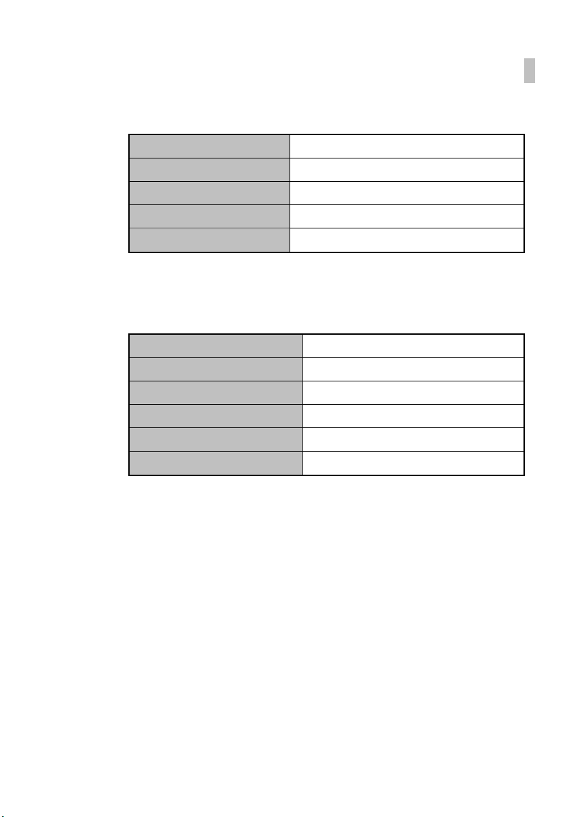
4. Option
Standard Relay 3CH Output
Option – 1 RS-232C (Serial output)
Option – 2 RS-422 (Serial output)
Option – 3 RS-485 (Serial output)
Option – 4 DC 0 ~ 10V (Analog output)
Option – 5 DC 4 ~ 20mA (Analog output)
Example) Option- 4 : Relay 3CH + DC 0 ~ 10V
6
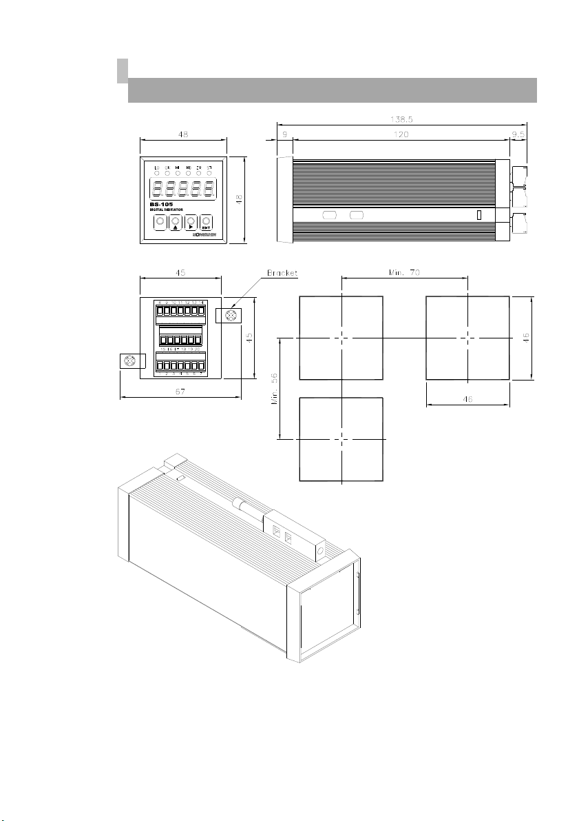
Dimensions
M
(unit : mm)
Panel cut-out
FRONT
REAR
To mount the BS-105 to the panel, remove its fittings and insert it through
the hole in the front of the panel. From the back of the panel, fix the
product to the panel with the fittings.

7
Front Panel
M
Key Switch
Weight Value Display
Status Lamp
1. Display Lamp ( )
LO (L1) lamp : It will lamp when 1step control works.
Indicates the result of judgment and turns on
if the measured value < LO judgment value.
OK (L2) lamp : It will lamp when 2step control works.
Indicates the result of judgment and turns on
if LO judgment value ≦ the measured value ≦
HI judgment value.
HI (L3) lamp : It will lamp when 3step control works.
Indicates the result of judgment and turns on
if the measured value > HI judgment value.
HD (Hold) lamp : Lamp is on when moving object is weighed.
Turns on if “peak hold/ instant hold” is on.
ZR (Zero) lamp : ON when the current weight is 0 kg.
Turns on if “digital zero” is on.
ST (Stable) lamp : ON when the weight is stable.
8
M1
2
3
4
M1
M1
4
4
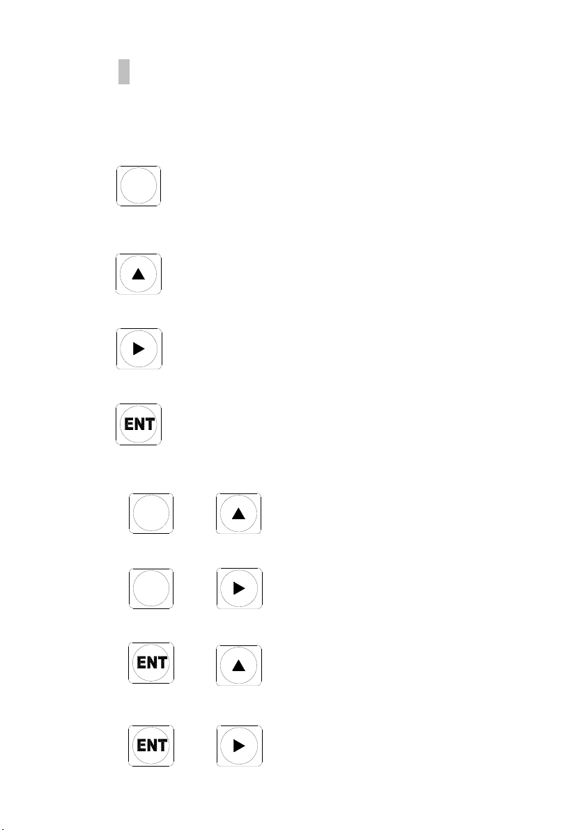
2. Keyboard
1) Pressing the increments and mode keys together changes
to the parameter setting mode.
2) Returns to the measurement mode.(ESC)
3) Selects the item to be set.
1) Holding down the increment key for about two second
moves to the peak hold & instant mode.
2) Changes the value or content of a selected digit.
(Increments the value)
1) Holding down the increment key for about one second
moves to the peak hold & instant clear mode.
2) Changes the digit to be set.
1) Store current condition and exit.
+ = Parameter setting mode
+ = Relay setting mode
+ = Digital zero function
+ = Key LOCK or Key LOCK clear mode
2
3
2
3
9
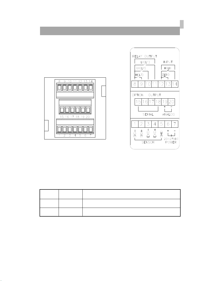
Rear Panel
■ POWER (DC IN) :
Use a stable power supply DC20~27V
Connect power supply to terminals No.6 and No.7.
Pin No. 명칭 내용
6 POWER Power terminal without polarity for both DC24V
7 POWER Power terminal without polarity for both DC0V
※ You can also connect regardless of the polarity.

10
■ LOAD CELL : Please connect the indicator connector with the wire of
load cell according to the color.
The wire color of load cell according to a manufactures.
Maker
1
SIG-
2
SIG+
3
EXC-
4
EXC+
5
SHIELD
BONGSHIN BLUE GREEN WHITE RED SHIELD
CAS, TMI, AND BLUE GREEN WHITE RED SHIELD
BLH RED WHITE BLACK GREEN YELLOW
INTERFACE WHITE GREEN BLACK RED SHIELD
KYOWA WHITE GREEN BLACK RED SHIELD
P.T. WHITE GREEN BLACK RED SHIELD
SHOWA BLACK WHITE BLUE RED SHIELD
SHINKOH WHITE GREEN BLACK RED SHIELD
TML GREEN WHITE BLACK RED SHIELD
TFAC BLACK WHITE BLUE RED YELLOW
HUNTLEIGH WHITE RED BLACK GREEN SHIELD
※ Because wire color may be different according to a manufacture and
load cell models. Please refer for the data sheet of load cell.
Cautions 1. When connecting a six-wire type strain gage sensor, short-
circuit (EXC+ and SEN+)(EXC- and SEN-), respectively.
Cautions 2. Applied voltages to the strain gage sensor are 10.
When any sensor rated below the applied voltage is connected,
it may generate heat or be damaged
Pin no. Signal name Contents
1 SIG- (Blue) Load cell output (-)
2 SIG+ (Green) Load cell output (+)
3 EXC- (White) Load cell Input Voltage (-)
4 EXC+ (Red) Load cell Input Voltage (+)
5 SHIELD Shield
11
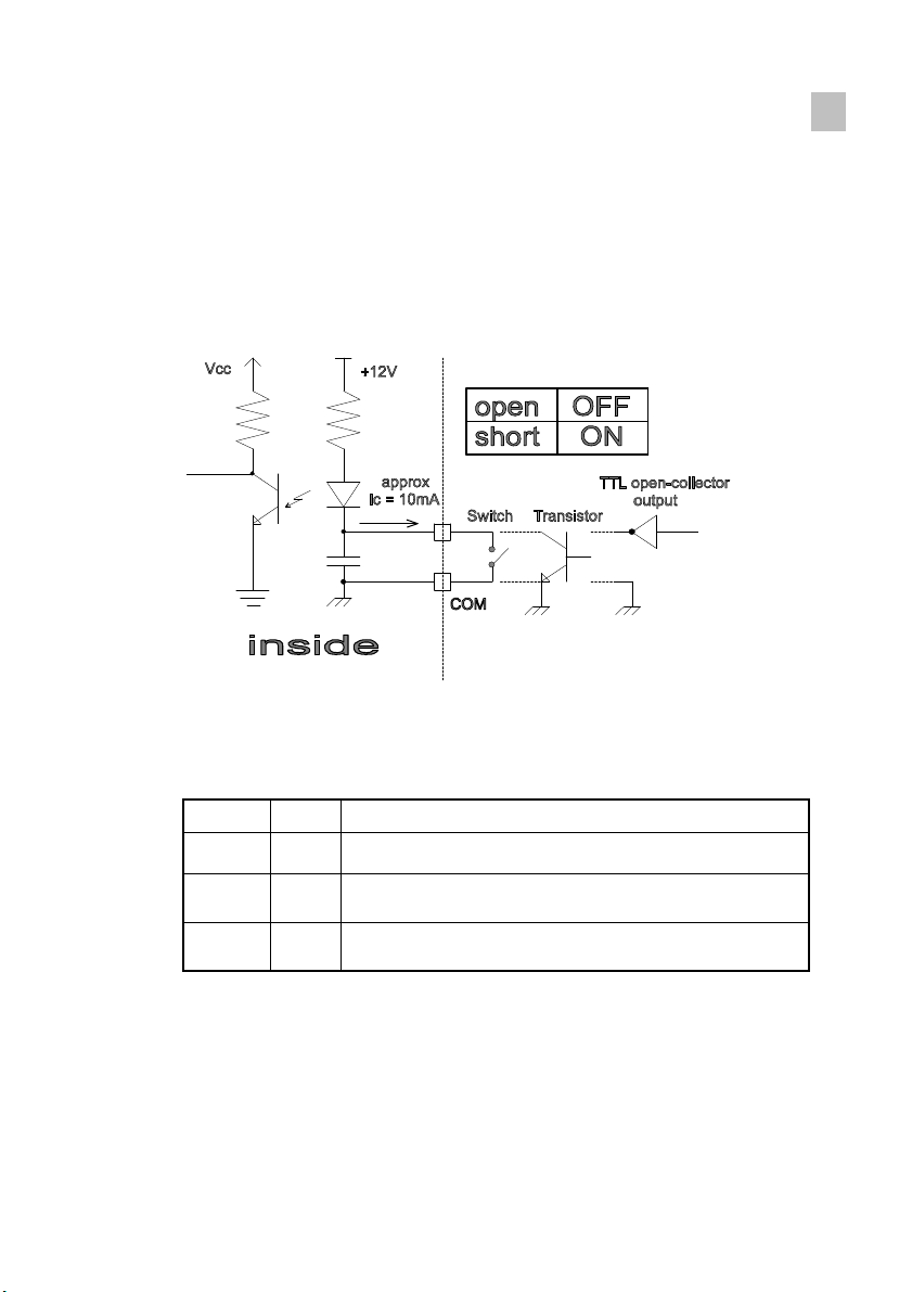
■ IN-PUT : COM, ZERO, HOLD
This key is to control a equipment from the outside .
Please connect between COM terminal and each input terminal .
Because the power of input terminal was connected with 12V voltage
From the inside.
* An electric current is about 10mA.
* Please make the minimum time to input a data with over 50msec.
Pin No. Name Description
12 COM Common for all external control terminals.
13 ZERO Control for digital zero function. Enabled when
short-circuited or at the same potential as COM.
14 HOLD Control for hold function. Enabled when short-
circuited or at the same potential as COM.
12
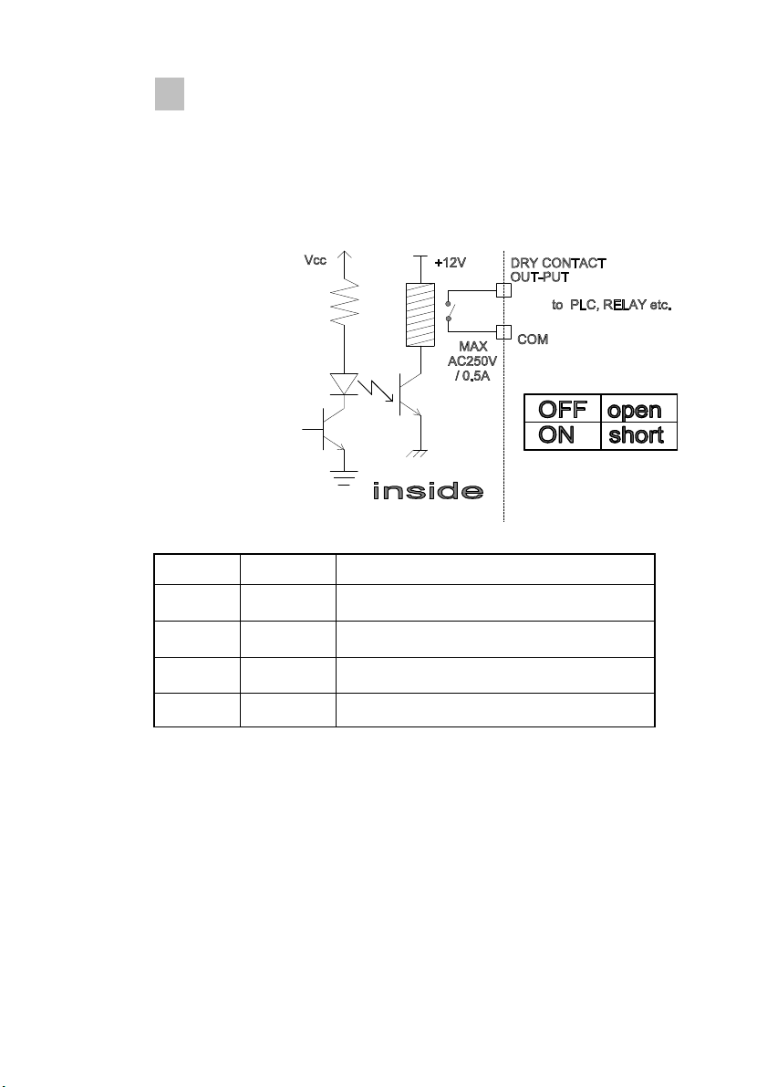
■ RELAY OUTPUT : COM, HI(L3), OK(L2), LO(L1)
Connect between COM terminal and OUTPUT terminal
With the earth of no electric power.
Please use the output data For a signal only, don’t use it for working.
Max earth capacity : AC250V / 0.5A
Pin No. Name Description
8 COM Common terminal for relay output
9 HI (L3) HI (L3) output terminal (a, b contact)
10 OK (L2) OK (L2) output terminal (a, b contact)
11 LO (L1) LO (L1) output terminal (a, b contact)

13
■ OPTION : Analog output (0~10V, 4~20mA) & Serial communication
(RS-232C, RS-422/485) option.
Analog output (0~10V, 4~20mA) option
Pin No. Name Description
19 V-OUT or A-OUT Voltage output terminal (0~10V or 4~20mA)
20 COM Common terminal for analog output.
Serial output (RS-232C) option
Pin No. Name Description
15 TX RS-232C transmission
16 RX RS-232C reception
17 SG Common terminal for communications
18 NC Do not connect this terminal
Serial output (RS-422) option
Pin No. Name Description
15 TXD (+) RS-422 TX(+)
16 TXD (-) RS-422 TX(-)
17 RXD (+) RS-422 RX(+)
18 RXD (-) RS-422 RX(-)
Serial output (RS-485) option
Pin No. Name Description
15 TXD (+) RS-485 TXD(+)
16 TXD (-) RS-485 TXD(-)
※ Both end side of a wire must be connected by the termination of 300Ω.
14
Information on Each Parameter
Indication Name Setup options Default
value
Calibration data
LC.CAL
Load cell
Rated output
set
1 mV/V ~3 mV/V 2.0000
SCALE Maximum
Capacity set 0~99999 10000
At.CAL S
p
an weight
set 0~99999 20000
Function data
biP Display Mode biP (+/- display)/ uniP (+ display) biP
dP.2 Decimal
Point set 0(0)/1(0.0)/2(0.00)/3(0.000)/4(0.0000) 2
ds.1 Minimum
Division set 1/ 2/ 5/ 10/ 20/ 50/ 100/ 200 digit 1
dU.2
Number of
average
operations
setup
1/ 2/ 5/ 10/ 25/ 50 2
Zt.oFF Zero
Tracking set OFF/ON OFF
AZ.oFF Auto zero
backup set OFF/ON OFF
Hd.oFF Hold function
set
OFF(No used)
/P(Peak Hold)/ I(Instant Hold) OFF
tare Manual Tare
weight set 0~99999 00000
Condition data (Serial interface option)
Id.0 E
q
ui
p
ment
ID setup 0 ~15 0
r.232 Communica-
tion select
r.232(RS-232C)/r.422(RS-422)/
r.485(RS-485) r.232
r.9600 Baud rate
setup
1200/2400/4800/9600/1920(19200)/
3840(38400) 9600
Par.no Parity bit Par.no(None)/Par.Ev(Even)/Par.Od(Odd) Par.Ev
Rc.on Communica-
tion mode ON(Data is required)/OFF(Stream mode) ON
15
Condition data (Analog output option)
dA.LO
Analog
output LO
indication
setup
0~99999 00000
dA.HI
Analog
output HI
indication
setup
0~99999 10000
Indication Name Setup options Default
value
Comparator data
rLY.1H
L1 HI side
judgment
value setup
-9999 ~ 99999 10000
rLY.1L
L1 LO side
judgment
value setup
-9999 ~ 99999 10000
r1H.on L1 Relay
motion mode r1H.on /r1L.on/ r1r.on r1H.on
rLY.2H
L2 HI side
judgment
value setup
-9999 ~ 99999 9999
rLY.2L
L2 LO side
judgment
value setup
-9999 ~ 99999 5001
r2H.on L2 Relay
motion mode r2H.on /r2L.on/ r2r.on r2H.on
rLY.3H
L3 HI side
judgment
value setup
-9999 ~ 99999 5000
rLY.3L
L3 LO side
judgment
value setup
-9999 ~ 99999 5000
r3H.on L3 Relay
motion mode r3H.on /r3L.on/ r3r.on r3H.on

16
1. Calibration data
1-1 Load cell rated output set (LC.CAL)
․ Set the rated output value(mV/V value) for the strain gauge sensor.
․ The setting rage of the rated output value for strain gauge sensor is 0.1 to
3.0 mV/V.
1-2 Maximum Capacity set (SCALE)
․ Set the indicated value when the rated output value is acquired and
finalized.
․ Setting range of SCALE set value (indicated value) 100 to 99999.
․ Acquire both load cell rated output set value and measured value (SCALE
value) and finalize with “ENTER” key.
1-3 Span weight set (At.CAL)
․ Actual load is performed by applying actual load to the connected strain
gauge sensor, and by setting the indicated value (SPAN set value) at the
time.
․ Setting range of SCALE set value (indicated value) 100 to 99999.
․ Resolution in this meter is 20000 at the time of a 2.0000 mV/V value.
2. Function data
2-1 Display mode (biP)
․ “biP” +/- display, “uniP” + display, “
2-2 Decimal point set (dP.2)
․ Set the decimal point position displayed on the set-value select screen.
․ Setting items : 0(0), 1(0.0), 2(0.00), 3(0.000), 4(0.0000)
2-3 Minimum Division set (ds.1)
․ Set the minimum updating width of indicated values.
․ Set it on the set-value select screen.
․ Setup items : 1, 2, 5, 10, 20, 50, 100, 200
2-4 Average operations setup (dU.2)
․ This function is provided for the moving average of data after A/D
conversion so as to reduce the fluctuation of the indicated values.
․ As the number of times of moving average is increased, the indicated
value is stabilized. However response becomes slow.

17
․ Set it on the set-value select screen.
․ Setup items : 1, ,2, 5, 10, 25, 50
2-5 Zero Tracking set (Zt.oFF)
․ This function is provided to correct automatically the slow change of the
zero point due to a change in the environment etc.
When the indicated value is below the ZT width, the indicated value is set
to “0” and internal correction is performed at every ZT cycle.
2-6 Auto ZERO backup set (AZ.oFF)
․ ON/OFF setting can be performed by pressing by pressing the
“increment” key one at a time.
․ When backup is set to OFF, Digital ZERO continues even when power is
turned OFF/ON.
2-7 HOLD Function set (Hd.oFF)
․ This function is provided to detect one sample with a peak, instant hold,
and point of inflection, holds the indicated value, performs HI/OK/LO limit
comparison simultaneously, and outputs the result.
․ Turning on Hold control terminal signal with both “HOLD” key turned on
will not be accepted. Priority is given to “HOLD” key.
․ Peak HOLD :
The peak hold function retains one of the maximum values and provides
output for that value. Selection from these values is made using the hold
function data.
․ Instant HOLD :
The Hold function temporarily retains the indication.
2-8 Manual TARE Weight set (tare)
․ The purpose of using tare is to subtract a certain weight on the real
weight.
․ When you already know the tare weight, press key tare and input tare
weight with arrow keys and memorize it by pressing “ENTER” key.
․ Setting range of TARE set value (indicated value) 99999.
3. Condition data (Serial Interface option)
3-1 Equipment ID setup (Id.0)
․ The ID is necessarily required to connect several indicators to control
together with a host PC.
․ Setting range : 0 to 15

18
3-2 Communication select (r.232)
․ Select RS-232C/RS-422/RS-485 communication.
․ Setup items : r.232(RS-232C)/r.422(RS-422)/r.485(RS-485)
3-3 Baud rate setup (r.9600)
․ To enable the communication mode, proper baud rate should be set
within r1200~r3840, in which r1920 means 19200bps and r3840 means
38400bps.
․ Setup items : 1200, 2400, 4800, 9600, 1920(19200), 3840(38400)
3-4 Parity bit setup (Par.Ev)
․ Communication parity bit set..
․ Setup items : Par.no(None)/Par.Ev(Even)/Par.Od(Odd)
3-5 Communication mode setup (Rc.on)
․ Rc on : Transmit when data is required
․ Rc oFF : Stream mode
․ Serial communication protocol.
4. Condition data (Analog output option)
4-1 Analog output LO indication setup (dA.LO)
․ Set an indicated value when analog output is 0V or 4mA.
․ Setting range : 0 to 99999
4-2 Analog output HI indication setup (dA.HI)
․ Set an indicated value when analog output is 10V or 20mA.
․ Setting range : 0 to 99999
19
2
4
ZERO Calibration
The digital zero function zeros the indication given at an arbitrary timing.
Thereafter, the function shows the amount of change from the point of
zeroing. However, this function serves as an indication resetting function for
a frequency measuring unit. Thus, the digital zero function can be used to
reset the indication when there is no input signal at all.
Note that, the on/off control of the digital zero function can be achieved by
means of terminal control or front panel keys. In the case of terminal control,
the digital zero function is turned on by short circuiting the ZERO and COM1
terminals or setting both terminals to the same voltage level. The indication
at that moment is zeroed. In the case of control with the front panel keys,
hold down the enter key and press the increment for about 1 second to zero
the indication at that moment.
1. Method of Setting zero
Pressing the key while pressing the key
and zero set mode.
※ Note : The setup condition are protect clear.
If these conditions are not satisfied, an error indication appears
and the display returns.
2. Digital ZERO Backup
Function data
AZ.oFF Auto zero
backup set OFF/ON OFF
ON/OFF setting can be performed by pressing by pressing the “increment”
key one at a time.
When backup is set to OFF, Digital ZERO continues even when power is
turned OFF/ON.
Table of contents
Other Bongshin Measuring Instrument manuals


Popular Measuring Instrument manuals by other brands

Svantek
Svantek SVAN 971 user manual

DayTronic
DayTronic 3770 instruction manual

Ralston Instruments
Ralston Instruments LC10 Series quick start guide

Nokeval
Nokeval 592D manual

PCB Piezotronics
PCB Piezotronics 3713E112G Installation and operating manual

Ludlum Measurements
Ludlum Measurements 4906AB checkout procedure


Endress+Hauser
Endress+Hauser Stamolys CA71SI-Ax0A3A1 technical information

T&D
T&D TR-81 instruction manual

Bosch
Bosch DLE 50 Professional operating instructions

Triplett
Triplett ET400 user manual

Franklin Fueling Systems
Franklin Fueling Systems EVO 200 Operation guide

Siargo
Siargo Thermal-D MF/FS4308 Series user manual