Bongshin BS-7300XL Quick start guide


1
7CBH9BHG
DF9:579""""""""""&
H97<B=75@ GD97=:=75H=CB " " )
8=A9BG=CBG"""""""""""""+
:FCBHD5B9@"""""""""""",
F95FD5B9@"""""""""""""" %%
=BGH5@@5H=CB"""""%)
75@=6F5H=CB AC89 5WhiU`
"%*
75@=6F5H=CB AC89 G]ai`Uh]cb
&-
G9H!IDAC89"""""""""""(%
CDH=CB"""""""""""""")$
9ffcfAYggU[Y
5bX HfciV`Y G\cch]b[ " " " **

2
DF9:579
%"=BHFC8I7H=CB
Thank you very much for your purchasing BONGSHIN Digital Weighing
Indicator of BS-7300XL.
This Instruction Manual will lead you to use BS-7300XL with top reliability,
High speed, high accuracy.
BS-7300XL is Digital Weighing Indicator amplifying the analog output from a
load Cell, converting the analog signal to digital data and then displaying
this data
As a weight reading and is designed for flawless performance in your
demanding
Application of input-weighing, output-weighing, accumulating-weighing,
2step control.
Also, an additional option will make Modern Industry demand equipment
that both versatile
And availed to easily connect to other devices
☞ REMARK
- Specification subject to change for improvement without prior notice.
- If changing, the Version No can be increased, but keeps a former
version
As far as possible

3
&"G5:HM7CB8=H=CBG
Please keep the following using conditions certainly
■
EARTH
To avoid an electric error such as a noises in your production line
It should be earthed before installation certainly.
Specially it will be safety to divide the power of Indicator into a load cell.
■
SAFTY CONDITIONS
Don’t use it closed to a explosive gas and an inflammable dust
environments
■
POWER
Use the power under 110/220V 50/60HZ ±10% and divide it into the
power line
■
TEMPERTURE CONDITIONS
Operating Temperature : -10o C ∼ +40o C ( +14o to 104
o F )
Custody Temperature : -40o C ∼ +80o C ( -40o to 176
o F )
■
INSTALLATION LOAD CELL
- Available to use the same load cell of 8pcs ( 350Ω standard )
- A ground should be installed horizontal
-Installing over 2pcs of load cell, please connect each line in parallel
and Insert a variable resistor under 50Ω in EX + line and minimize a
output
Accuracy of load cell.
It may occur a weight error by each accuracy of load cell.
-It may occur a weight error in case of a temperature variation of
load cell
-Please weld(elect spark) at the place installed with load cell and
equipments,
Divide the power into a connector of load cell in inevitable case
- Please connect the below construction of load cell with the above ones using
The earth to the weighing part weighing a material occurring a electro
sparks.

4
'":YUhifYg
-24bit sigma-delta A/D converter for high accuracy Easy
-Full digital calibration
-Simulative(mV/V memory) or live load calibration
-Peak hold and remote auto zero, tare
-High brightness LED display
-
A compact Appearance by DIN regulations ( DIN 193 x 96 Panel system )
-Easy to preset, change, confirm the weight value by the numeral key.
-Weight Memory function even in electro spark case.
-Watch-Dog timer guards for self-diagnostics.
-Set up to 1/20,000 display resolution
-Various specification of weight conversion speed.
(Digital Filter Function)
-Various option and addition for customer’s satisfaction such as serial
communication, RS-422, Analog output, Current LOOP, Printer, BCD
parallel output and so on.

5
H97<B=75@GD97=:=75H=CB
%"5bU`c[=bdih5#87cbjYfg]cb
@cUXWY``YlW]hUh]cb
Jc`hU[Y
DC 10V ±5%, 300㎃
up to 8 x 350ohm load cells
=bdihgYbg]h]j]hm 0.3 μV/D
GmghYa`]bYUf]hm Within 0.01% F.S.
NYfcUX^ighfUb[Y -1㎷ ~ 34㎷
=bdihJc`hU[Y Max. 34㎷ Min. 5㎷
5WWifUWm Zero drift : ±0.2 μV/℃ RTI max.
Span drift : 20ppm/℃ max.
=bdihBc]gY ±0.3 μV p.p or less
=bdih=adYXUbWY 10 ㏁ (Min.)
5#8WcbjYfhYf Sigma-Delta system
5#8]bhYfbU`fYgc`ih]cb Approximately 200,000 counts
5#8YlhYfbU`fYgc`ih]cb 1/20,000 (Max.)
5#8WcbjYfg]cbgdYYX 50 times/sec ~ 2 times/sec
AUl"fYgc`ih]cb 1/20,000
&"8][]hU`DUfh
8]gd`Um 7 Segment LED,
5-Digits, 38mm(Height)
8]gd`UmVY`cknYfc “-”minus signal
A]b"8]j]g]cb x1, x2, x5, x10, x20, x50, x100, x200
8YW]aU`Dc]bh 0, 0.0, 0.00, 0.000, 0.0000

6
'"HYW\b]WU`
57UXUdhYf AC 110/220V ±10%, 50/60Hz
DckYfWcbgiadh]cb 20 VA
8UhUAYacfm 10 year
CdYfUh]b[hYadYfUhifY
-10℃~+40℃ (+14℉ ~ +104℉ )
<ia]X]hm 85% Rh Max.
CjYfU``X]aYbg]cbg 193(W) x 162(D) x 96(H)
KY][\h 2.5 kg
("Cdh]cb
GH5B85F8 Serial Interface : RS-232C
Cdh]cb–% Serial Interface : RS-422, 485
Cdh]cb–& Serial Interface : Current Loop
Cdh]cb–' Analog Output : 0~10V
Cdh]cb–( Analog Output : 4~20mA
Cdh]cb–) Parallel Interface : BCD OUTPUT
7
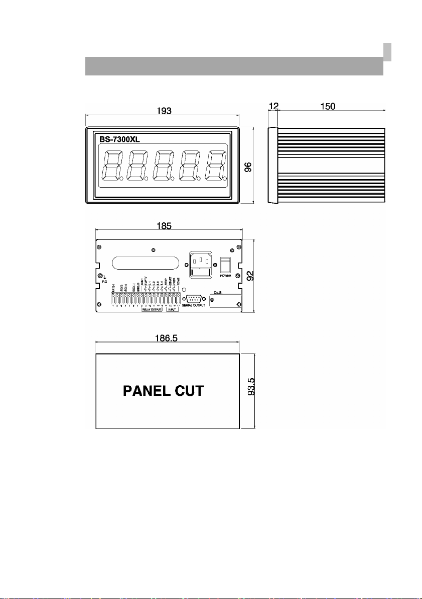
8=A9BG=CBG
8
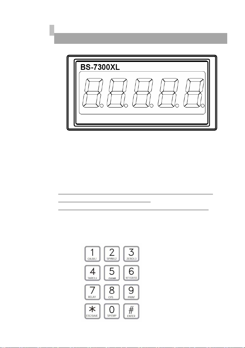
:fcbhDUbY`
%"8]gd`Um
Weight is Display.
&"?YmVcUfX
* The Key operating can be permitted or prohibited by dip switch.
* When pushing the key, it sounds "OK".
* Each Key works either a single function or compound functions.
A compound function key will be a command key when it push first
and According to the command key, the fixed value works its function,
The key to finish a input data is ENTER Key.
9
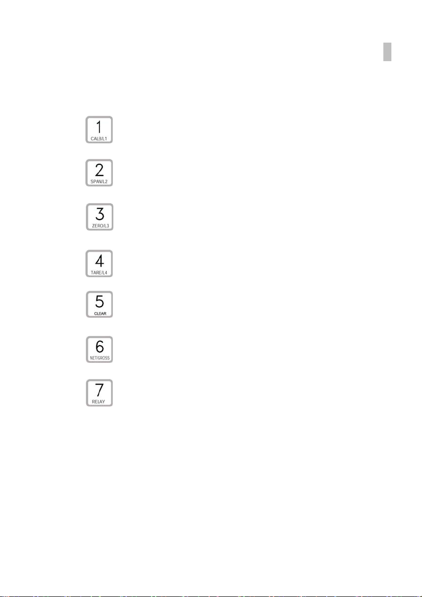
&!%"75@=6F5H=CB@C7?AcXY?Ym:ibWh]cbg
CALB mode : Simulative calibration or Number 1
LOCK mode : Number 1 or Analog output weight value
Set L1 range
CALB mode : Live calibration or Number 1
LOCK mode : Number 2
Set L2 range
CALB mode : ZERO or Number 3
LOCK mode : ZERO or Number 3
Set L3 range
CALB mode : Digital Filter Condition or Number 4
LOCK mode : TARE or Number 4
Set L4 range
CALB mode : Relay Mode Condition or Number 5
LOCK mode : HOLD Value Reset or Number 5
CALB mode : Minimum Grade Setting or Number 6
LOCK mode : NET/GROSS Conversion or Number 6
CALB mode : Motion Detect Condition Setting or Number 7
LOCK mode : Relay Range Setting or Number 7

10
CALB mode : Serial Interface Condition or Number 8
LOCK mode : Fall Range Setting or Number 8
CALB mode : Zero Tracking or Number 9
LOCK mode : Printer or Number 9
CALB mode : Decimal point setting or Number 0
LOCK mode : Number 0
Set EMPTY range
CALB mode : Data Input Cancel or SAVE
LOCK mode : Data Input Cancel or SAVE
CALB mode : Command or Start and set up display digit
LOCK mode : Command or Start and set up display digit

11
FYUfDUbY`
■ DCK9F : Power ON, OFF switch
It will be safe to use it after 10minuate for a precise measurements.
■ 57=B : Available to change AC110/220V with multiple.
Before setting up, please confirm the power voltage.
Please change the connect terminal of 110V/220V after
opening the cover
If you need to change. (It was settled with AC220V at the first)
Use a stable power supply AC110/220V ±10%, 50/60Hz
■ :IG9 : Please use the standard approved .
FUSE AC250V, 0.5A (a glass tube with small type)
■ :"; : Please earth it for safe.
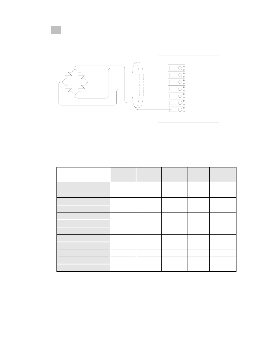
■ @C5879@@ Please connect the indicator connector with the wire of
load cell according to the color.
Pin no. SIGNAL
1 Load cell Input Voltage (-) EXC- (White)
3 Load cell output (-) SIG- (Blue)
4 Load cell output (+) SIG+ (Green)
6 Load cell Input Voltage (+) EXC+ (Red)
7 Shield SHIELD
12
The wire color of load cell according to a manufactures.
1
EXC-
3
SIG-
4
SIG+
6
EXC+
7
SHIELD
6CB;G<=B K<=H9 6@I9 ;F99B F98 G<=9@8
CAS, TMI, AND WHITE BLUE GREEN RED SHIELD
BLH BLACK RED WHITE GREEN YELLOW
INTERFACE BLACK WHITE GREEN RED SHIELD
KYOWA BLACK WHITE GREEN RED SHIELD
P.T. BLACK WHITE GREEN RED SHIELD
SHOWA BLUE BLACK WHITE RED SHIELD
SHINKOH BLACK WHITE GREEN RED SHIELD
TML BLACK GREEN WHITE RED SHIELD
TFAC BLUE BLACK WHITE RED YELLOW
HUNTLEIGH BLACK WHITE RED GREEN SHIELD
※ Because wire color may be different according to a manufacture and
load cell models. Please refer for the data sheet of load cell.
SIG- (Blue)
SHIELD
SIG+ (Green)
EXC+
EXC-
SIG+ SIG-
1
2
4
3
5
EXC+ (Red)
EXC- (White)
6
7
13
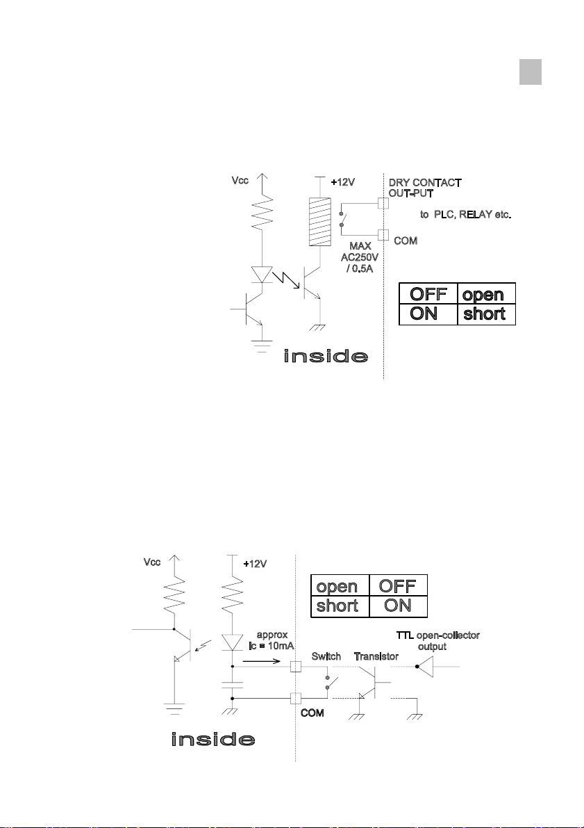
■ CIH!DIH : COM1, EMPTY, L 1, L 2, L 3, L4
Connect between COM terminal and OUTPUT terminal
With the earth of no electric power.
Please use the output data For a signal only, don’t use it for working.
Max earth capacity : AC250V / 0.5A
=B!DIH : COM2, STOP, START, ZERO
This key is to control a equipment from the outside .
Please connect between COM terminal and each input terminal .
Because the power of input terminal was connected with 12V voltage
From the inside.
* An electric current is about 10mA.
* Please make the minimum time to input a data with over 50mSEC.
14
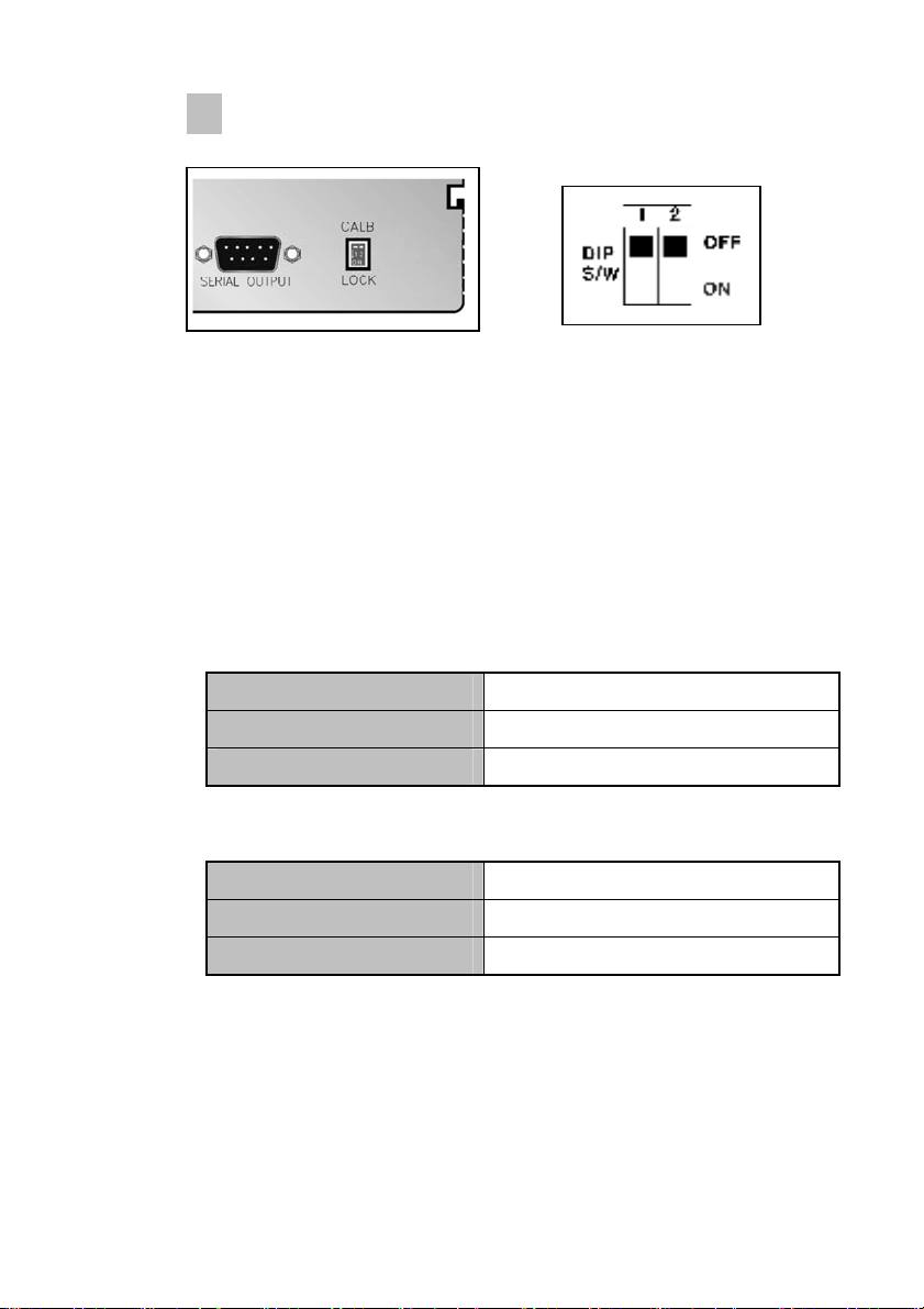
■ @C7?Gk]hW\
8]dg`]XYgk% : CALIBRATION & LOCK mode
SW 1 ON (Down) : Shift to lock mode. (weighing mode)
SW 1 OFF (Up) : Shift to calibration mode.
8]dg`]XYgk& : Not used
■ G9F=5@CIHDIH
GH5B85F8 Serial Interface : RS-232C
Cdh]cb–% Serial Interface : RS-422
Cdh]cb–& Serial Interface : Current Loop
■ Cdh]cb
Cdh]cb–' Analog Output : 0~10V
Cdh]cb–( Analog Output : 4~20mA
Cdh]cb–) Parallel Interface : BCD OUTPUT

15
=bghU``Uh]cb
☞ GENEANL RULES
- Avoid sudden Collision, vibration, temperature, water, wind
- Use a stable power supply 110V/220V ± 10% 50/60Hz
Set up voltage 220V
(Adjust the power voltage because the choice terminal of power is inside.)
- Connect and power off the switch when connecting the external
equipments.
- Ensure to earth Indicator to equipments
- Ensure to calibrate and set up it for operating.
* PARTS
- POWER CODE : 1EA
- FUSE : 1EA (PIPE TYPE 250V 0.5A SMALL TYPE)
- OPERATING MANUAL : 1EA
- A Stable Connector for Option installation.
▶ H9FA=B5@6@C7?
ઔ:IG9
INLET
FUSE : AC250V, 500mA

16
7U`]VfUh]cbacXY5WhiU`kY][\h
▣ What is Calibration?
Calibration is to adjust max weight, minimum division, decimal point
displayed to Indicator. To the actual weight worked by load cell.
☞ It should calibrated certainly when load cell or indicator will be
changed.
%" GD5B58>IGHA9BH
▣ what is span adjustment.
Span adjustment is to make the display value from "0" to max weight
consistent to the actual weight.
&" 7U`]VfUh]cbAYbi%GhYdr%$GhYd
1 Step : Calibration Mode Set
2 Step : Minimum Division Set
3 Step : Maximum Capacity Set &
Rated Output value Set
4 Step : Digital Filter Value Set
5 Step : Decimal Point Set
6 Step : Zero Calibration
7 Step : Span Calibration
8 Step : Relay mode Set
9 Step : Save
10 Step : END
GhYd%
- Function : 7U`]VfUh]cbAcXYGYh8]dgk]hW\gYh
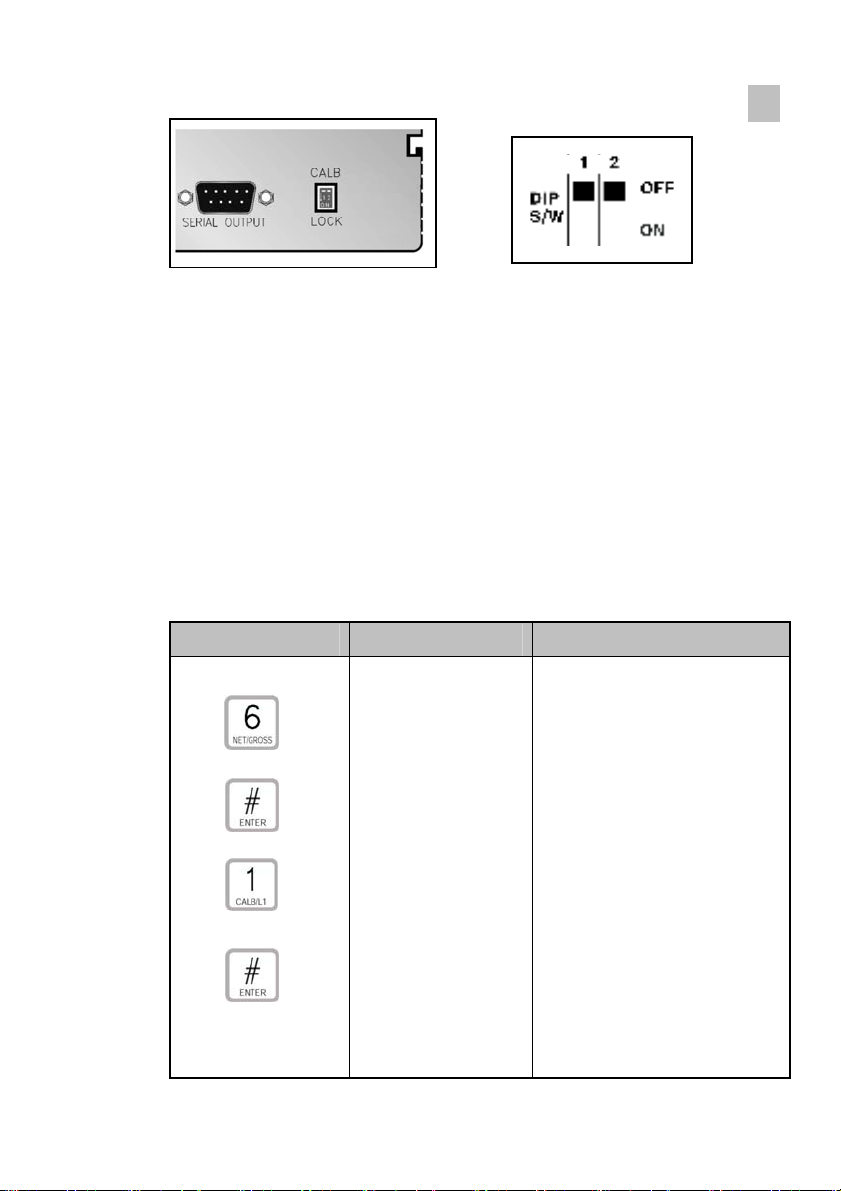
17
8]dg`]XYgk% : CALIBRATION mode
SW 1 OFF (Up) : Shift to calibration mode.
GhYd&
- Function : A]b]aia8]j]g]cbGYh
Range → 1~ 8
A step to set up a division value.
Also this value will be displayed as 1-2-5-10-20-50-100 by each key.
So, it will be go to the next step recording the position.
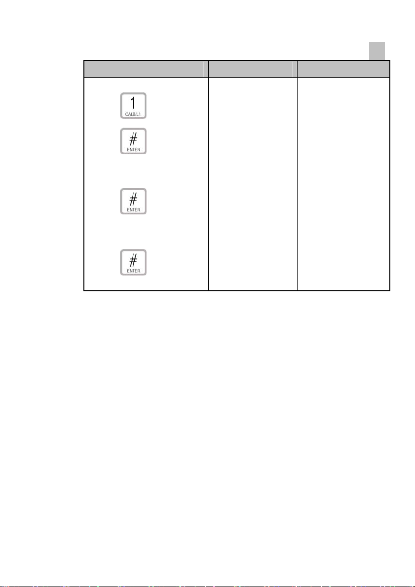
Key Display Description
x
x
1
0.000
0.001Kg (Decimal point: 3)
1 : 1,2,3,4,5…
2 : 2,4,6,8,10…
3 : 5,10,15,20,25…
4 : 10,20,30,40,50…
5 : 20,40,60,80,100…
6 : 50,100,150,200,250…
7 : 100,200,300,400,500…
8 : 200,400,800,1000…

18
☞ REF 1.The minimum division means the value of one division.
☞ REF 2. External resolution is obtained by division the min. division by the
maximum capacity. Set the resolution to be within 1/10,000.
GhYd'
- Function : AUl]aia7UdUW]hmGYh
Range → 1 ~ 99,900kg
A step to set up max. weight.
It can input the maximum weight as the end-user demands instead of
discretion number.
How to input is to push ENTER key after inputting discretion number.
♣ Don’t excess (A division ÷ Max. weight) with over 1/10,000
If accessing over 1/10,000,it will appear error.
- Function : FUhYXCihdihjU`iYGYh
Range → 1.0000 mV/V ~ 3.0000 mV/V
The display discretion number "r2.0000" (rated output 5figure)
Please input the value of standard weight for span adjustment by
numeric key.
How to input is to push
ENTER
key after inputting discretion number.
19
Key Display Description
Full Capacity Value Input
(xxxxx)
Load Cell Rated Output
Value Input (xxxxx)
xx.xxx
xx.xxx
xx.xxx
x.xxxx
x.xxxx
0.000
mV/V
☞ REF 1. The maximum capacity means the maximum weight that scale
can measure.
☞ REF 2. A data sheet is attached to a strain-gage sensor at the time of
purchase.
The data sheet provides data including:
capacity load(in kg, t, etc.)
rated output. Voltage(in mV/V)
non-linearity, Hysteresis, input resistance, output resistance and
zero balance.
Enter the capacity and the rated output value required for
equivalent input calibration into the BS-7300.
GhYd(
- Function : 8][]hU`:]`hYfGYhh]b[
Range → 1~ 9
Adjust the set value according to the condition how many times
converted digital value read and display.
How to input is to push
ENTER
key after inputting discretion
Table of contents
Other Bongshin Measuring Instrument manuals


Popular Measuring Instrument manuals by other brands

janitza
janitza UMG505 operating instructions

VOLTCRAFT
VOLTCRAFT LWT-04 operating instructions

Fluke
Fluke Biomedical MPS450 Operators Service manual

gaskatel
gaskatel Mini-HydroFlex user manual

Kobold
Kobold KEC-2 operating instructions

ATI Technologies
ATI Technologies C12-17 Operation and maintenance manual


