bonitron M3575T User manual

Model M3575T
Standard Duty Braking Transistor
Customer Reference Manual

Bonitron, Inc.
2
Bonitron, Inc.
Nashville, TN
An industry leader in providing solutions for AC drives.
ABOUT BONITRON
Bonitron designs and manufactures quality industrial electronics that improve the reliability of
processes and variable frequency drives worldwide. With products in numerous industries, and
an educated and experienced team of engineers, Bonitron has seen thousands of products
engineered since 1962 and welcomes custom applications.
With engineering, production, and testing all in the same facility, Bonitron is able to ensure its
products are of the utmost quality and ready to be applied to your application.
The Bonitron engineering team has the background and expertise necessary to design, develop,
and manufacture the quality industrial electronic systems demanded in today’s market. A strong
academic background supported by continuing education is complemented by many years of
hands-on field experience. A clear advantage Bonitron has over many competitors is combined
on-site engineering labs and manufacturing facilities, which allows the engineering team to have
immediate access to testing and manufacturing. This not only saves time during prototype
development, but also is essential to providing only the highest quality products.
The sales and marketing teams work closely with engineering to provide up-to-date information
and provide remarkable customer support to make sure you receive the best solution for your
application. Thanks to this combination of quality products and superior customer support,
Bonitron has products installed in critical applications worldwide.

Bonitron, Inc.
3
AC DRIVE OPTIONS
In 1975, Bonitron began working with AC inverter drive specialists at synthetic fiber plants to
develop speed control systems that could be interfaced with their plant process computers. Ever
since, Bonitron has developed AC drive options that solve application issues associated with
modern AC variable frequency drives and aid in reducing drive faults. Below is a sampling of
Bonitron’s current product offering.
WORLD CLASS PRODUCTS
Undervoltage Solutions
Overvoltage Solutions
Uninterruptible Power for Drives
(DC Bus Ride-Thru)
Voltage Regulators
Chargers and Dischargers
Energy Storage
Braking Transistors
Braking Resistors
Transistor/Resistor Combo
Line Regeneration
Dynamic Braking for Servo Drives
Common Bus Solutions
Portable Maintenance Solutions
Single Phase Power Supplies
3-Phase Power Supplies
Common Bus Diodes
Capacitor Formers
Capacitor Testers
Power Quality Solutions
Green Solutions
12 and 18 Pulse Kits
Line Regeneration

M3575T
4
1. INTRODUCTION............................................................................................................. 7
1.1. Who Should Use...........................................................................................................7
1.2. Purpose and Scope......................................................................................................7
1.3. Manual Version and Change Record............................................................................7
Figure 1-1: Typical M3575T Module..........................................................................................7
1.4. Symbol Conventions Used in this Manual and on Equipment.......................................8
2. PRODUCT DESCRIPTION................................................................................................ 9
2.1. Related Products..........................................................................................................9
2.2. Part Number Breakdown ..............................................................................................9
Figure 2-1: Example of M3575T Part Number Breakdown .......................................................9
Table 2-1: AC Voltage Rating Codes ........................................................................................9
Table 2-2: Chassis Determination...........................................................................................10
Table 2-3: Special Options ......................................................................................................11
2.3. General Specifications................................................................................................11
Table 2-4: General Specifications Table .................................................................................11
2.4. General Precautions and Safety Warnings.................................................................12
3. INSTALLATION INSTRUCTIONS...................................................................................... 13
3.1. Environment...............................................................................................................13
3.2. Unpacking ..................................................................................................................13
3.3. Mounting.....................................................................................................................13
3.4. Conduit Cover Installation for M3 and M4 Chassis .....................................................13
Figure 3-1: Conduit Cover Installation for M3 and M4 chassis ...............................................14
3.5. Wiring and Customer Connections.............................................................................14
3.5.1. Power Wiring ................................................................................................................14
Table 3-1: Power Wiring Specifications...................................................................................15
3.5.2. Control Interface Wiring................................................................................................16
Table 3-2: Control Interface Wiring Specifications..................................................................16
3.6. Typical Configurations................................................................................................17
Figure 3-2: Typical Power Interconnection Diagram...............................................................17
Figure 3-3: Customer Connections .........................................................................................18
4. OPERATION ............................................................................................................... 19
4.1. Functional Description................................................................................................19
4.2. Features.....................................................................................................................19
4.2.1. Indicators ......................................................................................................................19
4.2.2. Terminal Strip I/O..........................................................................................................19
4.3. Pre-Power Checks......................................................................................................20
4.4. Startup Procedure and Checks...................................................................................20
4.5. Operational Adjustments ............................................................................................20
5. MAINTENANCE AND TROUBLESHOOTING ...................................................................... 21
5.1. Periodic Testing..........................................................................................................21
5.2. Maintenance Items.....................................................................................................21
5.3. Troubleshooting..........................................................................................................21
5.3.1. DC bus light not illuminated..........................................................................................21
5.3.2. Blown DC bus fuse.......................................................................................................22
5.3.3. Fan runs constantly ......................................................................................................22
5.3.4. Fan doesn’t run .............................................................................................................22
5.3.5. Control Ready contacts won’t close .............................................................................23
5.3.6. Module over-temp, or module seems too hot...............................................................23
5.3.7. Drive trips on overvoltage.............................................................................................23
5.3.8. Braking light flickers......................................................................................................23
5.3.9. Active braking light stays on all the time.......................................................................24

Table of Contents
5
5.3.10. Attached Drive Will Not Precharge...............................................................................24
5.4. Technical Help –Before you call ................................................................................24
6. ENGINEERING DATA ................................................................................................... 25
6.1. Ratings Charts............................................................................................................25
Table 6-1: Module Ratings ......................................................................................................25
6.2. Watt Loss ...................................................................................................................26
Table 6-2: Watt Loss ...............................................................................................................26
6.3. Certifications...............................................................................................................27
6.4. UL 508A Short Circuit Current Rating.........................................................................27
6.5. Fuse Sizing and Rating...............................................................................................27
Table 6-3: Recommended Fuses............................................................................................27
6.6. DC Bus Length Limits.................................................................................................27
Table 6-4: Maximum Inductance for DC Link Cable ...............................................................28
6.7. Dimensions and Mechanical Drawings .......................................................................29
Figure 6-1: M3 Chassis Dimensional Outline Drawing............................................................29
Figure 6-2: M4 Chassis Dimensional Outline Drawing............................................................30
Figure 6-3: B5 Chassis Dimensional Outline Drawing ............................................................31
Figure 6-4: B7 Chassis Dimensional Outline Drawing ............................................................32
Figure 6-5: MTW 3575-CVR-30U Conduit Cover Dimensional Outline ..................................33
Figure 6-6: MTW 3575-CVR-30 Conduit Cover Dimensional Outline.....................................33
6.8. Block Diagram............................................................................................................34
Figure 6-7: Block Diagram.......................................................................................................34
7. APPENDIX.................................................................................................................. 35
7.1. Application Notes........................................................................................................35
7.1.1. Sizing Your Braking Requirements...............................................................................35
7.1.2. Status Contact Connection Notes ................................................................................36
Figure 7-1: Typical Status Contact Wiring with Input Contactor..............................................38
Figure 7-2: Typical Status Contact Wiring with Drive Interlock Control ..................................39
7.1.3. Common Bus Notes......................................................................................................40

M3575T
6
This page is intentionally left blank.

User’s Manual
7
1. INTRODUCTION
1.1. WHO SHOULD USE
This manual is intendedfor use by anyone who is responsiblefor integrating, installing,
maintaining, troubleshooting, or using this equipment with any AC drive system.
Please keep this manual for future reference.
1.2. PURPOSE AND SCOPE
This manual is a user’s guide for the M3575T standard duty braking transistor. It will
provide the user with the necessary information to successfully install, integrate, and
use the M3575T.
In the event of any conflict between this document and any publication and/or
documentation related to the AC drive system, the latter shall have precedence.
1.3. MANUAL VERSION AND CHANGE RECORD
Additional models were added in rev 07 of this manual.
A new setpoint option and additional dimensional outlines were added in rev 07a.
Connection drawings were updated in rev 07b.
Wiring specifications were updated in rev 07c.
Updates to the Indicators were made in rev 07d.
The manual template was updated in rev 07e.
Table 6-1 and Figure 6-4 were updated in rev 07f.
Table 6-1 and Section 7.1.1.3 were updated in rev 07g.
Tables 2-2 and 3-1 and Figure 6-3 were updated in rev 07h.
Section 4.2.21 Status Contacts was updated in rev 07i.
Information regarding conduit cover installation was added in rev 07j.
Figure 1-1: Typical M3575T Module

M3575T
8
1.4. SYMBOL CONVENTIONS USED IN THIS MANUAL AND ON
EQUIPMENT
Earth Ground or Protective Earth
AC Voltage
DC Voltage
DANGER!
Electrical Hazard - Identifies a statement that indicates a shock
or electrocution hazard that must be avoided.
DANGER!
DANGER: Identifies information about practices or
circumstances that can lead to personal injury or death,
property damage, or economic loss.
CAUTION!
CAUTION: Identifies information about practices or
circumstances that can lead to property damage, or economic
loss. Attentions help you identify a potential hazard, avoid a
hazard, and recognize the consequences.
CAUTION!
Heat or burn hazard - Identifies a statement regarding heat
production or a burn hazard that should be avoided.
User’s Manual
9
2. PRODUCT DESCRIPTION
The need for regenerated voltage control occurs in applications where the frequency of
an AC motor at times exceeds that of its adjustable speed drive. In this case, the motor
acts as a generator. The energy generated by the motor must be dissipated as heat, or
returned to the power line. If this energy is not controlled, the motor may run with high
peak voltages, the energy may be dissipated as heat in the motor, or the drive may trip on
an over-voltage condition.
For applications where this condition occurs infrequently, dissipating the energy as heat
through resistive braking control can be the most cost-effective solution.
2.1. RELATED PRODUCTS
The model M3575T series of braking products is designed to provide resistive braking
control for applications utilizing a standard AC drive with a fixed DC bus. These
modules have been designed for use with remotely mounted resistive loads such as
the model M3575R or M3775RK resistive load modules.
For higher duty cycle applications, consider the M3452 series of braking transistor
modules.
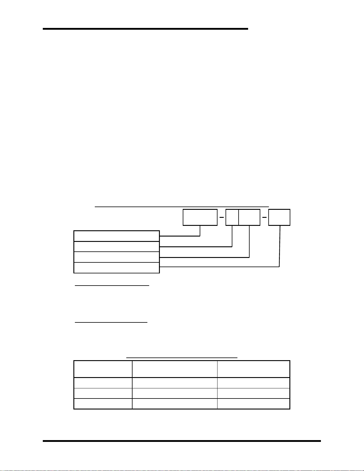
2.2. PART NUMBER BREAKDOWN
Figure 2-1: Example of M3575T Part Number Breakdown
BASE MODEL NUMBER
The Base Model Number M3575T indicates that the unit incorporates the braking
transistor and its control circuitry only. An external resistive load is required for proper
function of the braking module.
AC VOLTAGE RATING
The AC voltage rating of the braking unit should match the input AC line voltage to the
AC drive used with the braking module. This rating is represented by a letter code as
shown in Table 2-1.
Table 2-1: AC Voltage Rating Codes
AC VOLTAGE
RATING CODE
AC VOLTAGE
NOMINAL AC LINE
DC BUS
TRIGGER LEVEL
L
230VAC
375VDC
E
400VAC
620VDC
H
460VAC
750VDC
BASE MODEL NUMBER
AC VOLTAGE RATING
DC CURRENT RATING
SPECIAL OPTIONS
M3575T
H
200
Nxxx

M3575T
10
DC CURRENT RATING
The DC current rating indicates the maximum DC current level safely handled by the
braking unit. This rating is represented numerically such that a value of “15” would
indicate that the braking unit has a peak current rating of 15 amps DC. The RMS
current rating of the unit depends on the application of the braking module. RMS
current ratings have been calculated for braking as well as for overhauling
applications. See Section 7.1.1 for application sizing assistance.
CHASSIS INFORMATION
Chassis size is determined by the module rating. For additional information, please
see Table 6-1 for ratings charts and Table 6-4 for chassis dimensions.
Table 2-2: Chassis Determination
230VAC
MODEL NUMBER
CHASSIS
DIMENSIONS H” X W” X D”
M3575T-L15
M3
12.75 x 3.00 x 8.70
M3575T-L30
M3
12.75 x 3.00 x 8.70
M3575T-L60
M4
12.75 x 4.00 x 8.70
M3575T-L125
B5
17.75 x 5.50 x 8.00
M3575T-L150
B5
17.75 x 5.50 x 8.00
M3575T-L200
B7
17.75 x 7.00 x 8.00
M3575T-L300
B7
17.75 x 7.00 x 8.00
M3575T-L600
B7
17.75 x 7.00 x 8.00
400VAC
MODEL NUMBER
CHASSIS
DIMENSIONS H” X W” X D”
M3575T-E15
M3
12.75 x 3.00 x 8.70
M3575T-E30
M3
12.75 x 3.00 x 8.70
M3575T-E75
M4
12.75 x 4.00 x 8.70
M3575T-E125
B5
17.75 x 5.50 x 8.00
M3575T-E150
B5
17.75 x 5.50 x 8.00
M3575T-E200
B7
17.75 x 7.00 x 8.00
M3575T-E300
B7
17.75 x 7.00 x 8.00
M3575T-E600
B7
17.75 x 7.00 x 8.00
460VAC
MODEL NUMBER
CHASSIS
DIMENSIONS H” X W” X D”
M3575T-H15
M3
12.75 x 3.00 x 8.70
M3575T-H30
M3
12.75 x 3.00 x 8.70
M3575T-H75
M4
12.75 x 4.00 x 8.70
M3575T-H125
B5
17.75 x 5.50 x 8.00
M3575T-H150
B5
17.75 x 5.50 x 8.00
M3575T-H200
B7
17.75 x 7.00 x 8.00
M3575T-H300
B7
17.75 x 7.00 x 8.00
M3575T-H600
B7
17.75 x 7.00 x 8.00

User’s Manual
11
SPECIAL OPTIONS
Table 2-3: Special Options
CODE
DESCRIPTION
Nxxx
A 3 digit setpoint is entered when a non-standard setpoint is required
C
Optional conduit cover for M3 and M4 chassis only.
2.3. GENERAL SPECIFICATIONS
Table 2-4: General Specifications Table
PARAMETER
SPECIFICATION
Adjustments
Factory calibrated - no field adjustments necessary
Connections
Drive DC bus
Resistors
Fault contact
Enclosure
Type 1
Status Output
Form-C contact rated at 1.0 Amp at 24VDC
or 0.5 Amp at 120VAC –Normally closed
Status Output opens on:
Open load
Over temperature
Transistor failure
Panel Indicators
DC Bus
Active Braking
Drive Voltage
For use with 230VAC, 400VAC, and 460VAC drive systems
Control Power
Derived from DC bus voltage:
100-400VDC required for 230VAC drives
320-800VDC required for 400VAC drives
450-800VDC required for 460VAC drives
Braking Current
15 –600A
(Use Bonitron M3452 for applications requiring 600+ Amps)
Turn-on Voltage
375VDC (for 230VAC drives)
620VDC (for 400VAC drives)
750VDC (for 460VAC drives)
Maximum On-Time
60 seconds
Duty Cycle
20% maximum for braking applications
6.67% maximum for overhauling applications
(Use Bonitron M3452 for applications requiring higher duty
cycles)
UL Approval
Units rated up to and including 75 amps peak are UL approved
Refer to UL file number E204386
Operating Temp
0ºC to 40º C
Storage Temp
-20 ºC to +65ºC
Humidity
Below 90% non-condensing
Atmosphere
Free of corrosive gas and conductive dust

M3575T
12
2.4. GENERAL PRECAUTIONS AND SAFETY WARNINGS
DANGER!
HIGH VOLTAGES M AY BE PRESENT!
NEVER ATTEMPT TO OPERATE THIS PRODUCT WITH THE
ENCLOSURE COVER REMO VED!
FAILURE TO HEED THESE WARNINGS MAY RESULT IN
SERIOUS BODILY INJURY OR DEATH!
CAUTION!
THIS PRODUCT WILL GENERATE HIGH AMBIE NT
TEMPERATURES DURING OPE RATION.
THIS PRODUCT SHOULD BE INST ALLED ACCORDINGL Y ON
NON-FLAMMABLE SURFACES W ITH CLEARANCES OF AT
LEAST TW O INCHES IN ALL DIRECTI ONS.
ALWAYS ALLOW AMPLE TIME FOR THE UNIT TO C OOL
BEFORE ATTEMPTING SE RVICE ON THIS PRODUC T.
NO USER-SERVICE ABLE PARTS AR E CONTAINED WI THIN THIS
PRODUCT.INOPERABLE UNITS SHOULD BE REPLACED OR
RETURNED F OR EVAL UATION AND/OR REPAIR BY QUALIFIED
TECHNICIANS.
BEFORE ATTEMPTING INS TALLATION OR REM OVAL OF THIS
PRODUCT,BE SURE TO REVIEW ALL DRIVE AND/OR
RESISTIVE LOAD DOCUM ENTATION FOR PERTINENT SAFETY
PRECAUTIONS .
INSTALLATION AND/OR REMOVAL OF THIS PRODUCT SHOULD
ONLY BE ACCOM PLISHED BY A QUALIFIED ELECTRICIAN IN
ACCORDANCE WITH NATIONAL ELECTRICAL CODE OR
EQUIVALENT REGULATIO NS.
ATTENTION!
A
T
T
E
N
T
I
O
N
!
Important Notice about drives with DC link chokes!
DURING BRAKING S ITUATIONS,ENERGY STORED IN A
DRIVE’S DC LINK CHOKES CAN CREATE EXTREME OVER-
VOLTAGE CONDITIONS F OR BRAKING TRANSISTOR
MODULES.TO AVOID THESE CONDIT IONS,DC CONNECTIONS
FROM BRAKING TRANSISTOR MODULES T O THE DRIVE
SYSTEM SHOULD ALWAYS BE MADE DIRECTLY IN PARAL LEL
WIT H T HE DRIVE’S FI LTER CAPACITORS.THESE MODULES
SHOULD NEVER BE CONNECTED IN SERIES WITH A DRIVE’S
DC LINK CHOKES.
BE SURE TO REV IEW ALL PERTINENT AC DRIVE
DOCUMENTATION TO ENSURE THAT THE PROPER
CONNECTIONS ARE USED.
CONT ACT THE DRIVE MANUFACT URER OR EQUIPMENT
SUPPLIER FOR ASSI ST ANCE WITH DRIVE CONNECTIONS.
ANY QUESTIONS AS TO APPLICATION, INSTALLATION, OR SERVICE
SAFETY SHOULD BE DIRECTED TO THE EQUIPMENT SUPPLIER.

User’s Manual
13
3. INSTALLATION INSTRUCTIONS
3.1. ENVIRONMENT
The installation site for the module should be chosen with several considerations in
mind.
The mounting surface must be non-flammable, as the unit will generate high
ambient temperatures during typical operation.
The unit will require a minimum clearance of two inches in all directions around it.
The unit will require adequate protection from the elements.
3.2. UNPACKING
Prior to installation, please verify that the product received matches the product that
was ordered and that there is no physical damage to the unit. If the wrong product
was received or is damaged in any way, please contact the supplier from which it was
purchased.
3.3. MOUNTING
WARNING!
Installation and/or removal of this product should only be
accomplished by a qualified electrician in accordance with National
Electrical Code or equivalent regulations.
Proper installation of the Model M3575T standard duty braking transistor module
should be accomplished following the steps outlined below. Be sure to refer to your
AC drive’s instruction manual as you perform these steps. Please direct all installation
inquiries that may arise during the installation and startup of this braking product to
your supplier or system integrator.
Once the installation site has been selected as outlined in Section 3.1, the unit should
be mounted in place using two or four ¼ inch diameter bolts or studs. Mounting
dimensions vary by unit chassis size. Refer to Table 2-2 and Section 6.7 for unit and
mounting dimensions.
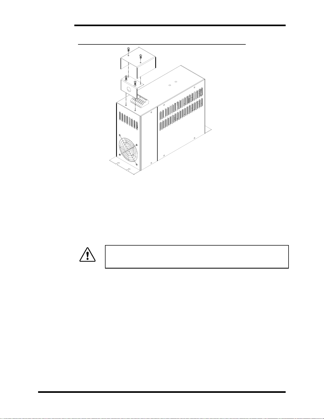
3.4. CONDUIT COVER INSTALLATION FOR M3 AND M4 CHASSIS
The conduit cover is an optional cover for the M3575T with current ratings 15, 30, 60,
and 75A. The conduit cover option is designated by Cin the part number. See
Section 6.4 for conduit cover dimensions.
1. Inspect the chassis and conduit cover metalwork, MTW 3575-CVR-30 and MTW
3575-CVR-30U.
2. Install MTW 3575-CVR-30U below terminal strip. Rout wires through the circular
opening.
3. Install MTW 3575-CVR-30 according to Figure 3-2.
M3575T
14
Figure 3-1: Conduit Cover Installation for M3 and M4 chassis
3.5. WIRING AND CUSTOMER CONNECTIONS
3.5.1. POWER WIRING
This section provides information pertaining to the field connection of the DC
bus inputs to the M3575T and M3575R resistive braking modules. Actual
connection points andterminal numbers for the AC drive module will be found
in the documentation provided with the drive. Be sure to review all pertinent
drive and system documentation as well as the power connection notes listed
below before proceeding.
WARNING!
Only qualified electricians should perform and maintain the
interconnection wiring of this product. All wiring should be done in
accordance with local codes.

User’s Manual
15
Table 3-1: Power Wiring Specifications
MODEL NUMBER
CHASSIS
TERMINAL
MIN WIRE
AWG
MAX WIRE
AWG
TORQUE
M3575T-L15
M3575T-L30
M3575T-L60
M3575T-E15
M3575T-E30
M3575T-E75
M3575T-H15
M3575T-H30
M3575T-H75
M3, M4
DC+, DC-,
RES+, RES-
16 AWG
12 AWG
0.4-0.6 Nm
3.5-5.3 lb-in
M3575T-L125
M3575T-L150
M3575T-E125
M3575T-E150
M3575T-H125
M3575T-H150
B5
DC+, DC-,
RES+, RES-
12 AWG
8 AWG
0.8-1.6 Nm
7-14 lb-in
M3575T-L200
M3575T-L300
M3575T-E200
M3575T-E300
M3575T-H200
M3575T-H300
B7
(200A, 300A)
DC+, DC-,
RES+, RES-
6 AWG
2 AWG
2.5-5.0 Nm
22-44 lb-in
M3575T-L600
M3575T-E600
M3575T-H600
B7
(600A)
DC+, DC-,
RES+, RES-
4 AWG
2/0 AWG
14 Nm
120 lb-in
Attention!
The braking kit is rated in peak amperage. The wiring only needs to be
sized to handle the RMS current value which can be found in Table 6-1 in
Section 6 of this manual.
3.5.1.1. DC BUS CONNECTION
WARNING!
DC bus polarity must be correct! Connecting the DC bus with the
polarity reversed will cause damage to the equipment!
As a general rule, 30 feet (10m) is the maximum total buswork or
cable thatthe choppershould be mountedfrom the drive. This means
that the actual installation distance should be 15 feet (5m), as the
cable must go out and back. If you must connect the choppers farther
away, see Section 6.6 DC Bus Length Limits.
The braking transistor must be connected directly to the DC bus filter
capacitors of the drive.
Figure 3-2 is an example of the terminals that may be available in
your installation. Not all of the terminals may be on your drive. Refer
to the drive manufacturer's manual or technical documents to locate
the proper terminals. Your drive will have different terminal markings
depending on manufacturer and drive series.

M3575T
16
Ensure that the polarity of the connection is correct. Incorrect polarity
will effectively short the DC bus of the drive, and can cause severe
damage to the drive, load resistor, and the braking transistor.
The proper terminals to attach the braking transistor are marked +
and - on Figure 3-2.
The terminals marked BR+ and BR- are intended for the internal
braking transistor. If the Bonitron external braking transistor is
hooked to the terminals, the braking transistor will not operate
properly. In some cases, it may cause drive failure.
The terminals marked X and Y are intended for connection of a DC
link choke. If the Bonitron braking transistor is connected to the
terminals marked X and Y in Figure 3-2, switching resonances
caused by the DC link choke will destroy the braking transistor. If the
Bonitron braking transistor is connected between X and Y, the drive
will not operate.
If the braking transistor is connected to the terminals marked A and
B in Figure 3-2, switching resonances caused by the lack of filter
capacitance during precharge will destroy the braking transistor.
3.5.1.2. RESISTOR CONNECTION
The polarity of the resistor connections is not critical; however, it is critical
that the resistor be connected to the proper terminals. Improper hookup
can lead to the resistor being connected directly across the DC bus, which
will cause severe overheating and drive stress.
Minimum load resistance requirements listed in Table 6-1: Module
Ratings in Section 6 of this manual MUST be followed when selecting a
resistive load for use with the M3575T unit.
3.5.1.3. GROUNDING REQUIREMENTS
All units come equipped with either a ground terminal or ground stud that
is connected to the module chassis. Ground the chassis in accordance
with local codes. Typically, the wire gauge will be the same as is used to
ground the attached drive.
3.5.2. CONTROL INTERFACE WIRING
Table 3-2: Control Interface Wiring Specifications
TERMINAL
FUNCTION
ELECTRICAL
SPECIFICATIONS
MIN WIRE
AWG
MAX WIRE
AWG
TORQUE
TS 5-6
Status
Contacts
1.0 A at 24 VDC
0.5 A at 120 VAC
16 AWG
12 AWG
0.4-0.6 Nm
3.5-5.3 lb-in

User’s Manual
17
3.6. TYPICAL CONFIGURATIONS
Figure 3-2: Typical Power Interconnection Diagram

M3575T
18
Figure 3-3: Customer Connections
MOTOR
Input Rectifier
ØA
ØB
ØC
Precharge (2)
+
X Y
DC Link Choke (1)
BR+ BR-
Internal Brake
Transistor
connection
(Not Used)
-
Load Bank
Resistor
Bonitron Braking
Transistor
DC+
RES
DC-
RES
Notes:
(1) Precharge connections may not be external
(2) Choke may be internal to drive
A B
DC Bus Filter
Capacitors
Output
Inverter

User’s Manual
19
4. OPERATION
4.1. FUNCTIONAL DESCRIPTION
The M3575T module controls the bus voltage of a variable frequency drive by
transferring energy to a resistor.
When the drive’s DC bus voltage exceeds a fixed setpoint, the dynamic braking
transistor module’s control electronics turns on an IGBT transistor connecting a
resistive load across the DC bus. When the DC bus drops below another threshold,
the IGBT turns off.
The standard turn on setpoint for the M3575T is 375VDC for 230VAC systems,
620VDC for 400VAC systems, and 750VDC for 460VAC systems. See Section 2.2
Special Options for non-standard turn on voltages.
4.2. FEATURES
4.2.1. INDICATORS
4.2.1.1. DC BUS
The green DC Bus indicator illuminates when the voltage between the
DC+ and DC- terminals is greater than 40VDC.
CAUTION!
Do not use this light as an indication that the DC Bus is safe to work
on! Always check the DC bus with a working voltmeter before
servicing equipment, as the DC bus light may be broken!
4.2.1.2. ACTIVE BRAKING
The red indicator illuminates when the chopper IGBT is on. When the
drive is idle, this light should not be on. During braking, this light will be
on or flashing, depending on the amount of braking energy.
4.2.2. TERMINAL STRIP I/O
See Figure 3-1.
4.2.2.1. STATUS CONTACTS
The Status Contacts TS 5&6 will be closed unless there is a fault.
These contacts OPEN on the following conditions:
Failed IGBT (power transistor)
Open Load
Overtemperature in module
If one of these conditions exists, the module will not operate, and the DC
bus will not be regulated through the braking resistor.
CAUTION!
Bonitron braking transistor modules are designed to be used with
stand-alone or common DC bus drive/inverter systems with bus
capacitors. When using the Bonitron modules on common bus
systems, special considerations may apply. Refer to and review the
Application Notes found in Section 7.1.3 prior to energizing this type
of system!

M3575T
20
4.3. PRE-POWER CHECKS
Ensure that all connections are tight, DC bus polarity is correct, and that all customer
wiring is of the proper size for operational requirements. Check for exposed
conductors that may lead to inadvertent contact. Verify the load bank is properly sized
for the application. The ohmic value and wattage rating of the load bank are important
for proper and reliable system operation! Remember; do not operate the module
with less than its minimum ohmsvalue rating! See Section 7for sizing information.
4.4. STARTUP PROCEDURE AND CHECKS
Apply AC power to the drive system and the dynamic braking transistor module. Do
not start the motors on the system.
On the dynamic braking transistor module, verify the following:
Green DC Bus indicator is ON.
Red Active Braking indicator is OFF!Immediately turn off all power if the
indicator is ON to avoid possible load bank overheating and/or other equipment
damage
Verify the drive system DC bus voltage, and make sure it is within tolerance for the
drive system.
Verify the DC current flow through the load bank is zero amps. Even though the
Red Active Braking indicator is OFF, any significant current flow could indicate
incorrect connections or damaged equipment. Immediately turn off all power to
avoid possible load bank overheating and/or other equipment damage if current
flow is indicated!
Note: Depending on the type of measuring equipment used, small currents
could just be noise pickup and could be ignored.
Check status contacts to ensure they are all closed. This indicates that the module
does not have a fault.
If any of the above conditions are not as indicated, turn off all power and allow ample
time for all system energy sources to discharge. Verify that all voltages are below
40V with a meter! Check all wiring connections and jumper configurations. Refer to
the Section 5 of this manual for more information. For further assistance, contact
Bonitron.
Once the pre-checks are complete, the drive system can be enabled. Once the drive
system is operational, run themotors with light deceleration, and decrease the braking
time until the red Active Braking indicator lights.
4.5. OPERATIONAL ADJUSTMENTS
No adjustments are necessary for this module. All regulation points are factory
adjusted, and should not be changed in the field. If your module is not functioning
properly, refer to troubleshooting in Section 5 of this manual or contact Bonitron for
assistance.
Table of contents
Other bonitron Circuit Breaker manuals

Popular Circuit Breaker manuals by other brands

Siemens
Siemens Sentron 3VA9157-0FK Series operating instructions

Siemens
Siemens SION operating instructions

Schrack
Schrack MC4-XU Series installation instructions

ABB
ABB Emax 2 Retrofill Installation and maintenance guide

OEZ
OEZ MINIA MMR-X3-001-A230 Instructions for use

ABB
ABB SACE Emax 2 Instructions for use


