manuals.online logo
Brands
  1. Home
  2. •
  3. Brands
  4. •
  5. WEG
  6. •
  7. Circuit Breaker
  8. •
  9. WEG DWA 630 User manual

WEG DWA 630 User manual

I
1
0
Interruptor cerrado.
Disjuntor ligado.
Circuit-breaker in “ON”
position.
Interruptor abierto por
intervención de relés.
Para volver a cerrar el
interruptor, se deberá llevar
la palanca hacia "2"
(posición extrema en
el rearme).
Disjuntor desarmado por
intervenção de reles. Para
religar o disjuntor deve-se
levar a alavanca até a posição
“2” (Posição de rearme).
"I"
LINEA DE INTERRUPTORES
LINHA DE DISJUNTORES
CIRCUIT-BREAKER LINE
CONTROLE DE RECEBIMENTO:
O disjuntor é fornecido com os parafusos de fi-
xação e com os acessórios especificados no
pedido, embalados adequadamente em uma
caixa de papelão. Também deverá estar dentro
da embalagem as instruçôes de montagem con-
tendo as distâncias mínimas, seções dos cabos
ou barras recomendados e as prescrições de
instalação e manutenção.
Se ao desembalar, houver alguma irregulari-
dade no produto, notifique a WEG (diretamente,
ou por intermédio do fornecedor ou representan-
te) o mais breve possível.
ARMAZENAMENTO:
Armazenar o disjuntor em um ambiente seco,
livre de pó e de agentes corrosivos, conser-
vando sua embalagem original.
INSTALAÇÃO:
Instalar o disjuntor em um ambiente seco, sem
pó, sem substâncias corrosivas que possam
afetar o seu funcionamento. Além disto, deverá
estar livre de vibrações ou golpes que possam
ser causados por pessoas ou coisas.
Em caso de instalação em lugar não recomen-
dado, deve ser providenciado um quadro ou
caixa fechada para a instalação.
CHECKING ON RECEIPT:
The circuit-breaker is provided with fixing
(mounting) screws and the accessories
specified on the order with proper packaging.
The circuit-breaker will be provided with
directions for its installation, minimum dis-
tances, cross sections of cables or recom-
mended bars and maintenance.
Carry out a visual check that the unit is in
good conditions on the connections and on
the protection setting. Don’t hesitate to con-
tact WEG for any further information you
may require.
STORAGE:
The circuit-breaker should be stored inside
the package, in a clean, dust-free, non-corro-
sive place, even if only for a few days.
INSTALLATION:
The circuit-breaker must be installed in a
dry, dust-free, non-corrosive place not su-
ceptible to shocks or vibration. If the insta-
llation place is not according to the re-
commended, install the circuit-breaker into
an enclosure or cubicle with an appropriate
protection degree.
Circuit-breaker tripped
due to release operation.
To reset the circuit-breaker,
move the lever to position
“2” (lever end position to
reset the operating
mechanism)
and after to position “I”.
.
"1”
Interruptor abierto.
Disjuntor desligado.
Circuit-breaker in “OFF”
position.
"O"
108.0
2
30 30
(3-2 POL.) 210,0
(4POL.) 280,0
947 - 2
I E C
066 0
V D E
AB - 1
N E M A
DWA 800N
MR
CAT. A
Ue V kA
220/240
380/415
440
500
690
250
Icu
50-60
Hz
Ics = 100% Icu
I
630/800
4000/8000
20
65
35
35
30
25
Iu = 800 A
Ue = 690 V
T = 45 ºC
DWA 800N-800
r
I
0,9
1
0,8
x Ir
TEST
Irm
x Ir
Irm
t
I
r
I
5
10
r
Im
x Ir
Irm
x Ir
5
10
5
10
30 100
“DWA 630/ DWA 800“
CONTROL DE RECEPCION:
El interruptor se provee con: los tornillos de fi-
jación, y los accesorios especificados en el pe-
dido, embalados adecuadamente en una caja
de cartón.
El interruptor también será provisto con las
prescripciones para su instalación, distancias
mínimas, secciones de cables o barras reco-
mendadas e instructivo de mantenimiento.
Si al desembalar el producto hubiere alguna
irregularidad, notifique a WEG (directamente o
a través del proveedor o representante) a la
brevedad.
ALMACENAJE:
Es aconsejable almacenar el interruptor en un
ambiente seco, libre de polvo y de elementos
contaminantes, conservando su embalaje original.
INSTALACION:
Deberá ser instalado en un ambiente seco,
sin polvo ni sustancias corrosivas que puedan
afectar su funcionamiento. Además deberá es-
tar resguardado de vibraciones o golpes que
puedan ser causados por personas o cosas.
En caso de que el lugar no sea el recomenda-
do para la instalación, esta deberá efectuarse
en un gabinete o caja tipo estanco.
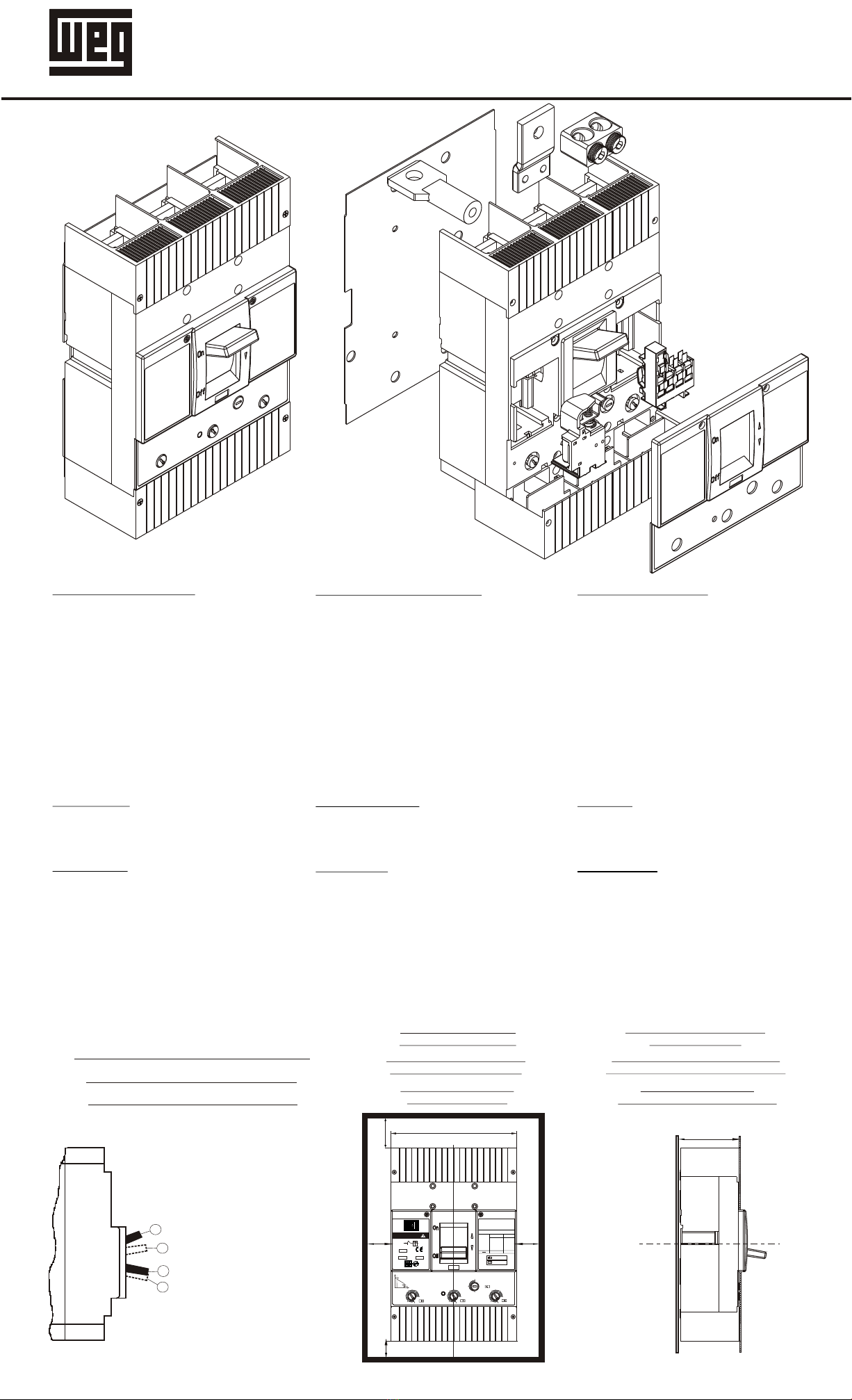
CARACTERÍSTICAS GENERALES CARACTERÍSTICAS GERAIS GENERAL CHARACTERISTICS
INSTRUCCIONES DE MONTAJE INSTRUÇÕES DE MONTAGEM ASSEMBLY INSTRUCTIONS
POSITIONS OF THE OPERATING LEVER
MINIMUN DISTANCES
FROM THE WALLS
DISTÂNCIAS MÍNIMAS ATÉ
AS PAREDES EXTERNAS
DISTANCIAS MINIMAS
DESDE LAS PAREDES
MINIMUN DISTANCES
BETWEEN PANEL AND FRONT
DISTÂNCIA MÍNIMA ENTRE A CHAPA
DE MONTAGEM E A PORTA DO PAINEL
DISTANCIA MINIMA ENTRE
PANEL Y FRENTE
POSIÇÕES DA ALAVANCA DE MANOBRA
POSICIONES DE LA PALANCA DE MANIOBRA
13.513.5 230230 13.513.5
7070
7777
7070
257257
103103
231231
323323
3333 3333
1313
1313
7070
280 4POLOS280 4POLOS
7070
210 3POLOS210 3POLOS
3535
35357070
SECCIONES DE CABLES Y BARRAS RECOMENDADAS CONFORME A IEC - 60947 - 1
SEÇÕES DE CABOS E BARRAS RECOMENDADOS CONFORME NORMA IEC - 60947 - 1
CABLES AND BARS SIZES RECOMMENDED ACCORDING TO IEC - 60947 - 1
www.weg.net
CORRIENTE NOMINAL
CORRENTE NOMINAL
RATED CURRENT
SECCION DEL CABLE
SEÇÃO DE CABOS
CABLE SIZE
A
SECCION DE BARRA
SEÇÃO DE BARRAS
BAR SIZE
2
mm
(Cu)
2
mm
(Cu)
250 320 400 500 630 800
120
20 x 6
185
40 x 5
1 x 240
2 x 95
40 x 6
2 x 150
50 x 6
2 x 185
50 x 8
2 x 240
3 x 150
2(50 x 5)
50 x 10
AGUJEROS PARA
FIJACIÓN INTERRUPTOR
70
=230=
RM 5
78
82,5
104
FURAÇ O PARA
FIXAÇ O DO DISJUNTOR
Ã
Ã
DRILLING FOR FIXING
CIRCUIT BREAKER
CALADO DE
PUERTA
FURAÇ O DA
PORTA
Ã
DRILLING OF DOOR
14,714,7
88
8383
22.522.5 106.5106.5
9898
113113
140140
14.714.7
108108
88
2525
5050
11.511.5
1313
12.512.5
RM12x1.75RM12x1.75
RM8x1.25RM8x1.25
2525
DIMENSIONES GENERALES
DIMENSÕES GERAIS
GENERAL DIMENSIONS
NEUTRONEUTRO
NEUTRALNEUTRAL
On
Off
RECOMENDAÇÕES PARA AS CONEXÕES
Para realizar as conexões, as superficies de contato
deverão estar planas, limpas, sem rebarbas, mar-
cas e vestígios de oxidação. Pode-se utilizar uma
lima fina ou esmeril para a remoção dessas imperfei-
ções. Para a remoção de gordura ou graxa das su-
perfícies, utilizar um pano com álcool ou solvente.
Em caso de utilização de cabos para as conexões, é
recomendado o emprego de terminais adequados.
Em caso de conexões com barras de cobre (para
temperatura ambiente superior a 40º C, ou em am-
bientes contaminados), recomenda-se pratear as
zonas de contato das barras com os terminais dos
disjuntores. O torque de aperto não deverá ex-
ceder: para M-8=20 Nm, para M-12=50Nm.
IMPORTANTE
Para que exista um bom contato entre as conexões,
é necessário manter apertados os parafusos e porcas
correspondentes.
É recomendado reapertar regularmente os parafusos
dos prensa cabos.
MANUTENÇÃO
Em condições normais de uso não é necessário ma-
nutenção. No caso de existir erosão dos contatos
por curto-circuito, será necessário reparar as su-
perfícies dos mesmos com uma lima fina ou esmeril.
NOTA: Para realizar operações de manutenção
deve-se desligar o disjuntor e desconectar a energia
de alimentação.
RECOMENDACION PARA LAS CONEXIONES
Para realizar las conexiones, las superficies en contac-
to deberán estar planas y limpias, eliminando rebabas,
marcas y rastros de oxidación utilizando para ello una
lima fina o tela esmeril.
Para quitar la grasitud de las superficies utilizar un pa-
ño con alcohol o solvente.
En caso de utilizar conexiones con cable, es aconseja-
ble el empleo de terminales adecuadas de identación.
El par de apriete no deberà exceder para M-8=20Nm,
para M-12 = 50 Nm.
IMPORTANTE
Para que exista un buen contacto en las conexiones
será necesario mantener apretados los tornillos y tuer-
cas correspondientes.
Así mismo, se aconseja volver a apretar regularmente
los prisioneros en el caso de conexión con prensacable.
MANTENIMIENTO
En condiciones normales de uso no requiere manteni-
miento, pero, en caso que se produzca erosión de los
contactos por cortocircuito, será necesario reparar
la superficie de los mismos con una lima fina o tela
esmeril.
NOTA: Para realizar cualquier operación de manteni-
miento se deberá abrir el interruptor y cortar la ener-
gía de alimentación.
DIRECTIVES FOR CONNECTIONS
For proper connection, the contact surfaces should
be flat, clean, without rough edges, marks and signs
of oxidation.
To remove excess grease on the surfaces, use a cloth
with some solvent.
In case of using connection with cables, is recommen-
ded to use suitable terminals.
The tight torque shall not be exceed: for M-8 = 20
Nm, for M-12 = 50 Nm.
IMPORTANT
For good contact among connections, it is necessary
to use corresponding screws and nuts tight.
In case of using connections with terminal lugs, it is
recommended to tight regularly the screws.
MAINTENANCE
In normal conditions of use it is not necessary main-
tenance. In case of contacts erosion by short-circuit,
it will be necessary repair their surface.
NOTE: Before proceeding with any work of mainte-
Nance, operate the circuit-breaker to “OFF” position
and disconnect power in this equipment.

This manual suits for next models

1

Other WEG Circuit Breaker manuals

WEG EHU ACW400 User manual

WEG

WEG EHU ACW400 User manual

WEG UBW120 User manual

WEG

WEG UBW120 User manual

WEG DWB100 User manual

WEG

WEG DWB100 User manual

WEG FHU ACW125 User manual

WEG

WEG FHU ACW125 User manual

WEG UBW250 User manual

WEG

WEG UBW250 User manual

WEG ACW400 User manual

WEG

WEG ACW400 User manual

WEG UBW800S User manual

WEG

WEG UBW800S User manual

WEG DWB800 User manual

WEG

WEG DWB800 User manual

WEG MPW25 User manual

WEG

WEG MPW25 User manual

WEG DWA1250 User manual

WEG

WEG DWA1250 User manual

WEG DW-161 User manual

WEG

WEG DW-161 User manual

WEG MPW18 User manual

WEG

WEG MPW18 User manual

WEG UBW400 User manual

WEG

WEG UBW400 User manual

WEG CWB40 80 Series User manual

WEG

WEG CWB40 80 Series User manual

WEG MRX ACW100 User manual

WEG

WEG MRX ACW100 User manual

WEG DWB400 User manual

WEG

WEG DWB400 User manual

WEG AM DWA400 User manual

WEG

WEG AM DWA400 User manual

WEG MRX ACW400 User manual

WEG

WEG MRX ACW400 User manual

WEG ACW Series User manual

WEG

WEG ACW Series User manual

WEG UBW2500 User manual

WEG

WEG UBW2500 User manual

WEG CESTARI Worm Gearbox line User manual

WEG

WEG CESTARI Worm Gearbox line User manual

WEG ACW101V User manual

WEG

WEG ACW101V User manual

WEG DWB600 User manual

WEG

WEG DWB600 User manual

WEG SSW900-CRS485-W User manual

WEG

WEG SSW900-CRS485-W User manual

Popular Circuit Breaker manuals by other brands

Siemens PL 50 manual

Siemens

Siemens PL 50 manual

ABB ReliaMod RMS212522LRLR installation instructions

ABB

ABB ReliaMod RMS212522LRLR installation instructions

GenInterlock GE-100A instructions

GenInterlock

GenInterlock GE-100A instructions

Allis-Chalmers LA-600 Instruction book

Allis-Chalmers

Allis-Chalmers LA-600 Instruction book

Westinghouse F-11 instructions

Westinghouse

Westinghouse F-11 instructions

GE AK-1-15 Series instructions

GE

GE AK-1-15 Series instructions

Linear Technology DC1198B-A Demo Manual

Linear Technology

Linear Technology DC1198B-A Demo Manual

OEZ LFN Instructions for use

OEZ

OEZ LFN Instructions for use

FuseBox AFDD060630B Technical data

FuseBox

FuseBox AFDD060630B Technical data

Leviton LBHPL installation instructions

Leviton

Leviton LBHPL installation instructions

Moeller Xcomfort CJAU-01 Assembly instructions

Moeller

Moeller Xcomfort CJAU-01 Assembly instructions

Eaton Series NRX Instruction leaflet

Eaton

Eaton Series NRX Instruction leaflet

ABB Emax manual

ABB

ABB Emax manual

Moeller NZMS 64 Series installation instructions

Moeller

Moeller NZMS 64 Series installation instructions

ABB SACE Tmax XT manual

ABB

ABB SACE Tmax XT manual

ABB SACE Emax 2 quick start guide

ABB

ABB SACE Emax 2 quick start guide

Siemens 3VA24 H Series operating instructions

Siemens

Siemens 3VA24 H Series operating instructions

Siemens 3WX31 83-8 Series operating instructions

Siemens

Siemens 3WX31 83-8 Series operating instructions

manuals.online logo
manuals.online logoBrands
  • About & Mission
  • Contact us
  • Privacy Policy
  • Terms and Conditions

Copyright 2025 Manuals.Online. All Rights Reserved.