TE 4020 User manual
TE CONNECTIVITY SENSORS///MODEL 4020 & 4030 ACCELEROMETER 05/2016
Page 1
OPERATION MANUAL
MODEL 4020 & 4030
ACCELEROMETER

MODEL 4020 & 4030 ACCELEROMETER
TE CONNECTIVITY SENSORS/// MODEL 4020 & 4030 ACCELEROMETER 05/2016
Page 2
WARRANTY
Measurement Specialties, Inc. accelerometers are warranted during a period of one year from date of shipment to original purchaser to be free
from defects in material and workmanship. The liability of Seller under this warranty is limited to replacing or repairing any instrument or
component thereof which is returned by Buyer, at his expense, during such period and which has not been subjected to misuse, neglect,
improper installation, repair, alteration, or accident. Seller shall have the right to final determination as to the existence and cause of a defect.
In no event shall Seller be liable for collateral or consequential damages. This warrant is in lieu of any other warranty, expressed, implied, or
statutory; and no agreement extending or modifying it will be binding upon Seller unless in writing and signed by a duly authorized officer.
RECEIVING INSPECTION
Every Measurement Specialties, Inc. accelerometer is carefully inspected and is in perfect working condition at the time of shipment. Each
accelerometer should be checked as soon as it is received. If the unit is damaged in any way, or fails to operate, a claim should immediately
be filed with the transportation company.
SERVICE CONCERNS
If a Measurement Specialties, Inc. instrument requires service, first contact the nearest Measurement Specialties, Inc. representative. They
may be able to solve the problem without returning the unit to the factory. If it is determined that factory service is required, call Customer
Service at the regional headquarters for an RMA number before return.
RETURNS
All units being returned to the factory require an RMA (Return Material Authorization) number before they will be accepted. This number may
be obtained by calling Customer Service at the regional headquarters with the following information; model number(s), quantity, serial
number(s), and symptoms of the problem, if being returned for service. You must include the original purchase order number if under
warranty.
RECALIBRATION SERVICES
The Vibration Sensors Design Center and its two manufacturing facilities in China and France offer factory re-calibration services for
Piezoresistive, Piezoelectric and Integrated Electronics Piezoelectric (IEPE, ISOTRON, ICP, etc.) accelerometers. NIST (US), DKD
(Germany), COFRAC (France) traceable calibration services on sensitivity at 100 Hz (102 or 120 Hz in Europe) and full frequency sweeps are
offered. Contact the regional headquarters for pricing information.

MODEL 4020 & 4030 ACCELEROMETER
TE CONNECTIVITY SENSORS/// MODEL 4020 & 4030 ACCELEROMETER 05/2016
Page 3
2x ¼ or M6 mounting screws
Torque to 18 lb-in (2.0 Nm)
DESCRIPTION
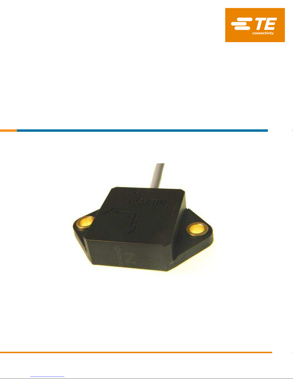
The Model 4020 & 4030 are low noise, signal conditioned DC accelerometers packaged in a durable molded housing with an integral cable
assembly. The accelerometers are offered in ±2g & ±6g ranges with a nominal 0-200Hz bandwidth and an operating temperature range of -
40°C to +85°C. The model 4020 is a dual axis configuration while model 4030 is a triaxial configuration.
INSTALLATION
The model 4020 & 4030 accelerometers are designed to be screw mounted. The following guidelines should be followed when screw
mounting these accelerometers.
The mounting surface should be clean and free of any residue or foreign material.
The mounting surface should be smooth and flat.
Torque screws to recommended limits using steel washers under the heads of the mounting screws. Use manual torque wrench (do not
use electric tools).

MODEL 4020 & 4030 ACCELEROMETER
TE CONNECTIVITY SENSORS/// MODEL 4020 & 4030 ACCELEROMETER 05/2016
Page 4
WIRING
The accelerometers are designed to be operated from 5-30Vdc excitation and provide a 0.5 to 4.5V full scale output. The output is DC-coupled
and should be used in single-ended mode. The sensor and electronics are fully contained in an internal Faraday cage which is connected to
the cable shield (floating with respect to circuit ground) for RFI protection.
A 2.5Vdc bias will be present on the output leads and the output of the accelerometer will be 0.5-4.5V full scale. The accelerometer should be
connected to the interface circuitry as detailed below.
Biaxial model 4020 wiring diagram
Triaxial model 4030 wiring diagram

MODEL 4020 & 4030 ACCELEROMETER
TE CONNECTIVITY SENSORS/// MODEL 4020 & 4030 ACCELEROMETER 05/2016
Page 5
CABLE ROUTING
The model 4020 & 4030 accelerometers incorporate a PVC jacketed cable with an integral shield. The cable assembly should be properly
secured at regular intervals during testing. It is recommended to use clamps, wax, or tape to secure the cable to minimize cable motion that
can add noise to the output signal. The initial attachment should be within two to three inches of the accelerometer.
Avoid routing cables near high-voltage wires and also ground the shield at the signal conditioner to minimize ground loops.
SELF-TEST OPERATION
The model 4020 & 4030 accelerometers incorporate a self-test feature. This feature is activated by grounding the self-test lead (gray). The
corresponding shift in bias output is shown in table below.
Range (g)
±2
±6
Self Test Output Change (mV)
X = +210 ±90
X = +70 ±30
Y = -210 ±90
Y = -70 ±30
Z = -340 ±190
Z = -110 ±65
The self-test bias shift takes place no matter the orientation of the accelerometer. Sensitivity is unaffected. For normal operation the gray lead
floats and is not connected.
NOISE FLOOR SPECIFICATIONS
The model 4020 & 4030 accelerometers incorporate a LP filtered output for a high output signal. The noise specifications for this
accelerometer are detailed in table below.
FULL SCALE
RATING
(g-pk)
SENSITIVITY
(mV/g)
±5% AMPL
PASSBAND
(Hz)
PASSBAND
NOISE
(µVrms)
SPECTRAL NOISE
(µg-rms/√Hz)
DYNAMIC RANGE
(dB)
2
1000
200
600
51
67
6
333
200
240
42
75
MODEL 4020 & 4030 ACCELEROMETER
TE CONNECTIVITY SENSORS/// MODEL 4020 & 4030 ACCELEROMETER 05/2016
Page 6
te.com/sensorsolutions
Measurement Specialties, Inc., a TE Connectivity company.
Measurement Specialties (MEAS), American Sensor Technologies (AST), TE Connectivity, TE Connectivity (logo) and EVERY CONNECTION COUNTS are trademarks. All other logos,
products and/or company names referred to herein might be trademarks of their respective owners.
The information given herein, including drawings, illustrations and schematics which are intended for illustration purposes only, is believed to be reliable. However, TE Connectivity makes
no warranties as to its accuracy or completeness and disclaims any liability in connection with its use. TE Connectivity‘s obligations shall only be as set forth in TE Connectivity‘s Standard
Terms and Conditions of Sale for this product and in no case will TE Connectivity be liable for any incidental, indirect or consequential damages arising out of the sale, resale, use or
misuse of the product. Users of TE Connectivity products should make their own evaluation to determine the suitability of each such product for the specific application.
© 2016 TE Connectivity Ltd. family of companies All Rights Reserved.
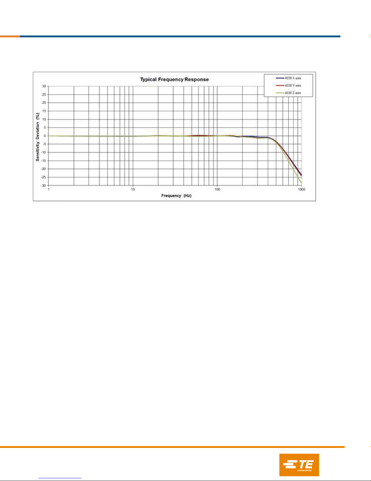
FREQUENCY RESPONSE CURVES
The typical frequency response curves for the model 4030 accelerometers are illustrated below.
Measurement Specialties, Inc.,
a TE Connectivity Company
Vibration Sensors Design Center
32 Journey, Suite 150
Aliso Viejo, CA 92656, USA
Tel: +1 949 716 7324
NORTH AMERICA
EUROPE
ASIA
Measurement Specialties, Inc.,
a TE Connectivity Company
1000 Lucas Way
Hampton, VA 23666
United States
Tel: +1 757 766 1500
MEAS Deutschland GmbH
a TE Connectivity Company
Impasse Jeanne BENOZZI
CS 83 163, 31027 Toulouse Cedex 3, France
Tel: +33 (0) 582 08 22 00
Measurement Specialties China Ltd.,
a TE Connectivity Company
No. 26, Langshan Road
Shenzhen High-tech Park (North)
Nanshan District, Shenzhen 518057
China
Phone: +86-755-3330-5088
This manual suits for next models
1
Table of contents
Other TE Measuring Instrument manuals


