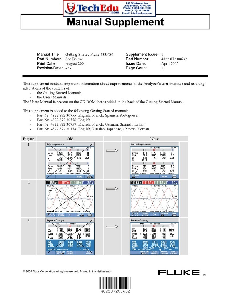
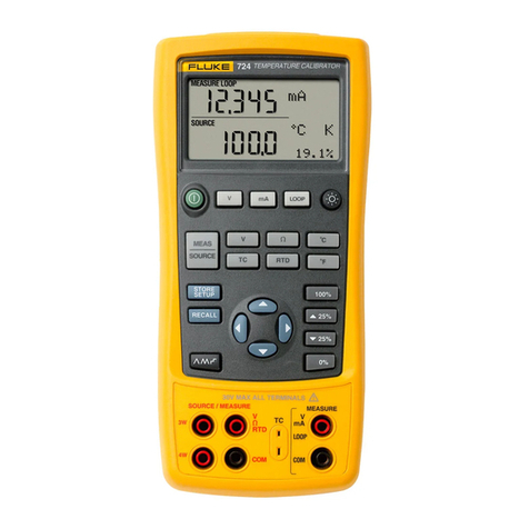
Fluke SMFT-1000 Use and care manual

SMFT-1000
Multifunction PV Analyzer
Calibration Manual
6/2023 (English)
©2023 Fluke Corporation. All rights reserved.
Specifications are subject to change without notice.
All product names are trademarks of their respective companies.

LIMITED WARRANTY AND LIMITATION OF LIABILITY
Each Fluke product is warranted to be free from defects in material and workmanship under normal use
and service. The warranty period is 3 years and begins on the date of shipment. Parts, product repairs,
and services are warranted for 90 days. This warranty extends only to the original buyer or end-user
customer of a Fluke authorized reseller, and does not apply to fuses, disposable batteries, or to any
product which, in Fluke's opinion, has been misused, altered, neglected, contaminated, or damaged by
accident or abnormal conditions of operation or handling. Fluke warrants that software will operate
substantially in accordance with its functional specifications for 90 days and that it has been properly
recorded on non-defective media. Fluke does not warrant that software will be error free or operate
without interruption.
Fluke authorized resellers shall extend this warranty on new and unused products to end-user customers
only but have no authority to extend a greater or different warranty on behalf of Fluke. Warranty support is
available only if product is purchased through a Fluke authorized sales outlet or Buyer has paid the
applicable international price. Fluke reserves the right to invoice Buyer for importation costs of repair/
replacement parts when product purchased in one country is submitted for repair in another country.
Fluke's warranty obligation is limited, at Fluke's option, to refund of the purchase price, free of charge
repair, or replacement of a defective product which is returned to a Fluke authorized service center within
the warranty period.
To obtain warranty service, contact your nearest Fluke authorized service center to obtain return
authorization information, then send the product to that service center, with a description of the difficulty,
postage and insurance prepaid (FOB Destination). Fluke assumes no risk for damage in transit. Following
warranty repair, the product will be returned to Buyer, transportation prepaid (FOB Destination). If Fluke
determines that failure was caused by neglect, misuse, contamination, alteration, accident, or abnormal
condition of operation or handling, including overvoltage failures caused by use outside the product’s
specified rating, or normal wear and tear of mechanical components, Fluke will provide an estimate of
repair costs and obtain authorization before commencing the work. Following repair, the product will be
returned to the Buyer transportation prepaid and the Buyer will be billed for the repair and return
transportation charges (FOB Shipping Point).
THIS WARRANTY IS BUYER'S SOLE AND EXCLUSIVE REMEDY AND IS IN LIEU OF ALL OTHER
WARRANTIES, EXPRESS OR IMPLIED, INCLUDING BUT NOT LIMITED TO ANY IMPLIED WARRANTY OF
MERCHANTABILITY OR FITNESS FOR A PARTICULAR PURPOSE. FLUKE SHALL NOT BE LIABLE FOR ANY
SPECIAL, INDIRECT, INCIDENTAL OR CONSEQUENTIAL DAMAGES OR LOSSES, INCLUDING LOSS OF
DATA, ARISING FROM ANY CAUSE OR THEORY.
Since some countries or states do not allow limitation of the term of an implied warranty, or exclusion or
limitation of incidental or consequential damages, the limitations and exclusions of this warranty may not
apply to every buyer. If any provision of this Warranty is held invalid or unenforceable by a court or other
decision-maker of competent jurisdiction, such holding will not affect the validity or enforceability of any
other provision.
11/99
Fluke Corporation
P.O. Box 9090
Everett WA 98206-9090
U.S.A.
Fluke Europe B.V.
P.O. Box 1186
5602 BD Eindhoven
The Netherlands
i
Table of Contents
Title Page
Introduction................................................................................................................................... 1
Contact Fluke ............................................................................................................................... 1
Safety Information...................................................................................................................... 1
Specifications .............................................................................................................................. 1
Static Awareness ........................................................................................................................ 2
Maintenance ................................................................................................................................. 3
Battery Replacement........................................................................................................ 3
Product Disposal................................................................................................................4
Equipment Requirements ........................................................................................................ 5
Performance Tests..................................................................................................................... 5
Visual Inspection ................................................................................................................ 5
RLO .............................................................................................................................................................................. 6
VOC (Open-Circuit Voltage) ............................................................................................ 8
ISC (Short-Circuit Current)............................................................................................... 10
RINS Insulation Resistance Method I (No Voltage) ................................................. 12
RINS Insulation Resistance Method I (With Voltage).............................................. 16
RINS Insulation Resistance Method II (No Current) ................................................ 18
RINS Insulation Resistance Method II (With Current)............................................. 22
Diode Voltage...................................................................................................................... 24
Surge Protection Device (SPD)..................................................................................... 26
AC/DC Voltage.................................................................................................................... 27
AC/DC Current (SMFT only) ........................................................................................... 29
SMFT-1000 DC and AC Current with Clamp ........................................................... 31
Hysteresis .................................................................................................................... 31
Setup for Ascending/Descending DC and AC Current
Test Procedure .......................................................................................................... 31
Ascending DC Test................................................................................................... 37
Descending DC Test ................................................................................................ 37
50 Hz and 60 Hz AC Current Test........................................................................ 37
AC/DC Power....................................................................................................................... 37
Calibration Adjustment and Repair ...................................................................................... 41
Replaceable Parts....................................................................................................................... 41

ii
SMFT-1000
Calibration Manual

1
Introduction
XW Warning
Read Safety Information before you use the Product.
This manual explains the Performance Tests for the SMFT-1000 (the Product or PV Analyzer).
See the SMFT-1000 Users Manual for usage information.
Contact Fluke
Fluke Corporation operates worldwide. For local contact information, go to our website:
www.fluke.com
To register your product, or to view, print, or download the latest manual or manual
supplement, go to our website: www.fluke.com/productinfo
+1-425-446-5500 fluke-info@fluke.com
Safety Information
General Safety Information is in the printed Safety Information document that ships with the
Product and at www.fluke.com. More specific safety information is listed where applicable.
A Warning identifies hazardous conditions and procedures that are dangerous to the user. A
Caution identifies conditions and procedures that can cause damage to the Product or the
equipment under test.
Specifications
Complete specifications are at www.fluke.com. See the SMFT-1000 Users Manual.

SMFT-1000
Calibration Manual
2
Static Awareness
Semiconductors and integrated circuits can be damaged by electrostatic discharge during
handling. This notice explains how to minimize damage to these components.
1. Understand the problem.
2. Learn the guidelines for proper handling.
3. Use the proper procedures, packaging, and bench techniques.
Follow these practices to minimize damage to static sensitive parts.
XW Warning
To prevent electric shock or personal injury. De-energize the product and all
active circuits before opening a product enclosure, touching or handling any
PCBs or components.
Minimize handling.
Handle static-sensitive
parts by non-conductive
edges.
Do not slide static-
sensitive components
over any surface.
When removing plug-in
assemblies, handle only
by non-conductive
edges.
Never touch open-edge
connectors except at a
static-free work station.
Keep parts in the original
containers until ready for
use.
Use static shielding
containers for handling
and transport.
Avoid plastic, vinyl, and
polystyrene foam in the
work area.
Handle static-sensitive
parts only at a static-free
work station.
Put shorting strips on the
edge of the connector to
help protect installed
static-sensitive parts.
Use anti-static type
solder extraction tools
only.
Use grounded-tip
soldering irons only.

Multifunction PV Analyzer
Maintenance
3
Maintenance
Periodically wipe the case with a damp cloth and mild detergent. Do not use abrasives or
solvents. Dirt or moisture in the terminals can affect readings.
XW Warning
To prevent possible electrical shock, fire, or personal injury:
Voltages as high as 1 kV are used in this procedure. Handle electrical wires with
caution.
Have an approved technician repair the Product.
Battery Replacement
Replace the batteries with six AA batteries. Alkaline batteries are supplied with the Tester.
XW Warning
To prevent possible electrical shock, fire, or personal injury:
Remove the test leads and any input signals before you replace the battery.
Install ONLY specified replacement fuses with the amperage, voltage, and speed
ratings shown in the Specifications section of the Users Manual.
To replace the batteries (see Figure 1):
1. Push to turn off the PV Analyzer.
2. Remove the test leads from the terminals.
3. To remove the battery door, use a standard-blade screwdriver to turn the battery door
screws (x3) one-quarter turn counterclockwise.
4. Push the release latch and slide the battery holder out of the Tester.
5. Replace the batteries.

SMFT-1000
Calibration Manual
4
6. Replace the battery holder and the battery door.
7. Turn the battery door screws one-quarter turn clockwise to fasten the door.
Figure 1. Battery Replacement
Product Disposal
Dispose of the Product in a professional and environmentally sound manner:
Delete personal data on the Product before disposal.
Remove batteries that are not integrated into the electrical system before disposal and
dispose of batteries separately.
If this Product has an integral battery, put the entire Product in the electrical waste
WFF 630 mA
1000 V IR 30 kA

Multifunction PV Analyzer
Equipment Requirements
5
Equipment Requirements
Tab l e 1 is a list of the standard equipment for the performance tests.
Performance Tests
Performance tests make sure that the Product operates within the published specifications.
Fluke recommends performance tests periodically.
In this section the Product is called the DUT (device under test). Use these verification
performance tests to make sure the values indicated on the DUT correspond, as closely as
possible, with the actual measurement values.
If the product fails any part of the performance test, see Calibration Adjustment and Repair.
Visual Inspection
Before you do the performance tests:
1. Visually inspect the DUT for signs of physical damage.
If you find a problem, make notes of the damage and perform the as-found calibration
before correction.
2. Examine the test lead sockets for debris or damage. If dirt is found, gently use a cotton
swab to remove the contaminants.
3. Make sure the DUT and all test equipment have sufficient warm-up time in accordance with
the manufacturer's specifications.
Table 1. Standard Equipment
Equipment Required Characteristics Recommended Model/Part
Number
Multi-Product Calibrator 4.5-digit resolution, 20 A output Fluke 552xA, or equivalent
Multifunction Electrical Tester
Calibrator NA Fluke 532xA
Current Source 20 A output Keithley 2260B-30-36
Digital Multimeter 5.5-digit dual-display Fluke 8808A
High Voltage Power Supply 1 kV output Keithley 2290-5
Wired Coil 25-turn 52120A/COIL3KA
Test Lead low-thermal EMF (up to 500 mA) 5730A-7002
Test Lead high current (up to 20 A) Pomona B-12-X
Test Lead shielded (up to 1000 V) Fluke Shielded Calibration
Test Leads/PN 216239

SMFT-1000
Calibration Manual
6
To reduce thermal EMF errors, use low-thermal leads when you calibrate voltage functions and
low-resistance functions (<50 kΩ). To calibrate current functions, use the appropriately rated
cables for the current. Currents as high as 20 A will be generated. When calibrating high-
resistance functions (>50 kΩ), use shielded test leads to reduce electromagnetic interference.
RLO
To verify the resistance of earthing and equipotential bonding conductors:
1. Set all equipment and the DUT to standby mode.
2. Connect two low-thermal EMF test leads to the DUT, one at green connector (ground) and
one at yellow connector.
3. Short the two test leads together at the furthest point from the DUT.
4. Disconnect all other test leads.
5. Turn the rotary switch on the DUT to .
6. Push to zero the test leads.
If the DUT shows an error that the lead resistance cannot exceed 3 Ω, recheck that the
leads have good contact and try again.
Note
When zeroing and calibrating the RLO function, allow at least 10 seconds for any
thermal EMFs to dissipate when you move test leads from one socket to another.
Thermal EMFs have a significant contribution to the error present in the lower ohm
measurements.
7. Disconnect the test leads from each other and connect the DUT green connector (ground)
to the green (PE) port on 532xA and DUT yellow connector to the blue (N) port on 532xA.
See Figure 2.

Multifunction PV Analyzer
Performance Tests
7
Figure 2. RLO Connections
8. Set the 532xA calibrator to output the first resistance test point (see Tab le 2) and set to
2-wire, ground bond resistance (Z GND) output mode.
9. Push on the DUT to set the One Shot mode.
10. Push OPER on the 532xA to set the operate mode, if necessary, and wait for the calibrator
to stabilize.
Table 2 . RLO Te s t Po i n t s
Range Te s t P o i n t s
[Ω]
Display Reading [Ω]
Lower Limit Upper Limit
0 Ωto 19.99 Ω
0.35 0.32 0.38
0.96 0.92 1.00
1.70 1.65 1.75
17.00 16.64 17.36
20 Ωto 199.0 Ω90.0 88.0 92.0
170.0 166.4 173.6
200 Ωto 2000 Ω
470 445 496
900 853 947
1700 1613 1787
ANALYZER
Fluke 5320A
Fluke SMFT-1000
LO
METER
,
L
,
L
+/-

SMFT-1000
Calibration Manual
8
11. Momentarily push on the DUT.
Wait for the DUT to finish both the + and - measurements. Record the + and - indications on
the DUT in the test record. Also record the nominal value displayed on the 532xA as it may
be slightly different from the intended nominal. If applicable, recalculate the limits based on
the nominal value and the published specifications.
Note
Ignore the red X or green . They do not indicate a pass or fail for this calibration.
12. Set the 532xA calibrator to output the next resistance test point (see Ta b le 2).
13. Repeat steps 10 through 12 for all test points.
14. Set the 532xA calibrator to standby mode.
VOC (Open-Circuit Voltage)
To v e r i f y :
1. Set all equipment and the DUT to standby mode.
2. Connect low-thermal EMF test leads from DUT red connector to 552xA NORMAL port and
DUT blue connector to the 552xA black port below NORMAL port. Disconnect all other test
leads (see Figure 3).
Figure 3. VOC (Open-Circuit Voltage) Connections
3. Turn the rotary switch on the DUT to VOC/ISC.
POWER
0•
123
456
789
ENTER
M
k
mVHz FIELD
EDIT
/
+
F
OPR EARTH SCOPEEXGRD MENU
PREV
SHIFT
RESET
CE
SETUP
REF
NEW
TC
MEAS
F
n
p
p
W
dBm sec
C
A
MULT
xDIV
MODES
MORE
STBY
5522A CALIBRATOR
ANALYZER
Fluke 5522A
Fluke SMFT-1000

Multifunction PV Analyzer
Performance Tests
9
4. Set the 552xA calibrator to output the first voltage test point (see Tab le 3).
5. Push OPER on the 552xA to set the operate mode, if necessary, and wait for the calibrator
to stabilize.
6. Record the indication from the DUT in the test record.
7. Set the 552xA calibrator to output the next voltage test point (see Ta b le 3).
8. Repeat steps 5through 7for all test points.
9. Set the 552xA calibrator to standby mode.
Tab le 3. VOC Te s t P o i n t s
Range Te s t P o i n t s
[V]
Display Reading [V]
Lower Limit Upper Limit
5 V to 99.9 V
5.0 4.8 5.2
50.0 49.6 50.5
80.0 79.4 80.6
99.2 98.5 99.9
100 V to 1000 V
103 100 106
500 496 505
990 983 997

SMFT-1000
Calibration Manual
10
ISC (Short-Circuit Current)
To v e r i f y :
1. Set all equipment and the DUT to standby mode.
2. Connect the high current test leads from DUT red connector to the Output Terminal + of
the current supply (Keithley 2260B-30-36) and DUT blue connector to the Output
Terminal – of the current supply (Keithley 2260B-30-36). See Figure 4.
Figure 4. ISC (Short-Circuit Current) Connections
3. Turn the rotary switch on the DUT to VOC/ISC.
4. Set the current supply to output >5 V.
A minimum of 5 V is needed to allow the DUT to enter into ISC mode. The maximum voltage
is critical as it determines the amount of overshoot when the ISC circuit is completed. If the
overshoot exceeds 20 A, then no measurement can be made on the DUT.
ANALYZER
2260B
Fluke SMFT-1000

Multifunction PV Analyzer
Performance Tests
11
5. Set the current supply to output the first current test point (see Ta b l e 4 ).
Push the Output button, if necessary to verify the current supply is in operate mode.
6. Momentarily push on the DUT.
Wait for the DUT to complete the measurement. Record the current indication on the DUT
in the test record.
Note
Watch the current supply during this measurement. If it does not go into constant
current mode briefly, then the voltage setting is too low. Increase the voltage of the
current supply and retry step 6until the current supply goes into constant current
mode briefly. Additionally, check a range of about 0.1 V to see if the current indication
on the DUT stays constant. A constant current indication, even with a change of 0.1 V
from the current source, indicates that there is enough voltage output to allow the
current source to enter into constant current mode.
7. Set the current supply to output the next current test point (test points are in Tab l e 4 ).
8. Repeat steps 6through 7for all test points.
9. Set the current supply to standby mode.
Table 4 . ISC Te s t P o i n t s
Range Te s t P o i n t s
[A]
Display Reading [A]
Lower Limit Upper Limit
0 A to 20 A
0.2 0.0 0.4
6.0 5.7 6.3
10.0 9.7 10.3
19.5 19.1 19.9

SMFT-1000
Calibration Manual
12
RINS Insulation Resistance Method I (No Voltage)
To v e r i f y :
1. Set all equipment and the DUT to standby mode.
2. Connect shielded test leads from DUT blue connector to the 532xA LO Port and DUT green
connector to the 532xA HI Port.
3. Connect shielded test leads between DUT red connector and DUT blue connector.
4. Disconnect all other test leads. See Figure 5.
Figure 5. RINS Insulation Resistance Method I (No Voltage) Connections
5. Turn the rotary switch on the DUT to RINS.
6. Push button to select RINS I mode.
7. Set the 532xA calibrator to output the first resistance test point and set the voltage output
of the DUT to the first voltage setting (see Tab l e 5 ).
ANALYZER
Fluke 5320A
Fluke SMFT-1000
LO
METER
,
L
,
L
+/-

Multifunction PV Analyzer
Performance Tests
13
Table 5 . RINS Method I (No Voltage) Test Points
Range Te s t Vo l t a g e
[V]
Te s t P o i n t s
[MΩ]
Display Readings [MΩ]
Lower Upper
0.2 MΩto 99.99 MΩ
50
0.25 0.19 0.31
0.40 0.33 0.47
1.60 1.47 1.73
5.00 4.70 5.30
50.00 47.45 52.55
95.00 90.20 99.80
100 MΩto 199.9 MΩ
112.0 100.3 123.7
160.0 143.5 176.5
180.0 161.5 198.5
0.2 MΩto 99.99 MΩ
100
0.25 0.19 0.31
0.80 0.71 0.89
2.00 1.85 2.15
10.00 9.45 10.55
50.00 47.45 52.55
95.00 90.20 99.80
100 MΩto 199.9 MΩ
112.0 100.3 123.7
150.0 134.5 165.5
180.0 161.5 198.5
0.2 MΩto 99.99 MΩ
250
0.25 0.19 0.31
20.00 18.95 21.05
50.00 47.45 52.55
95.00 90.20 99.80
100 MΩto 199.9 MΩ
112.0 100.3 123.7
160.0 143.5 176.5
180.0 161.5 198.5

SMFT-1000
Calibration Manual
14
Range Te s t Vo l t a g e
[V]
Te s t P o i n t s
[MΩ]
Display Readings [MΩ]
Lower Upper
0.2 MΩto 99.99 MΩ
500
0.25 0.19 0.31
0.50 0.43 0.58
3.00 2.80 3.20
30.00 28.45 31.55
50.00 47.45 52.55
95.00 90.20 99.80
100 MΩto 199.9 MΩ
112.0 100.3 123.7
160.0 143.5 176.5
180.0 161.5 198.5
200 MΩto 999 MΩ
260 203 317
750 595 905
830 659 1001
0.2 MΩto 99.99 MΩ
1000
0.25 0.19 0.31
1.00 0.90 1.10
6.00 5.65 6.35
50.00 47.45 52.55
90.00 85.45 94.55
95.00 90.20 99.80
100 MΩto 199.9 MΩ
112.0 100.3 123.7
160.0 143.5 176.5
180.0 161.5 198.5
200 MΩto 999 MΩ
260 203 317
750 595 905
830 659 1001
Tab le 5 . R INS Method I (No Voltage) Test Points (cont.)

Multifunction PV Analyzer
Performance Tests
15
8. Verify the calibrator is set to high resistance output mode.
9. Push OPER on the 532xA to set the operate mode, if necessary, and wait for the calibrator
to stabilize.
10. Push and hold on the DUT until it beeps (~1 second).
Wait for the DUT to finish both the + and - measurements. Record both the + and
- indication on the DUT in the test record. Also record the maximum voltage measurement
indication on the 532xA calibrator in the test record.
Note
Ignore the red X or green . They do not indicate a pass or fail for this calibration.
11. Set the 532xA calibrator to output the next resistance test point and, if applicable, set the
voltage output of the DUT to the next voltage setting (see Tab le 5).
12. Repeat steps 9through 11 for all test points.
13. Set the 532xA calibrator to standby mode.
Range Te s t Vo l t a g e
[V]
Te s t P o i n t s
[MΩ]
Display Readings [V]
Lower Upper
Voltage Output
Accuracy
50 0.25 50.0 62.5
180 50.0 62.5
100 0.25 100.0 125.5
180 100.0 125.5
250 0.25 250.0 312.5
180 250.0 312.5
500 0.50 500.0 625.0
830 500.0 625.0
1000 1.00 1000 1250.0
830 1000 1250.0
Tab le 5 . R INS Method I (No Voltage) Test Points (cont.)

SMFT-1000
Calibration Manual
16
RINS Insulation Resistance Method I (With Voltage)
To v e r i f y :
1. Set all equipment and the DUT to standby mode.
2. Connect shielded test leads from DUT red connector to the 532xA LO Port and DUT green
connector to the 532xA HI Port.
3. Connect shielded test leads between DUT red connector to the + voltage output of the
2290-5 and DUT blue connector to the - voltage output of the 2290-5.
Figure 6. RINS Insulation Resistance Method I (With Voltage) Connections
4. Turn the rotary switch on the DUT to RINS.
5. Push to select RINS I mode.
6. Set the 532xA calibrator to output the first resistance test point and set the voltage output
of the DUT to the first voltage setting (see Tab l e 6 ).
ANALYZER
Fluke 5320A
Fluke SMFT-1000
Power Supply
LO
METER
,
L
,
L
+/-
Other manuals for SMFT-1000
2
Table of contents
Other Fluke Measuring Instrument manuals

Fluke
Fluke PM6669 User manual

Fluke
Fluke 5790B/3 User manual

Fluke
Fluke 1.4 MPA PPC4E User manual

Fluke
Fluke FIBER OneShot User manual

Fluke
Fluke SONOCHEK User manual

Fluke
Fluke 35040 Operators User manual

Fluke
Fluke 481-DESI Instruction manual

Fluke
Fluke 321 Technical manual

Fluke
Fluke Micro-Bath 7102 User manual

Fluke
Fluke 381 User manual

Fluke
Fluke 374 User manual

Fluke
Fluke 773-II User manual

Fluke
Fluke i430-Flexi-TF User manual

Fluke
Fluke 917 Series User manual

Fluke
Fluke 5790A User manual

Fluke
Fluke 76 User manual

Fluke
Fluke ScopeMeter 192 Configuration guide

Fluke
Fluke i410 User manual

Fluke
Fluke 43B User guide

Fluke
Fluke FOM Operating and installation instructions