Sensia Barton 306 User manual

Barton®MODEL 306
Flotrac®Meter
Installation Manual
Version 01E10c
ID#10360
5/2001
SECTION 1 - INTRODUCTION
General
The Barton Model 306 Flotrac uses a “constrained vortex” principle to meter
high pressure, non-viscous liquids accurately and efciently over a broad range.
The water or liquid being metered may contain some abrasive and corrosive
materials destructive to other types of meters. The rotor, shaft, and register
gearing are the only moving parts in the Flotrac meter.
The housing is epoxy-coated cast steel. The rotor and housing inserts are Ryton
R4, practically impervious to dissolved salts and alkalies, water and most acids.
A magnetic coupling rotor to register eliminates packing and leakage and has a
fail-safe device to prevent register “blow up” in high pressure service. The rotor
bearings and journals are of special materials providing exceptional service life
with water or non-lubricating liquids.
SAFETY
Before installing this instrument, become familiar with the installation instructions in
Section 2. WARNING notes that appear on the following pages of this manual should
be reviewed before proceeding: 5 and 11.
WARNING notes indicate the presence of a hazard which can cause severe personal
injury, death, or substantial property damage if warning is ignored.
CONTENTS
Section 1 - Introduction ............................................................. Page 1
Specications ..................................................................... Page 2
Section 2 - Installation/Operation ............................................... Page 3
Section 3 - Maintenance/Calibration/Rapair ................................ Page 5
Calibration ......................................................................... Page 6
Repair ............................................................................... Page 9
Conversion to M380 ........................................................... Page 11
Section 4 - Install/Dimensional Drawings..................................... Page 12
Section 5 - Parts Drawing/List:
M306 ................................................................................ Page 14
M380 ................................................................................ Page 17

2
In-line examination of all parts exposed to the process liquid is simple. First
depressurize the meter. Then by unscrewing six cap screws and removing the
meter cover, the rotor can be slipped off for inspection or replacement.
Specications
M306 Cross-section View

3
SECTION 2 - INSTALLATION/OPERATION
General
The instrument should be inspected at time of unpacking to detect any damage
that may have occurred during shipment.
Pre-check
The Model 306 Flotrac Meter was calibrated at the factory on clean water
before shipment. If further calibration is required, contact the nearest Cameron
representative.
Mounting
1. Piping - The meter has one-inch NPT female threads in both inlet and outlet
ports. The end of the inlet pipe should be led smooth and square before
tting to the meter for best accuracy.
2. Position - The Flotrac meter may be mounted in either horizontal or vertical
piping. When mounted horizontally, the dial face should be upward.
3. Bypass - The meter installation should include a bypass line to allow
meter inspection or repair without interrupting the ow of liquid. Refer to
illustration below:
4. Control Valve - ow rate control valve must always be installed downstream
from Flotrac meter. Experience has indicated that pressure drop across
control valves will cause undue turbulence and, in some cases, vaporization
of the liquid. This may result in cavitation and erroneous meter readings.
Operation
Basic Theory
Liquid owing through the meter turns the rotor. The rotor is magnetically
connected to a shaft, which in turn is connected through gears to a readout
register. The turns of the rotor are indicated on the register.
Meter Operation (See M306 Cross-section View on previous page)
The process liquid enters the metering chamber through the inlet connection.
As the liquid follows the 360 degree loop, it is separated into two equal streams.
These two streams are forced into a series of vortices in the body and cover
inserts and cause the rotor to rotate in proportion to the rate of ow.
Rotation of the rotor is transmitted through the shaft and gears to the register
assembly, where the liquid ow is indicated.

4
Both liquid streams rejoin at the meter outlet which is in direct line with the
meter inlet.
Startup Procedure
A. Practical Considerations
The following practices should be observed when installing and starting a
Flotrac meter. See cross-sectional illustration above and by-pass location
drawing at the top of the next page.
1. Strainer
A strainer should be installed upstream from the Flotrac meter if rock
fragments, weld slag or debris may be introduced into the ow line.
Some sand is permissible.
2. Water Treatment
If dissolved calcium carbonates (CaC03) or salts are excessive, treat-
ment is required to prevent scale buildup on the rotor journal and
housing parts.
3. Air Eliminator
If the liquid stream contains substantial amounts of dissolved gas or
vapors, an air eliminator should be installed upstream from the meter
for the best accuracy.
B. Startup
1. Before installing the Flotrac meter, purge ow lines to remove debris.
2. After installation of the meter, close isolation valves and open bypass
valve. Flow through the bypass manifold for sufcient time to eliminate
air in the ow line. High velocity air or gas can cause rotor bearing
damage.
3. Open isolation valve ahead of the meter slowly to eliminate hydraulic
shock while charging the meter with liquid. Open the valve to full
open.
4. Open isolation valve downstream to permit the meter to operate.
5. Close the bypass valve.
6. Adjust the downstream valve to provide the required ow rate through
the meter.
NOTE: The downstream isolation valve may be used as a ow control
valve.
5
SECTION 3 - MAINTENANCE/CALIBRATION
WARNING
A METER IN LINE SHOULD BE DISASSEMBLED ONLY
AFTER PRESSURE IS REMOVED FROM THE LINE.
Periodic Maintenance
Regular inspection and preventive maintenance should insure extended trouble-
free operation. The following procedure is suggested as a basis for a mainte-
nance program. However, the program should be adapted to the corrosiveness
or abrasiveness of the metered liquid.
1. Inspect rotor assembly every 50,000 barrels.
2. Inspect tube seal every 50,000 barrels.
3. Inspect support bearing every 50,000 barrels.
4. Inspect the register assembly semiannually.
5. Inspect body and 0-rings annually. If severe abrasion or corrosion is antici-
pated, inspect more frequently.
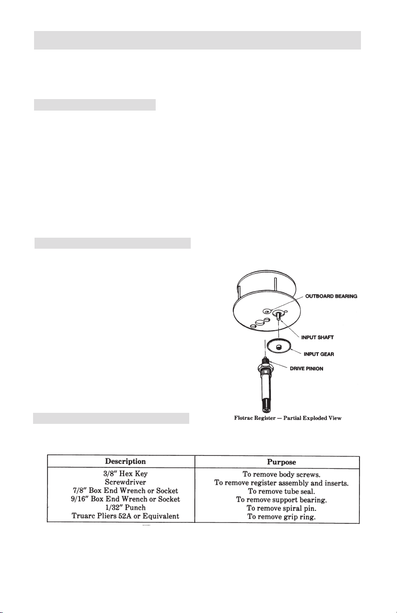
Lubrication
The input shaft, outboard bearing and pinion should be lubricated at least twice
a year.
A. Input Shaft
Lubricate with several drops of No. 10
motor oil or equivalent.
B. Outboard Bearing
The oil impregnated bronze bearing
requires no additional lubrication.
C. Pinion
Add standard weight grease on pinion
teeth and mating gear.
Tools Required
The following tools are required to perform calibration and maintenance adjust-
ments on the Model 306:

6
Troubleshooting
If trouble develops, the procedures listed in Table below will usually locate the
problem and suggest a solution. Normally, problems will be restricted to the
rotor assembly, magnetic drive coupling or register assembly.
Calibration
The Model 306 Flotrac Meter was calibrated at the factory using clean water. If
subsequent proving shows a change in the calibration constant, the meter can be
corrected by changing the calibration gears.
The required correction is determined by comparing the True Volume of
uid passing through the meter during a proving procedure with the Metered
Volume shown on the register. The required correction is:
The new pinion and input gears should be selected so that the percent change
in gear ratio is as nearly equal to the correction as possible. This may be accom-
plished with the aid of U.S. Barrel Registers Table on page 7 or Liters/Cubic
Meters Registers Table on page 8).
Example:
Gear Combination................... Pinion - 18T,Input - 75T
True Volume ........................... 100 Bbl
Metered Volume...................... 104 Bbl
The required correction is:

7
Using "US Barrels" Table below, move along the vertical axis (at P/I combina-
tion) to 18/75. As shown, selection of a new pinion input gear combination
with a 17-tooth pinion gear and a 74-tooth input gear will result in a -4.28
correction. The new metered volume will therefore be 104 x (1-0.0428) =
99.55 gallons for a residual error of (100 -99.55)/100 or -0.45%, which is
within specication.
The "Liters/Cubic Meters" Table on the next page is used in the same way to
correct meters which have metric registers.
Part numbers of the various pinion and input gear assemblies are provided in
Part Number Table at the top of page 9.

8

9
Gear Part Numbers
Repair
Repairs are readily made on the meter, either in-line or on the bench. Remem-
ber that all threads are right-handed, and that parts should be installed in reverse
order of removal. In addition, 0-rings should be inspected prior to reassembly,
and replaced if cuts or swelling are evident.
To protect the register, it should be removed by unscrewing two cover screws,
lifting off the case, register and gasket.
Repairs to the faceplate are limited to replacing the glass if it is broken. This
requires the installation of a new retaining ring, since the ring breaks when
removed.
Removal and installation procedures for major components are covered in the
following paragraphs:
A. Rotor Replacement
1. To remove rotor - Remove six body screws with 3/8" hex key, lift off
meter cover (with its O-ring in place), then slip old rotor off journal tube
noting direction of rotor blades.
2. To install rotor - Place rotor on journal tube with at side of blades
facing uid now, as noted during disassembly, slide cover with its 0-ring
and rotor into body cavity with dowel pin aligned with cover. The 0-ring
should t into its groove without pinching and the body cap screws
evenly tightened.
B. Journal Tube Replacement
1. To remove tube assembly - If the meter is in its normal position,
with the register up, the tube can be removed without taking the cover
off. Taking the 7/8" wrench, unscrew the tube without bending the
exposed shaft. The tube can then be lifted out of the cover, leaving
the rotor in the meter. The slight resistance that is felt is supplied by
the 0-ring.
If the meter is not in the normal position, the tube should be removed
after taking the cover off, since the rotor will not remain centered after
the tube is withdrawn.

10
B. Journal Tube Replacement (continued)
2. To install the tube assembly - Align the rotor with the tube, insert
the tube into the cover with care not to pinch the O-ring as it slides into
place, and tighten the tube with the wrench.
NOTE: The cover register cavity must be dry at all times.
C. Input Gear and Pinion Replacement
1. To remove the input gear and pinion - First remove the journal
tube assembly as instructed in the preceeding section. With a 1/32”
punch, drive the pinion spiral pin from the shaft assembly and remove
the pinion. With a small screwdriver, loosen the input gear set screws
and remove the input gear from the input gear shaft.
NOTE: For the proper combinations of input gear and pinion, refer to
Gear Selection Tables on pages 7 and 8.
2. To install the input gear and pinion - Reinstallation is accom-
plished by reversing the procedure described in the preceeding para-
graph.
D. Output Shaft Bearing Replacement
1 . To remove shaft assembly - After removing the register, use a
9/16" socket or box end wrench to unscrew the bearing support
assembly (including the shaft), driven magnet and output pinion. To
remove the shaft from the assembly it is necessary to push out the
small pin in the pinion with a 1/32" punch, supporting the shaft so
it will not be bent. After sliding pinion off, remove the shaft from the
bearing support. If required, the magnet can be taken off by using
Truarc Pliers, No. 52A, to take the grip ring off the shaft.
2. To install the shaft assembly - The bearing support and its bearings
are replaced as a unit, the shaft inserted with the magnet at the end
opposite the wrench hexagon, the pinion is placed with its pin hole
aligned with that of the shaft, and the pin installed with care again
not to bend shaft. The assembly, with 0-ring in place, should then be
inserted into the journal tube and tightened.
E. Insert Replacement
1. To remove inserts - Remove the meter cover, slip off the rotor,
unscrew two screws in each insert (note porting orientation), and lift
out. Calcium carbonate deposits will make this difcult if the water is
not treated. Each insert has a thrust washer that can be removed with
light force. These washers can be reversed to present a new surface to
the rotor, or replaced-if worn.
2. To install inserts - Place each insert with its washer in the proper
housing with porting oriented properly. Fasten with the at head
screws below the insert surface. Reassemble the rotor, cover, body
O-ring, and fasten down as before.
F. Register
If register is damaged, replacement of complete register is recommended.
11
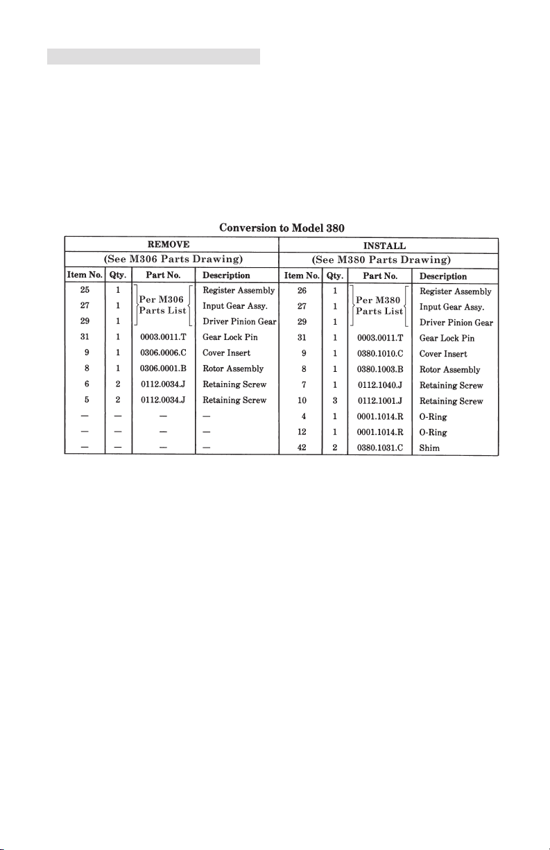
Conversion to Model 380
The Model 306 Flotrac Meter (capacity 9-90 gpm) can be converted to a Model
380 Flow Meter (capacity 1.5-15 gpm) by replacing the parts noted in the
Table below. When making this conversion, refer to M306 and M380 Parts
Drawings and Parts Lists in Section 5 (starting on page 14). Replace worn parts
as necessary (refer to Repair Procedure starting on page 9).
WARNING
REMOVE ALL LINE PRESSURE FROM THE METER
BEFORE REMOVING THE METER COVER CAP SCREWS.

12
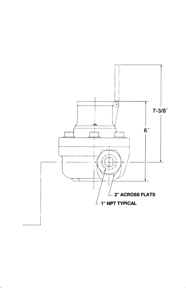
SECTION 4 - INSTALL/DIMENSIONAL DRAWINGS
Model 306
Note: Measurements are in inches.
13
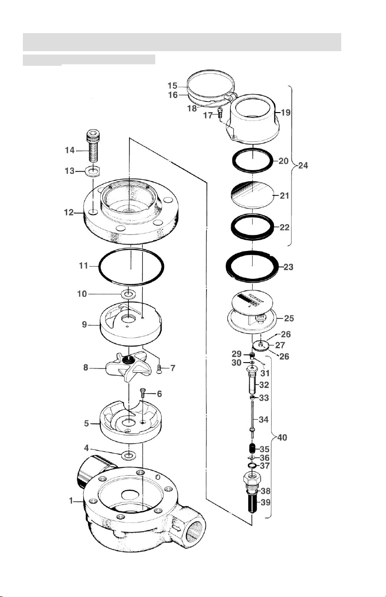
14
306 Parts Drawing
SECTION 5 - PARTS DRAWING/LIST
15
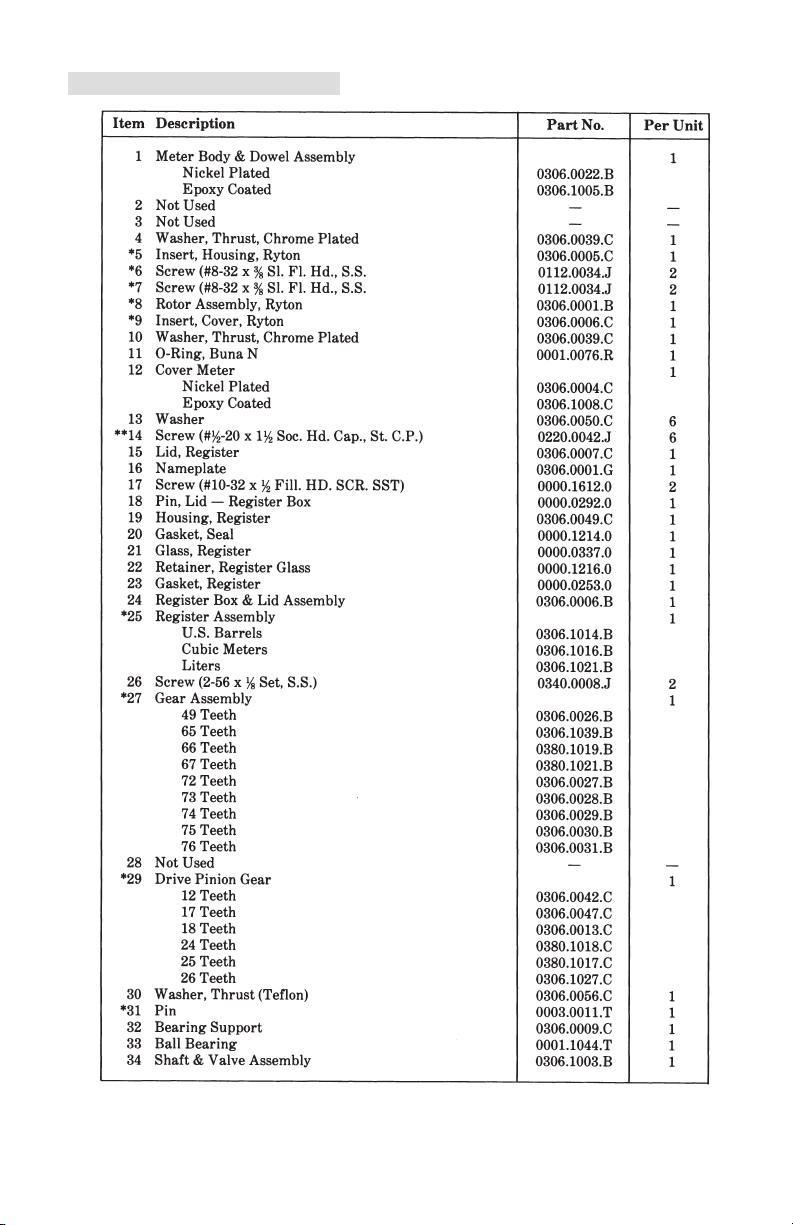
306 Parts List

16
306 Parts List (continued)
SECTION 6 - PARTS DRAWING/LIST (continued)

17
380 Parts Drawing

18
380 Parts List
SECTION 6 - PARTS DRAWING/LIST (continued)

19
M380 Parts List (continued)

Product Warranty
A. Warranty
Cameron International Corporation ("Cameron") warrants that at the time of shipment, the
products manufactured by Cameron and sold hereunder will be free from defects in mate-
rial and workmanship, and will conform to the specications furnished by or approved by
Cameron.
B. Warranty Adjustment
(1) If any defect within this warranty appears, Buyer shall notify Cameron immediately.
(2) Cameron agrees to repair or furnish a replacement for, but not install, any product
which within one (1) year from the date of shipment by Cameron shall, upon test and
examination by Cameron, prove defective within the above warranty.
(3) No product will be accepted for return or replacement without the written authoriza-
tion of Cameron. Upon such authorization, and in accordance with instructions by
Cameron, the product will be returned shipping charges prepaid by Buyer. Replace-
ments made under this warranty will be shipped prepaid.
C. Exclusions from Warranty
(1) THE FOREGOING WARRANTY IS IN LIEU OF AND EXCLUDES ALL OTHER EX-
PRESSED OR IMPLIED WARRANTIES OF MERCHANTABILITY, OR FITNESS FOR
A PARTICULAR PURPOSE, OR OTHERWISE.
(2) Components manufactured by any supplier other than Cameron shall bear only the war-
ranty made by the manufacturer of that product, and Cameron assumes no responsibility
for the performance or reliability of the unit as a whole.
(3) "In no event shall Cameron be liable for indirect, incidental, or consequential damages
nor shall the liability of Cameron arising in connection with any products sold hereunder
(whether such liability arises from a claim based on contract, warranty, tort, or otherwise)
exceed the actual amount paid by Buyer to Cameron for the products delivered hereunder."
(4) The warranty does not extend to any product manufactured by Cameron which has been
subjected to misuse, neglect, accident, improper installation or to use in violation of instruc-
tions furnished by Cameron.
(5) The warranty does not extend to or apply to any unit which has been repaired or altered
at any place other than at Cameron's factory or service locations by persons not expressly
approved by Cameron.
Product Brand
Barton® is a registered trademark of Cameron International Corporation ("Cameron").
Sensia LLC
200 Westlake Park Blvd
Houston, TX 77079
+1-866-773-6742
sensiaglobal.com
Table of contents
Other Sensia Measuring Instrument manuals

Sensia
Sensia TA-1000 Plus Instructions for use

Sensia
Sensia NUFLO MC-III User manual

Sensia
Sensia NuFlo Scanner 2000 Instructions for use

Sensia
Sensia CamCor User manual

Sensia
Sensia LEFM 2010FE User manual

Sensia
Sensia NuFlo User manual

Sensia
Sensia Barton 7000 Series User manual

Sensia
Sensia CamCor CT Series Instructions for use

Sensia
Sensia CALDON LEFM CheckPlus-C User manual

Sensia
Sensia CALDON SVM 289Ci User manual


