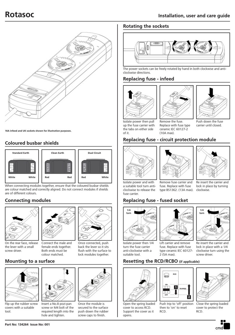
Ilsco SpecPRO CRM 26 Series User manual

PO Box 15732 Brooksville, FL 34604-5732- Phone: 888-987-8877/850-654-5559, Fax 850-654-3844 –www.surgesuppression.com
2018 SSI®. Rev Date 10/30/2018
Page 1of 2
Doc # SS06274
Description:
Parallel connected, AC power Surge Protective Device.
Application:
Designed for use at ANSI/IEEE location categories C, B and A.
Designed to protect all types of loads fed from individual
disconnects, sub-panels, distribution panels and service entrance
locations.
Warranty:
10 Years
Unit Listings:
Listed to ANSI/UL 1449 by UL (E315947), CSA (MC#241804);
UL1283
Circuit Design:
Parallel connected, hybrid circuit design incorporating both
component level thermal fusing and internal over-current fusing. All
protection circuits are encapsulated in our high dielectric compound
to promote long component life and protection from the weather and
vibration. Includes additional filtering circuitry to reduce and/or
eliminate the effects of both internal and external ringing transients.
Directly Connected
Protection Modes:
L-N, (Normal Mode), and N-G (Common Mode).
(Based on Wye configuration, L-G on Delta configuration.)
Input Frequency:
50-60 Hz (60 Hz typical)
EMI/RFI Filtering:
Up to 52 db normal mode, 49 db common mode
Circuit Diagnostics:
Super Bright LED, 1 per phase, normally on. See pg. 2 for additional
diagnostics options
Connection/mounting:
#10 Wire (pre-installed), hub (pre-installed on base models, installed
at the time of installation on optional enclosures) and integral, multi-
point mounting feet.
Circuit Interrupt:
Internal component level thermal fusing and patented circuit board
mounted, over-current fusing. No external over-current protection
required. (Note: National and local codes may require the use of a
circuit interrupt device(s) if conduit is added to make the wired
connection to the panel or gear). SCCR = 200 kA
Nominal Discharge
Current (In) Rating:
10 kA (CRMA26); 20 kA** (CRMB26) (**Complies with the requirements
of UL 96A Master Label for Installation Requirements for Lightning Protection
Systems)
Designed for mission critical applications, the CRM series is a great choice for most
small electrical panel applications. The CRM series of Surge Protective Devices
provides the features, performance and value required by discriminating specifying
engineers. This device is intended for protection of general-purpose load
applications ranging from individual equipment disconnects and sub panels to
distribution panels and service entrance locations. It is extremely effective in limiting
lightning surges as well as internally generated transients.
The CRM series provides an effective blend of leading edge suppression design
technology, straight forward, no frills engineering and customer driven, value added
options. Specify the CRM with confidence.
Key Features:
Industry Leading Measured
Limiting Voltage Performance
Independent Verification of
Performance and Safety
Component Level Thermal
Fusing
Patented Internal Over-current
Fusing
Circuit Encapsulation
10 Year Warranty
Voltage
Code
ANSI/UL 1449 (Fourth Edition)
Voltage Protection Rating (VPR)
L-N
HL-N
L-G
HL-G
N-G
L-L
HL-L
1P1
600
-
1500
-
700
-
-
1S1
600
-
1500
-
700
1200
-
3Y1
600
-
1500
-
700
1200
-
3D1
600
1200
1500
2000
700
1200
1800
3Y2
1200
-
2500
-
1200
2500
-
3N2
-
-
1200
-
-
2500
-
3N4
-
-
1800
-
-
4000
-
CRMx26 Series
260 kA Per Phase
Peak Surge Current
ANSI/UL1449 UL
A = Type 2 SPD 10 kA
B = Type 2 SPD 20 kA

Page 2of 2
Doc # SS06274
MEASURED LIMITING VOLTAGE PERFORMANCE AND ELECTRICAL SPECIFICATIONS
Voltage
Code
Circuit Type
Peak Surge
Current (Amps)
Per Mode
&
Per Phase
MCOV
Mode
ANSI/IEEE C62.41 & C62.45
6” External Lead Length Let-Through Voltage Test Results
Cat A
30 Ω 100 kHz Ring Wave
2 kV / 67 A @ 270° Phase Angle
Category C (High) 10 kA
8/20 Current Driven Test†
1P1
120 V, Single Ø
(2 wire + ground)
260,000
150
150
L-N
N-G
52 V
67 V
729 V
991 V
1S1
120/240 V, Split Ø
(3 wire + ground)
260,000
150
150
L-N
N-G
52 V
67 V
729 V
991 V
3Y1
120/208 V, 3ØY
(4 wire + ground)
260,000
150
150
L-N
N-G
52 V
67 V
729 V
991 V
3D1
120/240 V, 3Ø
(4 wire + ground)
260,000
150
320
150
L-N
HL-N
N-G
52 V
40 V
67 V
729 V
1,374 V
991 V
3Y2
277/480 V, 3ØY
(4 wire + ground)
260,000
320
320
L-N
N-G
40 V
53 V
1,374 V
1,661 V
3N2
240 V, 3
(3 wire + ground)
260,000
320
L-G
1,038 V
1,414 V
3N4
480 V, 3
(3 wire + ground)
260,000
550
L-G
1,559 V
2,071 V
Measured Limiting Voltage (MLV) Test Parameters: Positive polarity, Category A: Line power applied, Category C: No line power applied, Voltages are peak (±10%). Measured Limiting Voltages are
measured from the insertion point on the sine wave to the peak of the surge for powered tests. Each MLV is the average of the phases within that mode of protection. In order to duplicate the results, the
specified mode of protection must be tested in all phases (except N-G) and averaged together. (Individual mode or shot results may vary by more than 10%. Scope Settings: Time Base = 10 microseconds
per division, Sampling Rate = 2.5 Gigasamples/sec, Bandwidth = 400 MHz (200 MHz for Cat C), Probes: Tektronix P5100/P6015A. These settings help to assure MLV results are accurate). All tests
performed with 6” lead length (external to the enclosure), simulating actual installed performance. The MLVs reported above are certified by Third-Party, Independent Testing. Individual test
reports are available upon request.
†The MLV reported for the Category C High, 10 kA 8/20 Current Driven Test is determined by measuring the MLV of one of the fifteen 10 kA impulses impressed through the SPD during the Nominal
Discharge Current (In) Test from C62.62TM-2010 and ANSI/UL 1449 (4th Edition). This is not the MLV recorded during the pre- and/or post-test 6 kV / 3 kA Combination Wave Test used to determine the
VPR of the SPD. The VPRs are reported on page 1 of this specification.
Model Number Example: CRMB263Y2D3
Base Model:
SPD Rating:
PSC
Voltage Code:
Options:
CRM
A = Type 2 SPD 10 kA C = Type 1 SPD 10 kA
B = Type 2 SPD 20 kA D = Type 1 SPD 20 kA
26 (260 kA)
See Voltage Codes
3Y2
See Option codes
D3
Integral
Disconnect
D5, D6 option
configuration
(Enclosure
24x20x10)
(CSA)
SPD
Inside
Options
Description
AC10
Basic Internal Audible Alarm
AC11
Advanced Internal Audible Alarm
w/ on, off, and test
AC10S6
Basic Alarm/ Surge Counter
AC11S6
Advanced Alarm w/ surge
counter on, off, and test
D5 (CSA)
Integral Disconnect Switch **
D6 (CSA)
Integral Disconnect Switch (no
external handle) **
E1
Hub on right side of enclosure
N
Removes N-G Tracking Circuit
P
Flush Mount Plate
R2
Remote LED's in separate
enclosure
S
Internal Surge Counter
W
NEMA 4 Metal Enclosure
X
NEMA 4X (Box-in-box) with
terminals
XS
NEMA 4X Stainless Steel
Corrosion Resistant Enclosure
Additional options may be available upon
request.
** Housed in a NEMA 4X Composite Enclosure
Enclosure Dimensions
Inches
(mm)
Standard
Model
Enclosure Options
W
X
A
14.00
(356)
14.00
(356)
18.00
(458)
B
12.00
(305)
12.00
(305)
16.00
(407)
C
6.00
(153)
6.00
(153)
10.00
(254)
D
15.50
(394)
15.50
(394)
19.50
(496)
E
15.98
(406)
15.98
(406)
19.98
(508)
F
13.23
(309)
13.23
(309)
17.23
(411)
G
14.75
(375)
14.75
(375)
18.94
(482)
H
10.00
(254)
10.00
(254)
14.00
(356)
Type
NEMA
12
Steel
NEMA
4
Steel
NEMA
4X
Composite
lbs.
(kg)
14
(6.36)
14
(6.36)
32
(14.52)

© 2017 Surge Suppression, LLC NN00142 Rev. Date: 09/19/2017
WARNING - HAZARDOUS VOLTAGES ARE PRESENT. Improper installation may result in serious injury to the installer and/or damage to the
electrical system or related equipment. Read all instructions before beginning the installation. Safety equipment must be used as prescribed by OSHA,
whenever working around hazardous voltages.
Failure of unit and/or consequential equipment damage due to improper installation or misapplication is not covered by the product
warranty.
Voltage measurements and installation must be completed by a licensed/qualified electrician in accordance with the National and/or Canadian
Electric Code, State, and Local codes. These requirements supersede this instruction.
POWER MUST BE REMOVED FROM THE ELECTRICAL SYSTEM BEFORE INSTALLING THE UNIT.
INSTALLATION MATERIALS REQUIRED
The following is a list of materials that may be needed for proper installation of this Surge Protective Device (SPD). This list is intended to help the installer anticipate
materials needed for a successful installation. The installer should become familiar with the scope of work to avoid lost time and improper installation. Failure to use fittings
that are “Listed”will void the “Listing” of the SPD.
For Splices: 3 (or more) cable taps; such as: NSI IPCS- 2001 or 7501 (per Code).
Attachment Hardware: Use (four) screws or anchor toggle bolts, flat washers and lock washers.
¾” hub (included with most models).
Tools: Drill & bits, Mechanical Knock out Set, Channel Locks™, Level, Screwdrivers, Appropriate Safety Equipment.
WIRING DIAGRAM
This device is suitable for use on a circuit capable of delivering not more than 200,000 RMS symmetrical
Amperes, for the respective models’ (max.) nominal voltage shown in the Table of Maximum Suggested
Operating Voltages on page 2.
The SPD is equipped with integral fuses. This allows the device to be installed directly to the system bus
bars, to the main lugs in a panel or disconnect, or to a circuit breaker. Consult NEC/CEC, State and
Local Codes to assure compliance†.
In the event that one or more of the LED status indicators fail to illuminate, the entire device should be
returned for warranty replacement. If service of the device is a consideration (i.e: removal and
replacement), and there is no means to remove power from the SPD without removing power from the
entire system, the installer may consider incorporating a disconnect device between the SPD and the
system connecting point.
The design of these units provides superior protection for sensitive/critical equipment connected to
distribution panels, sub-distribution panels or individual equipment disconnects. These units are
designed for use at IEEE C62.41 Location Categories A, B, and C. “Voltage Responsive” type units are
designed to be used in 50 to 420 Hz applications. NOTE: SPDs with model numbers beginning with the
letter “C” are “Frequency Responsive” (sine wave tracking) units and are designed to be used in 50 to 60
Hz applications only and shall not be used at locations where the voltage frequency fluctuates (i.e.: on
the output of variable frequency drives).
When inspecting the panel prior to installation, insure that a proper safety ground is present as required
by the NEC/CEC.
Note: Pre-existing breakers of the rated load size (30 amp, etc.), that are serving existing loads, may be
utilized if the breaker is “Listed” for this application (see NEC) and provided the owner/tenant has
authorized multiple conductor termination.
†[ex.: NEC ‘10-foot tap rule’ for direct bus tapping.].
3 Phase Delta
No Neutral
System
SPD
INSTALLATION DIAGRAM
PHASEA
PHASE B
PHASE C
GROUND
INTERNALLY
FUSED
NOTE FOR ISOLATED GROUND
If the electrical system uses an isolated ground, connect the SPD ground to the isolated ground bus. EXCEPTION FOR METAL ENCLOSURES AND/OR METALLIC
HUBS –For metal enclosures and/or metallic hubs, the SPD ground wire is bonded to the enclosure internally. If the system uses an isolated ground, the SPD enclosure
must be isolated from the panel or load it is being connected to through the use of an insulated conduit fitting or other “Listed” fitting. In this installation, the ground wire
from the SPD must terminate at the isolated ground bus.
BEFORE INSTALLATION
For proper performance, the SPD must be installed with the shortest lead length possible. Sharp bends should be avoided.
No position-oriented components are used in the units. Devices can be mounted upside down or sideways allowing for shortest possible lead lengths.
There are a few basic principles for surge suppression installation. They are:
1. For proper performance, the SPD must be installed with the wires as short and straight as humanly possible. Any sharp bend in the wire is unacceptable!
This applies to phase, neutral, and ground leads. The objective is to reduce the lengths of wire provided on each unit, not add to it. The priority is to the
phase leads, then the neutral, and then the ground lead.
2. Install the SPD on the side of the panel closest to the neutral bus, if present, and use a breaker on the same side.
3. Use a breaker close to the neutral bus and the SPD to keep the wires as short and straight as humanly possible.
4. The ground wire may be connected to the panel by using a ground lug installed near the SPD in the can or frame as they are grounded. (See exception
above for Isolated Grounds).
Installation Instruction for
Three Phase Delta, 4-wire
Suppressors with Internal Fusing
(three phases and ground)
PO Box 15732
Brooksville, FL 34604
Phone (888) 987-8877
Fax (352) 799-6987
info@surgesuppression.com

© 2017 Surge Suppression, LLC NN00142 Rev. Date: 09/19/2017
Table of Maximum Suggested Operating Voltages and Model Wire Colors
3-Phase
DELTA
Nominal
System Voltage
3Nx Model
Voltage Code
Phase
To
Phase
Phase
To
Ground
Phase A
Wire
Color
Phase B
Wire
Color
Phase C
Wire
Color
Ground
Wire
Color
120
3N1
132 V
132 V
Black
Black
Black
Green
240
3N2
264 V
264 V
Black
Black
Black
Green
380
3N3
418 V
418 V
Black
Black
Black
Green
480
3N4
528 V
528 V
Black
Black
Black
Green
600
3N6
660 V
660 V
Black
Black
Black
Green
690
3N7
759 V
759 V
Black
Black
Black
Green
INSTALLATION STEPS (NOTE: 3N6 and 3N7 Models must be connected in A, B, C Phase rotational sequence to the electrical system.)
STEP 1: Check Voltages
Confirm that the nominal system voltage does not exceed the maximum suggested operating voltage for the model to be installed according to the Table above. All
voltage measurements should be completed with a RMS voltmeter. DO NOT INSTALL THE FUSED UNIT IF THE MEASURED VOLTAGE EXCEEDS THE
MAXIMUM SUGGESTED OPERATING VOLTAGE OF THE DEVICE.
CAUTION: Do not proceed further until power has been removed from the electrical system.
STEP 2: Mounting the Unit
Non-lug type SPDs are provided with 18-24 inches of #10 AWG/TEW stranded wire. For best performance, mount the SPD so that all wires can be cut and connected in
the shortest, straightest path possible, the goal being 6 inches of wire length or less. For every inch of conductor longer than 6-inches, you increase the let-through voltage
of the SPD by 21.7 volts for an ANSI/IEEE Category B, 6kV, 3kA impulse.
No sharp bends should be made in the installation. If bends are unavoidable, make them smooth and flowing. The device contains no position-dependent
components; therefore, the device can be mounted upside down or sideways.
Do not cut any wires until suppressor has been mounted. Units with plastic hubs must be installed with the non-metallic flexible conduit and extra hub.
While holding the SPD on the wall, determine the shortest, straightest distance between the hub on suppressor and hub to be installed on panel. Cut the flexible
conduit to shortest length possible to fit securely over both hubs.
Twist the trimmed flexible conduit onto the extra hub. Slide conduit and hub over wires of the SPD and twist the conduit onto the hub of the SPD.
Connect the extra hub to the panel and mount the SPD to the wall.
STEP 3: Connecting “Optional Form C” Dry Relay Contacts (Applies only to SPDs with optional Dry Relay Contacts)
Make sure power is removed from surge suppressor.
Open surge suppressor lid and note encapsulant height prior to drilling or punching enclosure. (Allow internal clearance for locknuts).
Drill 0.5” diameter clearance hole through side, top or bottom of unit and install a watertight strain relief (i.e.: Altech #225-A00 (Part No. SR011).
NOTE: Surge suppressor is equipped with two sets of contacts. The first set (labeled 1 & 2, N/C) is normally closed and the other set (labeled 3 & 4, N/O) is
normally open with power applied.
Contacts are rated at 60 W (from 30 VDC @ 2 A to 150 VDC @ 0.4 A) or 100 VA (from 50 VAC @ 2 A to 220 VAC @ 0.45 A).
Alarm contacts accept AWG #26 (0.14mm2) to AWG #16 (1.5mm2) wire. Wire size must be in compliance with NEC/CEC, State or Local codes for power on circuit.
Follow rules for the class of wiring used when routing alarm leads. To maintain NEMA-4 (IP66) rating use appropriate cable and watertight strain relief.
Connect alarm circuit(s) to Normally Open (N/O) or Normally Closed (N/C) terminals as required.
Upon replacing front cover of suppressor, certain models allow various lid rotations (90° to 180°) for improved label orientation. (model specific)
STEP 4: Wire the SPD into the Electrical System
Carefully lay out the wires keeping them as short and straight as possible. (Wires may be slow-twisted together thereby reducing RF-impedance.) After a satisfactory
layout has been made to the appropriate termination points as described below, cut the wires and connect them as instructed.
Connect the GREEN ground wire from the SPD to the system ground bus bar or to a lug mounted in the can or frame close to the SPD if the Ground bus bar is not
close following the current NEC/CEC. Refer to earlier sections for systems utilizing an isolated ground.
Connect the phase wires or “hot” wires (see table above for wire colors) from the SPD to the phase conductors or buses of the electrical system through the required
circuit interrupts (fuses or breakers) described above. Note that the SPD has internal fusing and does not require external circuit interrupts (external fuses or
breakers). The Phase conductors may be directly connected to the phase conductors or buses after the main disconnect.
Upon replacing front cover of suppressor, certain models allow various lid rotations (90° or 180°) for improved label orientation (< model specific).
Before energizing, measure the voltage again to ensure it is within the levels in the table above.
Immediate failure of the SPD will occur if installed on voltages higher than shown in the Table at the top of this page.
STEP 5: Apply Power to the Surge Suppressor
The LED indicators should be illuminated. If not, remove power from the SPD and contact Surge Suppression, LLC at: 1-(888)-987-8877.

© 2018 Surge Suppression, LLC
Page | 1 Doc # SS05788
PO Box 15732
Brooksville, FL 34601
Phone 888-987-8877
Fax 850-654-3844
TEN YEAR LIMITED WARRANTY –SpecPRO™ FOUR MODE PRODUCTS
Surge Suppression, LLC warrants for a period of ten (10) years from date of retail purchase
that if its product ceases to properly function as a direct result of any electrical anomaly,
including lightning, Surge Suppression, LLC will repair or replace the product without charge,
subject to the terms and conditions set forth herein. If, in the sole subjective opinion of Surge
Suppression, LLC the product has been modified, altered, tampered with, misused or
misapplied or repaired by any entity other than Surge Suppression, LLC, or subjected to
abuse, the warranty is void. The warranty shall not apply unless the product is installed by a
qualified licensed and/or bonded electrician. The warranty period for repaired or replacement
products shall be only the remaining portion of the original limited warranty. Any defect
appearing more than ten (10) years from the date of delivery to purchaser, shall be deemed to
be due to ordinary wear and tear. Surge Suppression, LLC, however, assumes no risk or
liability resulting from the use of its products, including but without limiting the generality of the
foregoing: (1) The use of this product in combination with any electrical or electronic
components, circuits, systems, assemblies or any other materials or substances; (2) The
improper application or unsuitability of this product for use in any circuit or assembly. All
warranty inspections and parts must be obtained at Surge Suppression, LLC. The giving of, or
failure to give, any advice or recommendations by Surge Suppression, LLC shall not constitute
any warranty by or impose any liability upon Surge Suppression, LLC. THIS WARRANTY
DOES NOT GUARANTEE UNINTERRUPTED ELECTRIC SERVICE. REPAIR OR
REPLACEMENT OF THIS PRODUCT IS THE EXCLUSIVE REMEDY OF THE RETAIL END
USER PURCHASER. THIS WARRANTY IS IN LIEU OF ALL OTHER WARRANTIES,
EXPRESS OR IMPLIED, INCLUDING, BUT NOT LIMITED TO, ANY IMPLIED WARRANTY OF
MERCHANTABILITY OR WARRANTY OF FITNESS FOR A PARTICULAR USE OR
PURPOSE; ALL OF WHICH ARE HEREBY EXCLUDED AND EXPRESSLY DISCLAIMED.
SURGE SUPPRESSION, LLC SHALL IN NO EVENT BE LIABLE FOR ANY SPECIAL,
INDIRECT, INCIDENTAL, PUNITIVE, OR CONSEQUENTIAL DAMAGES OF ANY KIND OR
CHARACTER, INCLUDING, WITHOUT LIMITATION, THE EXPENSE OF INSTALLATION OR
REMOVAL OF THIS PRODUCT, LOSS OF REVENUE OR PROFITS, FAILURE TO REALIZE
SAVINGS OR OTHER BENEFITS, LOSS OF COMPUTERIZED OR OTHER DATA, DAMAGE
TO ANY ELECTRIC OR ELECTRICAL EQUIPMENT, INCONVENIENCE AND/OR FOR THIRD
PARTY CLAIMS MADE AGAINST THE WHOLESALE OR RETAIL PURCHASER OF THIS
PRODUCT, EVEN IF BEFORE OR AFTER PURCHASE SURGE SUPPRESSION, LLC HAS
BEEN ADVISED OF THE POSSIBILITY OF SUCH DAMAGES. SURGE SUPPRESSION,
LLC’S TOTAL LIABILITY FOR ANY CLAIM MADE AGAINST IT SHALL IN NO EVENT
EXCEED THE PURCHASE PRICE PAID TO SURGE SUPPRESSION, LLC FOR THE
DEFECTIVE PRODUCT. As a condition precedent to SURGE SUPPRESSION, LLC’s
performance pursuant to this Warranty, Purchaser must return this product within the Warranty
period FOB SURGE SUPPRESSION, LLC’s place of business in Brooksville, Florida. Please
call 888-987-8877 for warranty return procedures. Return authorization is required.
Table of contents
Other Ilsco Power Distribution Unit manuals
Ilsco
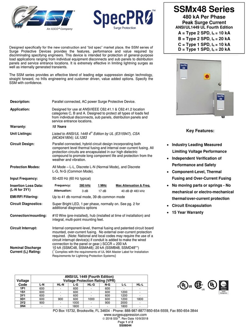
Ilsco SSI SpecPro SSM 48 Series User manual
Ilsco
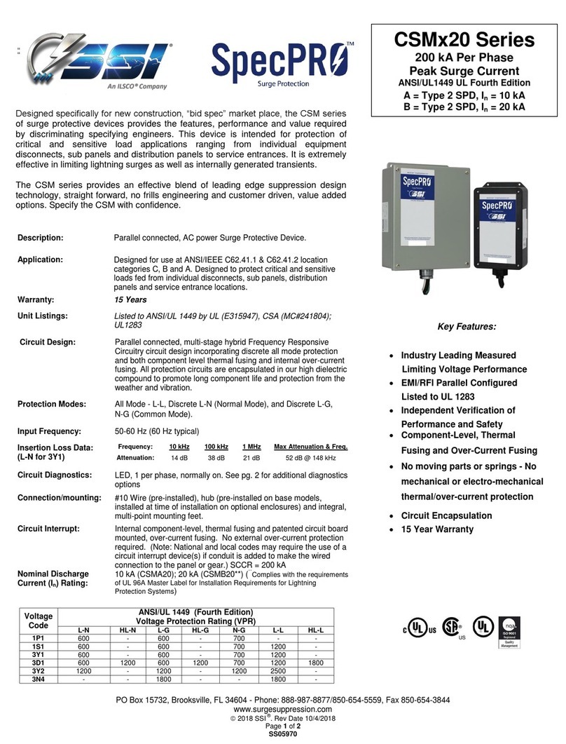
Ilsco SSI SpecPRO CSM 20 Series User manual

Ilsco
Ilsco SSI SpecPRO CSM 36 Series User manual
Ilsco
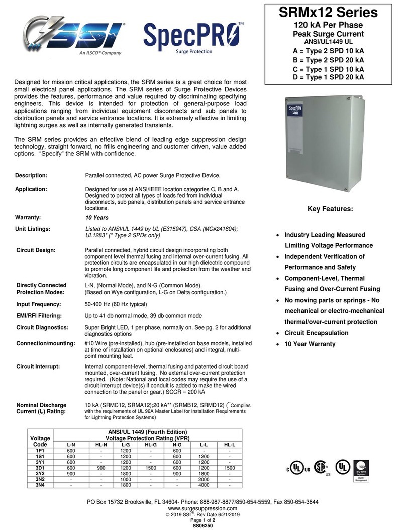
Ilsco SSI SpecPRO SRM Series User manual
Ilsco
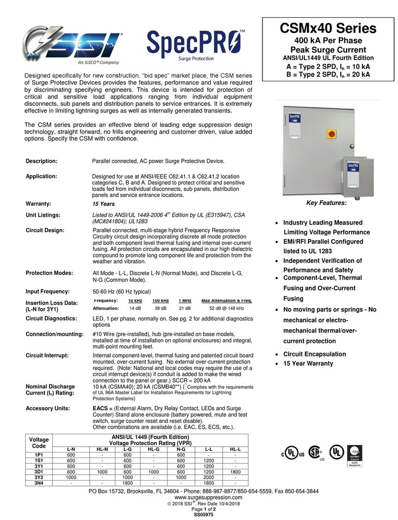
Ilsco SSI CSM 40 Series User manual

Ilsco
Ilsco SSI SpecPRO SRM 14 Series User manual
Ilsco
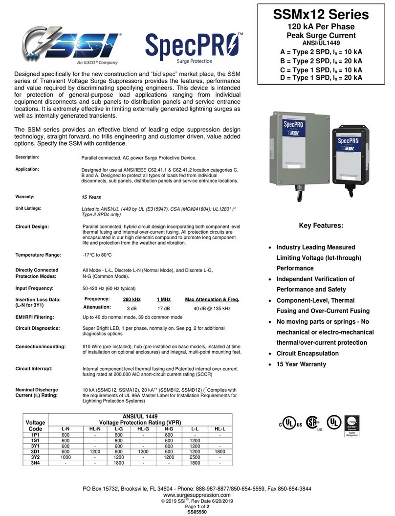
Ilsco SSI SpecPRO SSM 12 Series User manual
Popular Power Distribution Unit manuals by other brands
BASE Electronics
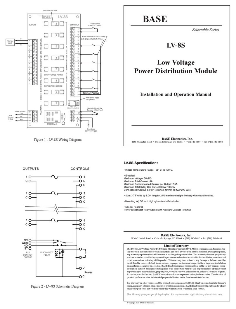
BASE Electronics LV-8S Installation and operation manual
Belkin
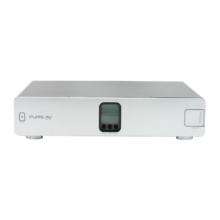
Belkin PureAV Power Console PF60 user manual
Compaq
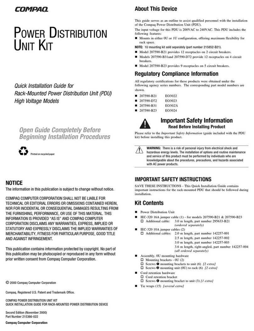
Compaq 207590-B21 - Power Distribution Unit Strip Quick install guide
ABB
ABB Relion 630 Series Operation manual
Inter-m
Inter-m PD-6359A Operation manual
Siemens
Siemens SIPROTEC 5 V8.83 manual
