BONKOTE PATRIOT MW50 User manual
MW50
LA type soldering iron controller
Instruction manual(QSS-4000)
Date prepared: March 2019
The 6
th
edition
JAPAN BONKOTE CO., LTD.
PATRIOT

Contents
1 Preface·················································································································· ··1
2 Notesforsafety··········································································································1
3 RecommendationofAuto-tuningbeforeuse····································································1
4 Notesforinstallationanduse····················································································· ··2
5 HowtouseMW50Controller
(A)Contents···············································································································3
(B)Nameofthebody···································································································3
(C)Howtoassemble ·································································································4
(D)Howtouse ···········································································································5
6 Optionalsetting
(A)Alarmfunctionupperlimitsetting ·············································································8
(B)Alarmfunctionlowerlimitsetting···············································································8
(C)Temperaturerecoveryspeedsetting·········································································9
(D)Upperlimitsettingofsettingtemperature···································································9
(E)Monitorindicationofoperationoutputamount·····························································9
(F)Lockfunction······································································································10
(G)Anti-resetwindupsetting·····················································································10
(H)Auto-PowerDown/Auto-PowerOffsetting·······························································11
(I)PIDvaluemanualsetting·······················································································13
(J)DeviceNumbersetting·························································································15
7 CharacterList··········································································································16
8 Howtomaintenance ································································································17
9 Standardspecifications·····························································································17
10 GuaranteeandAfter-sales serviceofMW50
(A)Troubleshootings································································································18
(B)Guarantee ·········································································································18
(C)Aftersalesservice·······························································································18

1
1. Preface
Thank you very much for purchasing [MW50 Controller].
Please read Notes for safety before use, and use this machine properly, keep this
manual after read.
2. Notes for safety
CAUTION!
Be sure to read this manual before using this machine.
・ Never touch the power and 5P core relay cord with dump hands. Otherwise, you may get hurt due to electric
shockandetc.(deathatworse)
・ Never dampen the iron tip with water or other liquid. Otherwise, burst cord may cause fire, malfunction, electric
shockandetc.(deathatworse)
・ Take great care to handle the soldering iron while it is not rested on the workbench. Otherwise the heated tip
maycause fireor adjacentoperatorsmay gethurt.
・ Nevertouch theiron tipwhilecurrentisbeingpassed. Otherwise, youmaygetburnt. If you haveto touch the
tip like replacement of irontipor parts, turn off the power and pull out the power plug from the receptacle, wait for
awhileandcheckifithasalreadycooleddownsufficientlybyusingathermometer oretc.
・ Do not overhaul the machine when the machine has trouble. Otherwise, it may cause malfunction, electric
shock and etc (death at worst). Contact with our customer service department and follow instructions to make
maintenance.
・ Be sure to use proper replacement parts such as fuse, checking capabilities. Otherwise, parts with wrong
capacitiesmaycausefire,malfunctionandetc.
3. Recommendation of Auto-tuning before use
It is recommendable to do Auto-tuning before use, to operate with good effect for each conditions (iron tip
temperature, shape of iron tip, etc.) and each environment, although each parameter is set with the standard
parametervalueattheshipment.
※Auto-tuning withsimplekeyoperation.(How touse,please referP.7)
!

2
4. Notes for installation and use
・ Thismachine isdesignedwithearthspecification. Forsafety, besuretouse anearth-quippedreceptacle.
(Ifyoudonothavesuchreceptacle,installanearthseparately.)
・ Forsurrounding conditions,usethismachineona neat workbench onwhichaconductive matis put.
・ Refrain from place where the machine would be exposed too much moisture, direct sunshine, much dust and
vibration.
・ Inorderto preventstatic electricity, it isrecommended usingastaticelectricityremovaldevice,wriststrapetc.
・ Odoris generatedduetothe useof solder andflux. Besuretoventilate workplaces.
(E.g.fittingofventilatoretc.)
・ Besureto pull outthepowerplug,whenthemachineisnotused.
・ Besureto grab thepowerpluginsteadofcable, wheninserting andpulling outtheplug.
・ If the power voltage is changedfrom 100V to 220V, make sureof confirm the specifications of the soldering iron
unitbefore the change.
・ Ifflammableobjects areplaced nearthismachine, thereisa danger offire. Becareful.
・ Besureto check theslackofeachscrewbeforeuse. Ifthescrewis loosen,tightit.
・ Donotusethismachine for purpose other than theoriginalpurpose.
3
5. How to use MW50 controller
(A) Contents
※100V with 3PCHI-plug cable, 220V with 3EPV-plug cablewill be attached.
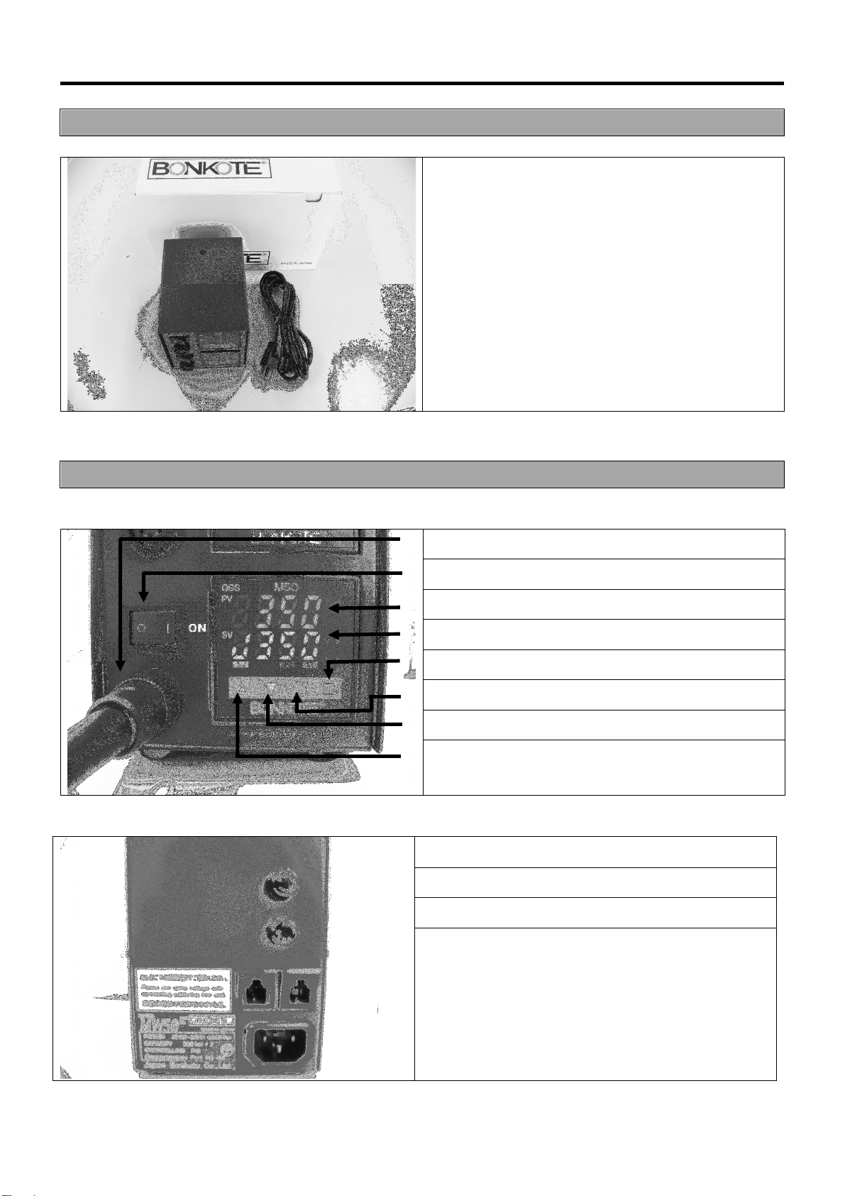
(B) Name of the body
《 Front 》
①
5PConnector
②
Power switch
③
PV display(Working temperature)
④
SV display(Setting temperature)
⑤ □
key(Speed setting)
⑥
key(Function key)
⑦ ▽
key(Setting value Down key)
⑧ △
key(Setting value Up key)
《 Back 》
⑨3P inlet
⑩Fuse holder (2pcs)
⑪Modular jack (2pcs)
①MW50 Controller
②3P Power Cable
①
②
⑨
⑩
⑪
4
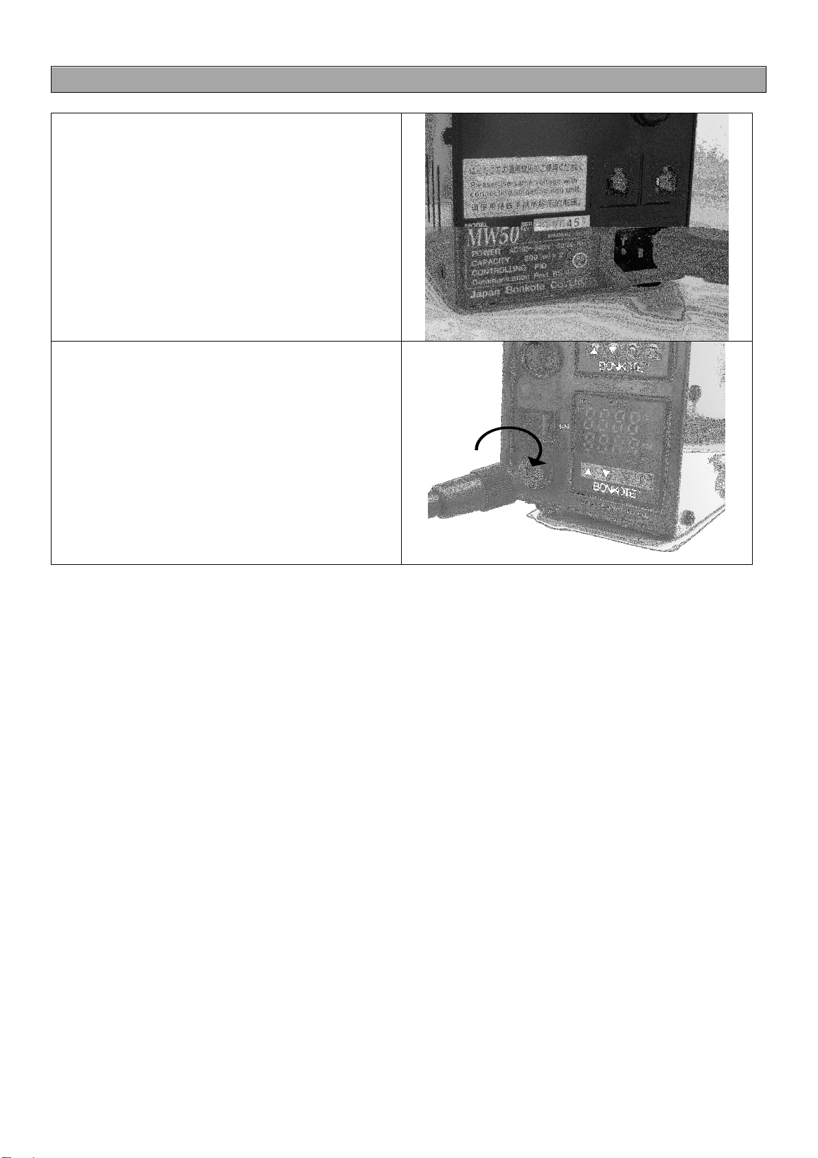
(C) How to assemble
①
Insertthe Power cable into 3Pinlet.
②
Connect the soldering iron to 5P connector
at the front, and lock it with rotating to right.
Please make sure the voltage of the
soldering iron unit is applicable to the
input-voltageof MW50controller.

5
(D) How to use
① Turn on Power
Insert the power plug intothe receptacle and confirm the input voltage of soldering iron and theone of
this controller are same, then set the power switch to ON.
※Ifuse100Vtypeof soldering ironwith220input voltageinoversea, itmakes heaterdamaged.
②Setting and confirmation of the sensor input type
MW50 controller is workable for 2 different kinds of soldering iron units, one is J-sensor type and other
K-sensor type. Please make sure that the each sensor-type of soldering iron unit and the one of
controller should bethesame. Otherwise, temperature control isunabletowork.
※The sensor type is set at the shipment.
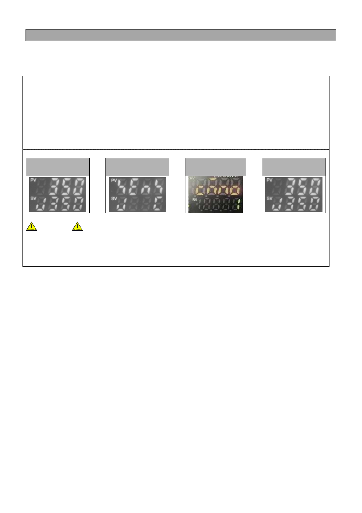
~How to confirm the sensor type~
A: Controller
Atthe operation mode,
or
is indicated at left side of SV screen.
ControllingwithJ typeindicates
. ControllingwithKtype indicates
.
Pleasecheck thesensortypeofthecontrollerissamewith theoneof connecting solderingiron unit.
《Jtype》 《Ktype》
B: Soldering iron unit
LAsoldering ironunithas 2differentkinds of sensortype,J type andK type
Please checkthelabel ofthesolderingironunit.
Letter J printed after the model number is J type, no letter printed after the model number is
Ktype.
Ktypesoldering ironunit
Jtypesoldering ironunit
あ
6
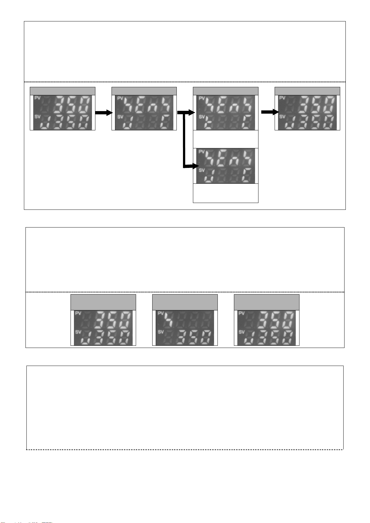
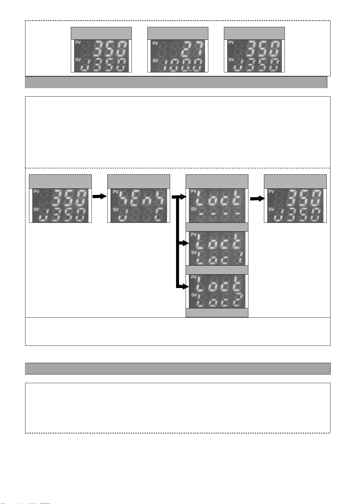
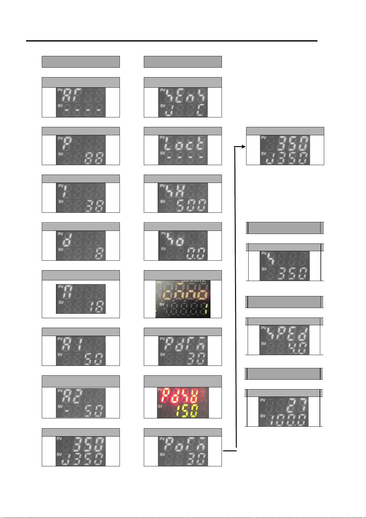
~How to set the sensor type and temperature indication~
Ⅰ:Attheoperationmode,press
key approx. 3 seconds with pressing ▽key.
is indicated at PVscreen.
Ⅱ:Inputsuitable sensortypeby △or ▽key, and push
key8 timestoreturnto operationmode.
Operation mode
⇒
Sensortypeinputscreen
⇒
Selectsensortype
⇒
Operation mode
・Control with K type
・Indication in (℃)
・Control with J type
・Indication in (℃)
③ Set the temperature
Initial setting : 350℃ Setting range : 0~500℃
Ⅰ:Attheoperationmode,press
keyonceand
is indicated at PV screen.
Ⅱ:Setthetemperatureby △or ▽ key.
Ⅲ:Press
keyonceto return tooperation mode.
Operation mode
⇒
Settingtemperature
settingscreen
⇒
Operation mode
④ Compensation of temperature differences
Initial setting: 0℃ Setting range:-100.0℃ ~ 100.0℃
Ⅰ:Attheoperationmode,press
key approx. 3 seconds with pressing ▽key.
isindicatedatPVscreen.
Ⅱ:Push
key3 times and
is indicatedatPV screen.
Ⅲ:Inputthecompensate value by △or ▽key at SVscreen.
Ⅳ:Afterinput thevalue,push
key5 timestoreturntooperationmode.

7
Operation mode
⇒
Sensortypeinput
screen
⇒
Temperature
compensation
screen
⇒
Operation mode
How to calculate the compensation value by Standard measurement instrument
Example:
Temperatureinstruments indicates: 350℃ Controller indicates: 355℃
Setthecompensation valueas -5
Thecompensation value=Standard measurement instrument indication-Controller indication
⇒350-355=-5
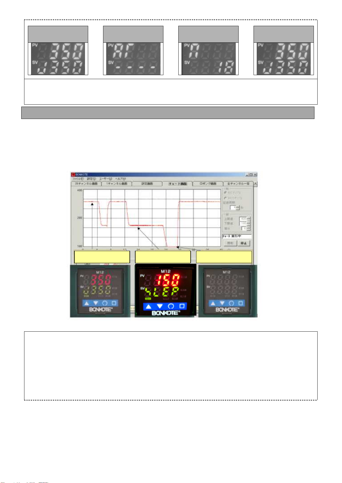
⑤ StartAuto-tuning after reach to setting temperature
Ⅰ:Attheoperationmode,push
keywithpressing △key,
is indicatedat PV screen.
Ⅱ:Push △key oncein order toindicate
atSVscreenaswell.
Ⅲ:Push
keyto startAuto-tuning. (ATblinkingstarts at rightbottom ofthescreen)
Auto-tuningis doneabout 2minuites(ATstopsat right bottomofthe)
Operation mode
⇒
ATsetting screen
⇒
ATsetting screen
⇒
Operation mode
あ
Auto-tuning: Itautomatically calculate suitable PIDvaluewhichcontrolsoldering iron.
Please make sure to do Auto-tuning otherwise, soldering iron may not perform with enough effect.
Attention
PleasemakesuretodoAuto-tuning after reach to setting temperature.
Please do not touch the soldering iron during Auto-tuning (during AT is blinking at right bottom of
the screen). PID value is automatically calculated by fluctuating
temperature (about 2minutes).
Touching the soldering iron during the fluctuation in temperature, it cause incorrect PID value
calculation and soldering iron may not perform with enough effect.
Auto-tuningis done when the blinkingstops.
Above ④、⑤ areunnecessarytodoeverytime. Pleasedoitwhenchangeirontipand changesettingtemperature.
※At shipment,Auto-tuning is not done yet. Please make sure to doAuto-tuning before use.

8
6. Optional setting
MW50 has various functions. Please use the function with your convenience.
(A)Alarm function Upper limit setting
① Set the upper limit alarm of soldering temperature
Initial setting: 50℃
Ⅰ:Attheoperationmode,press
keywithpressing △ key.
is indicatedatPV screen.
Ⅱ:Push
key5 times,
isindicated at PV screen.
Ⅲ:Input thevalueby △or ▽keyatSVscreen. Push
key2timestoreturnto operationmode.
Operation mode
⇒
AT setting screen
⇒
Upper limit alarm function
⇒
Operation mode
あ
Upper limit alarm: It alarms when the temperature exceed the range ○○℃ of settingtemperature.
Example:
Theupperlimitissetas50. setting temperature is 350℃.
Italarmswhen temperature becomeover 400℃.
Set 0 whenalarmfunction is unnecessary.
(B)Alarm function Lower limit setting
① Set the lower limit alarm of soldering temperature
Initial setting:-50℃
Ⅰ:Attheoperationmode,press
keywithpressing △ key.
is indicatedatPV screen.
Ⅱ:Push
key6 times,
isindicated at PV screen.
Ⅲ:Inputthevalueby △▽ keyat SVscreen. Push
keyonceto returntooperationmode.
Operation mode
⇒
AT Setting Screen
⇒
lower limit alarm function
⇒
Operation mode
あ
Lower limit alarm: It alarms when the temperature exceed the range ○○℃ of settingtemperature.
Example:
Thelowerlimitis setas -50. settingtemperature is 350℃.
Italarmswhen temperature becomeunder 300℃.
Set 0 whenalarmfunction is unnecessary.

9
(C) Speed Setting
① Control the recovery speed to setting temperature
Initial setting:4.0 Setting range:1.0 ~ 10.0
Ⅰ:Attheoperationmode,push □keyonce.
isindicated atPVscreen.
Ⅱ:Inputsuitable value by △or ▽keyat SV screen.
Ⅲ:Afterinput thevalue,push □key onceto returntooperationmode.
Operation mode
⇒
Speedsettingscreen
⇒
Operation mode
Set 1.0: Recovery speed isfast, and overshooting becomelarge.
Set10.0: Recoveryspeedisslowly, and overshooting become less.
(D) Upper limit of setting temperature
① Set the upper limit of setting temperature
Initial setting:500℃ Setting range:0 ~500℃
Ⅰ:Attheoperationmode,press
keywithpressing ▽key about3 seconds.
isindicatedatSVscreen.
Ⅱ:Push
keytwice.
isindicatedat SV screen.
Ⅲ:Inputthevalueby △or ▽key at SVscreen,push
key6 timestoreturntooperationmode.
Operation mode
⇒
Inputtypesettingscreen
⇒
Upper limit setting
temperature setting screen
⇒
Operation mode
(E) Monitor indication of operation output amount
① Monitoring operation output amount of heater
Ⅰ:Attheoperationmode,press
keyabout3 seconds.
Operation output amount(0~100%) is indicated atSV screen.
Ⅱ:Push
keyto returntooperationmode.
10
Operation mode
⇒
operationoutputamount
screen
⇒
Operation mode
① Lock setting value prevention from error setting
Initial setting:Non-lock
Ⅰ At the operation mode, press
keywithpressing ▽ key about3 seconds.
isindicatedatPVscreen.
Ⅱ Push
keyonce,
is indicated at PVscreen.
Ⅲ Select thetypeof lock by △or ▽key, push
key7 timestoreturn tooperationmode.
Operation mode
⇒
Inputtypesetting
screen
⇒
Lock selection screen
⇒
Operation mode
Non-lock
Lock1
Lock2
: Non lock
: Lockup all function-setting exceptlockfunction.
: Lockup all function-setting exceptlockand temperature function.
(G)Anti-reset wind-up setting
① Control Overshooting
Initial setting:18% Setting range:0 ~ 100%
Ⅰ:Attheoperationmode,push
keywithpressing △key.
is indicated at PV screen.
Ⅱ:Push
key4 times,
is indicated at PV screen.
Ⅲ:Afterinput thevalueby △▽ keyat SV screen, push
key3 timestoreturnto operationmode.
(F) Lock function
11
Operation mode
⇒
AT Setting screen
⇒
Anti-reset wind-up
setting screen
⇒
Operation mode
It is recommendable NOT to change the initial setting value. Setting lower value could restrain from
overshooting, however,there ispossibility unableto recovertothesetting temperature.
(1)Setting of parameter value
Prevent from Deterioration and Oxidization of the iron tip, the soldering iron tip temperature is lowered
(Power Down) and supplying electric power to the heater is stopped (Power Off) automatically when
theirontip temperatureis no changed during the specified time(available tosetthe time).
Thisfunctionis alsoeffectivefor savingenergy andsafety.
① Setting ofAuto-Power Down time
Initial setting :30 minutes Setting range:0 ~ 120 minutes
Ⅰ At the operation mode, press
keywithpressing ▽key about3 seconds toindicate
on PV screen.
Ⅱ Push
key5 timestoindicate
on PVscreen.
Ⅲ Set thevalue by △or ▽key, push
key3 timestoreturntooperationmode.
(H)Auto-Power Down/Auto-Power Off setting
Power Down
Power Off
Operation mode
12
Operation mode
⇒
Input type setting
screen
⇒
Auto-Power down time
setting screen
⇒
Operation mode
AboutAuto-Power Down time:
e.g.:setvalue30minutes
No fluctuation in the temperature of iron tip during stand-by mode for more than 30 minutes, the
decline intemperaturewill startautomatically.
Duringtheprocess“
”andthesetting value ofAuto-Power Downwillbeindicated alternately.
Set the value “0” if you want to cancel this mode.
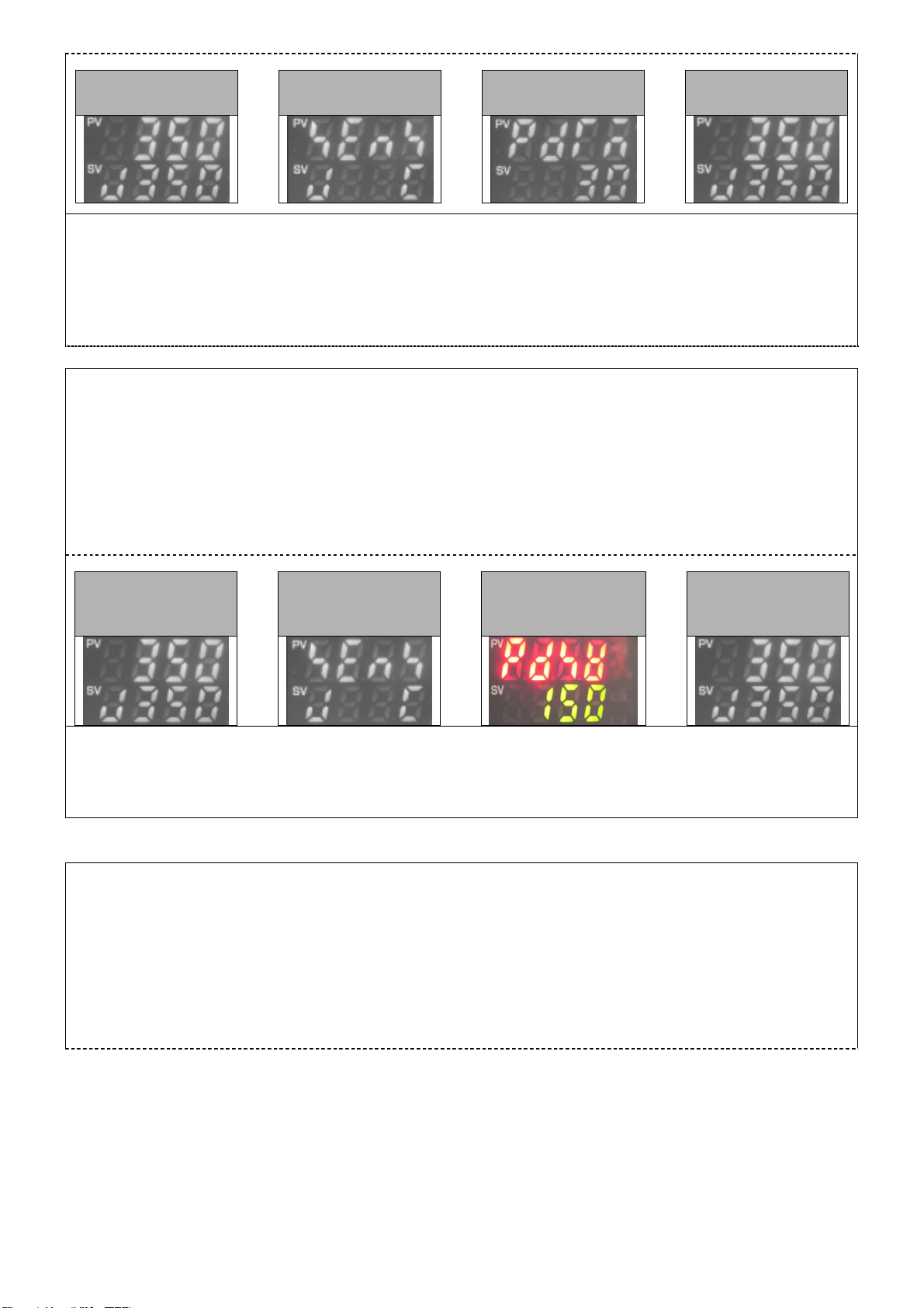
② Setting ofAuto-Power Down temperature
Initial setting:150℃ Setting range:0~ Setting temperature-1℃
Ⅰ At the operation mode, press
keywithpressing ▽key about3seconds.
isindicatedatPVscreen.
Ⅱ Push
key6 timestoindicate
is indicated at PV screen.
Ⅲ Input thevalueby △or ▽key, push
key3 timesto return tooperationmode.
Operation mode
⇒
Input type setting
screen
⇒
Auto-Power down
temperature setting
screen
⇒
Operation mode
Auto-PowerDown temperature isthe temperatureduringAuto-Power Down procedure.
Example:
WhensetAuto-Power Downtemperatureto「150℃」,controller willstandby with「150℃」.
Settingtemperature inoperation is350℃Itonlycan setto lowerthan349℃.
③ Setting ofAuto-Power Off time
Initial setting:30 minutes Setting range:0 ~ 120 minutes
Ⅰ At the operation mode, press
keywithpressing ▽key about3secondstoindicate
on PV screen.
Ⅱ Push
key7 timestoindicate
on PVscreen.
Ⅲ Set thevalue by △or ▽key, push
keyonce toreturn tooperationmode.
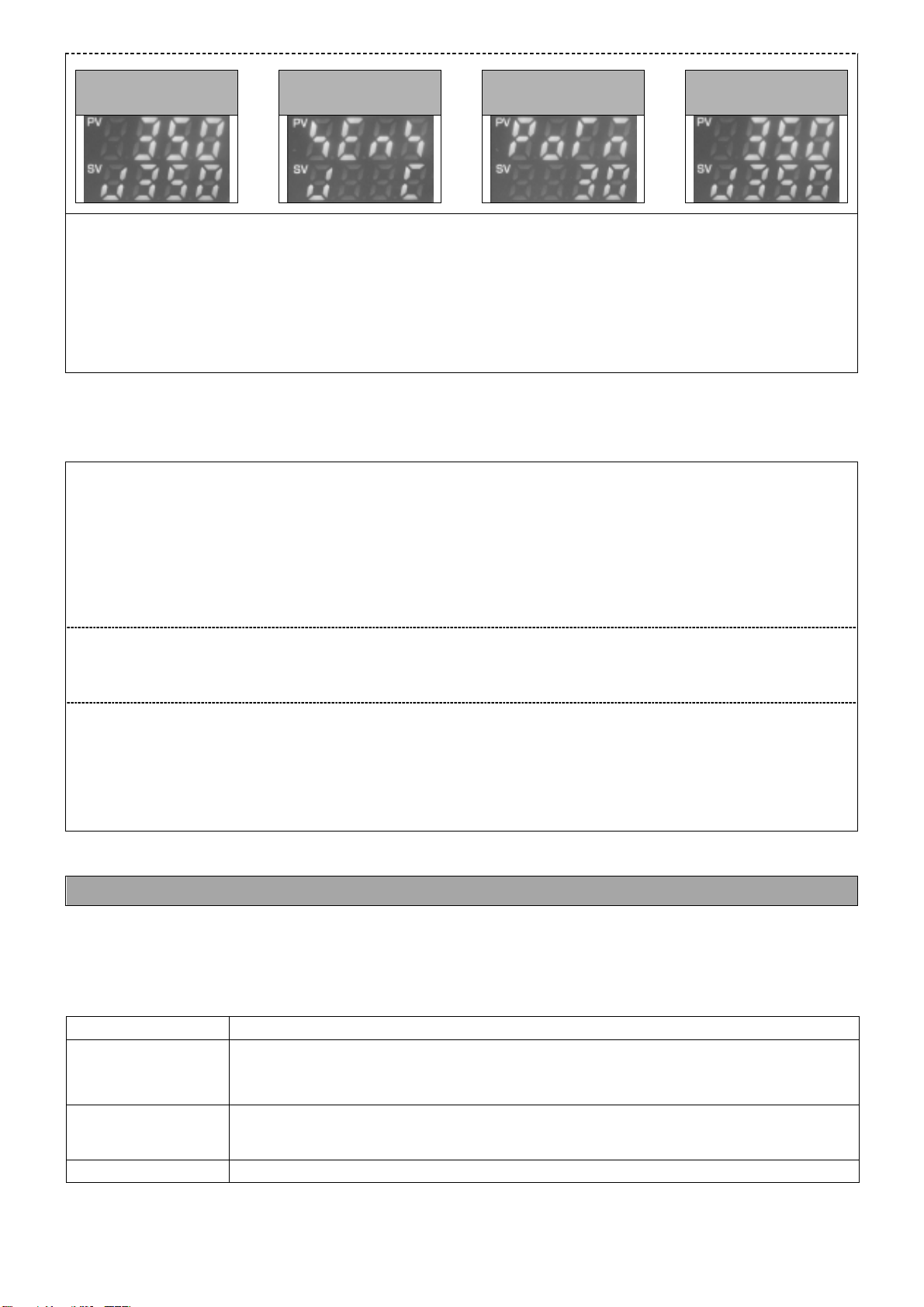
13
Operation mode
⇒
Input type setting
screen
⇒
Auto-Power down time
range setting screen
⇒
Operation mode
AboutAuto-Power Off time:
e.g.:Settingvalue 「30 minutes」
During Auto-Power Down operation (
is blinking at SV value), no fluctuation within the
temperature range while「30 minutes」, the controller recognizes that soldering iron is not using, and
automaticallyturn offthe power.
OnceAuto-Power Off operation starts,it becomes same condition with Power off.
Set the value “0” if you want to cancel this mode.
(2) Other operation method
① Return to operation mode fromAuto-Power Down mode
Ⅰ:When the temperature move outfrom the Auto-Power Down temperature range(initial value: 5℃),
Auto-Power Down function is released, and return to operation mode. For example clean iron tip
bymoisturizedspongeis easytoreturn.
When Auto-Power Down function is not released, press △or ▽key more than 3seconds to
release.
Ⅱ:AtAuto-PowerDownmode,press △ or ▽keymorethan3secondstoreturntooperationmode.
② Return to operation mode fromAuto-Power Off mode
Ⅰ:Turn onthe power again.
③ Manual operation
Ⅰ:At the operation mode, after reach to setting temperature, press △ or ▽key more than 3
secondstomovetoAuto-Power Downmode.
Ⅱ:AtAuto-PowerDownmode,press △ or ▽keymorethan3secondstoreturntooperationmode.
(I) PID value manual setting
Thismachine is basicallyunnecessarytodo PIDsettingdue toloadingAuto-tuningfunction. It isable to
domanualsettingifovershootingwhichsolderingirontiptemperaturebecome highoccurredwithspecial
work. Please use PIDmanual setting withyourconvenience.
Major effect
P
Proportional
band
Overshoot become less with bigger value however, temperature recovery time
become longerandtemperature drops during soldering maybelarger.
I
integration time
Overshoot become less with bigger value however, temperature recovery time
become longerandtemperature drops during soldering maybelarger.
D Overshoot become less with smaller value however, temperature recovery time

14
derivative time
becomelonger. Thisvaluewillbeset or adjustedafter PvalueandIvalue isset.
① Setting of Proportional band
Initial setting:88℃ Setting range:0 ~ 1000℃
Ⅰ:Attheoperationmode,push
keywithpressing △key.
isindicatedat PVscreen.
Ⅱ:Push
keyonce,
isindicatedatPV screen.
Ⅲ:Inputthevalueby △or ▽key,push
key6 timesto return tooperationmode.
Operation mode
⇒
AT setting screen
⇒
Proportional band
setting screen
⇒
Operation mode
あ
② Setting of Integration time
Initial setting:38seconds Setting range:0 ~ 1000℃
Ⅰ:Attheoperationmode,push
keywithpressing △key.
isindicatedat PVscreen.
Ⅱ:Push
key2 times,
is indicated at PV screen.
Ⅲ:Inputthevalueby △▽ key, push
key5 timestoreturntooperationmode.
Operation mode
⇒
AT setting screen
⇒
Integration time
setting screen
⇒
Operation mode
あ
③ Setting of Derivative time
Initial setting: 8 seconds Setting range: 0 ~ 300℃
Ⅰ:Attheoperationmode,push
keywithpressing △key.
isindicatedat PVscreen.
Ⅱ:Push
key3 times,
is indicated at PV screen.
Ⅲ:Inputthevalueby △▽ key, push
key4 timestoreturntooperationmode.
Operation mode
⇒
AT setting screen
⇒
Derivative time setting
screen
⇒
Operation mode
あ
15
(J) Device Number Setting
(1) Device Number Setting is required under the condition of QSS-4000 Concentrated temperature
management System forsoldering iron.
①Setting of Device Number
Initial Setting: 1 Setting Range: 1 ~ 95
: At the operation mode, push
△
key with pressing key in 3 seconds, is indicated at
PVscreen
:Pushkey 4 times, isindicatedatPVscreen.
: Input Device Number by △▽ keyon the SV screen, thenpushkey 6times toreturn to
operationmode.
Operation mode
⇒
Input type setting
screen
⇒
Device No. setting
screen
⇒
Operation mode
Attention
Thenumbering muststartwith“1”
e.g. The firstconnectedM50’sdevice number mustbe“
1
” ,and 2nd one is“2”andcontinued
16
7.Character list
Allcharactersetting of M50 listed.
△key +
key ▽key +
key
↓
↓
Auto-tuning
Inputtype setting
↓
↓
Proportionalbandsetting
Lockfunction selection
Operation mode
↓
↓
↓
Integration timesetting
Uppertemperaturesetting
↓
↓
Derivative timesetting
Compensatetemperature
↓
↓
Anti-reset wind-upsetting
Devise number setting
↓
↓
Upperlimitalarmsetting
Auto-PowerDowntimesetting
↓
↓
Lowerlimitalarmsetting
Auto-Power Downtemperature
setting
↓
↓
Operation mode
Auto-Power Off time setting
□key
↓
Settingtemperaturechange
Key press
↓
Operationamountoutput
key
↓
Settingtemperaturechange
17
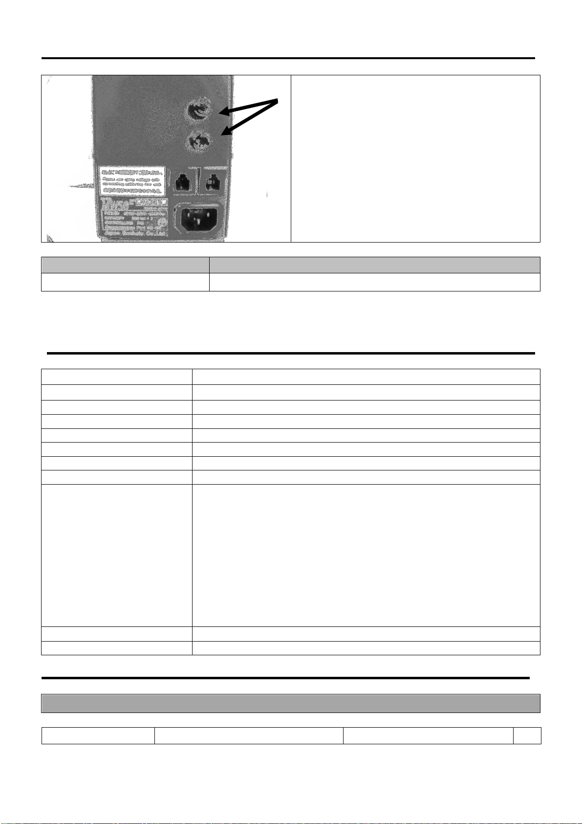
8. How to maintenance
①Loosen the fuse holder and remove it
.
Check the fuse if need change, and
replace to a new fuse.
Model No. Specification
Fuse 3A Glass fuse 250V 3A(φ5.2×20mm)
9. Standard specification
Inputvoltage AC100~240V
Temperaturerange 0~500℃(At shipment)
Powercode 100V:3PCHI 220V:3EPV
Dimension 97(W)×73(H)×130(D)mm
Weight Lessthan750kg
Fuse 3A
Temperaturecontrolmethod PIDcontrol(Auto-tuningsetting)
Temperatureindication PV:LED(red), SV:LED(green)
Errorindication
“ ̄ ̄ ̄ ̄” Over scale :Temperature exceed upper limitation of
indicatable temperature
※Error of sensor
(indication)
“____” Under scale :Temperature exceed lower limitation of
indicatable temperature
※Oppositepoleof sensor
(indication)
Material(case) Steel
Power consumption Less than 10VA(Controller only)
(A) Trouble shooting
Condition Cause Measures Pag
10. Guarantee and After sales service of MW50

18
e
Soldering iron does not
heat. 1. Unableto power on
①The power cable/switch are set
correctly? Check the power cable and the
switch 4
②Isthefuseblown? Replacetoa new fuse 17
2. Soldering iron is not heated although
poweron
①Is the soldering iron and the controller
completelyconnected? Check theconnecting
②Is the soldering iron tip sensor
completely connected to the soldering
iron?
Check how to replace soldering iron
tip
③Istheheaterelementconsumed? Check theconduction and replace to
newheater element
Temperatureunstable ①IsAuto-tuning done? Set upAuto-tuningfunction 7
②Temperature does not reach to setting
temperature SetupAnti-reset windfunction 10
③Over-shooting islarge
Keyoperation isunable
①Isthelockfunctioneffective? CheckthesettingofLockfunction 10
(B) Guarantee
Our products are shipped after sever factory tests and inspections. However, if you find
malfunctions or defects due to problems in workmanship or transportation, please contact your
dealersorus. Theguaranteeperiod of yourproducts is inoneyearafteryourpurchase,except
for replacement parts
.
(C)After sales service
Whenyouthink the product doesnot operateproperly, read thismanual againtocheck.
Ifstilltroubles are notsolved, pleasecontactwithyourdealeror us.
JAPAN BONKOTE CO., LTD.
600-14Kasahara,Mito,Ibaraki 310-0852 JAPAN
TEL: +81 29-241-2725
FAX:+8129-241-2726
http://bonkote.co.jp
E-mail :info@bonkote.co.jp
Table of contents
Other BONKOTE Controllers manuals


