BONKOTE PATRIOT User manual

M12
LA type soldering iron controller
Instruction manual
Date prepared: April 2018
The 9th edition
JAPAN BONKOTE CO., LTD.
PATRIOT

Contents page
1Preface············································································································1
2Notes for safety ································································································1
3Auto Tuning before use ·····················································································1
4Notes for installation and use ············································································2
5How to use M12 controller
(A)Contents ·································································································3
(B)Name of the body ·····················································································3
(C)How to assemble ······················································································4
(D)How to use ······························································································5
6Optional function
(A)Alarm function upper limit setting ·····························································7
(B)Alarm function lower limit setting······························································8
(C)Temperature recovery speed setting ···························································8
(D)Upper limit setting of set temperature························································8
(E)Indication of manipulated output value ······················································9
(F)Lock function···························································································9
(G)Anti reset wind up setting··································································· 10
(H)Auto Power Down / Auto Power Off setting ··············································10
(I)PID value manual setting ······································································13
7List of character ····························································································15
8How to maintenance······················································································16
9Standard specification····················································································16
10 Guarantee and After sales service
(A)Trouble shooting ···················································································17
(B)Guarantee····························································································17
(C)After sales service ·················································································17

1
1. Preface
Thank you very much for purchasing M12 CONTROLLER.
Please read this Notes for safety before use, and use this machine properly.
After read this manual, please keep it.
2. Notes for safety
Be sure to read this manual before using this machine.
Never touch the power cord and the soldering iron with dump hands.
Otherwise, you may get hurt due to electric shock and etc. (death at worse)
Never dampen the iron tip with water or other liquid. Otherwise, burst cord
may cause fire, malfunction, electric shock and etc. (death at worse)
Take great care to handle the soldering iron while it is not rested on the
workbench. Otherwise, the heated tip may cause fire or adjacent operations
may get hurt.
Unplug the iron unit and allow sufficient time for it to cool when replacement
or maintenance.
Do not overhaul the machine when the machine has trouble. Otherwise, it may
cause malfunction, electric shock and etc. (death at worse) Contact our
customer service department and follow instructions to make maintenance.
Be sure to use proper replacement parts such as fuse, checking capabilities.
Otherwise, parts with wrong capacities may cause fire, malfunction and tec.
3. Auto Tuning before use
We would recommend Auto Tuning before use, although each parameter is set in
the standard value at the shipment. By doing so, soldering irons will perform with
good effect according to iron tip temperature, shape of iron tip, working
environments and so on.
※This function will be set automatically by keypad. (Please refer to P.7)
!
CAUTION

2
4. Notes for installation and use
This machine is designed with earth specification. Make sure to use an earth
equipped receptacle. If you do not have such receptacle, install an earth
separately.
Use this machine on a neat bench on which a conducive mat is put.
Do not place where the machine would be exposed too much moisture, direct
sunshine, much dust and vibration.
In order to prevent static electricity, we recommend that you use a static
electricity removal device, wrist strap etc.
Odor is generated due to the use of solder and flux. Be sure to ventilate work
places. e.g. Install a ventilation fan etc.
Be sure to pull out the power plug when the machine is not used.
Be sure to grab the power plug instead of the cord, when plugging and
unplugging.
When change power voltage from 100V to 220V for example, make sure to
confirm the specifications of the soldering iron before use.
Please keep flammable objects away from this machine.
Be sure to check the slack of each screw and tighten them securely before use
this machine.
Do not use this machine for purpose other than the original purpose.
3
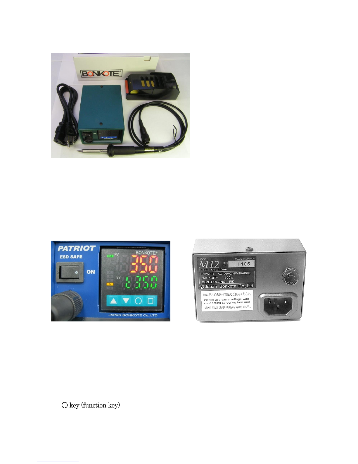
5. How to use
5-A:Contents of soldering station set
①3P Power cord ※
②M12 Controller
③BON-11 Iron stand
④TB-170J Soldering iron
NOTE:
This picture is M12-TB-170J station set.
※3PCHI plug cord for 100V, or 3EPV plug
cord for 220V comes with a controller.
5-B:Name of the body
《FRONT 》《BACK 》
①Power switch ⑨Fuse holder
②5 pin connector ⑩3 pin inlet
③PV display (working temperature)
④SV display (setting temperature)
⑤△key (value up)
⑥▽key (value down)
⑦
⑧□key (speed setting)
②
③
④
①
⑤
⑥
⑧
⑦
⑨
⑩
①
②
③
④
4
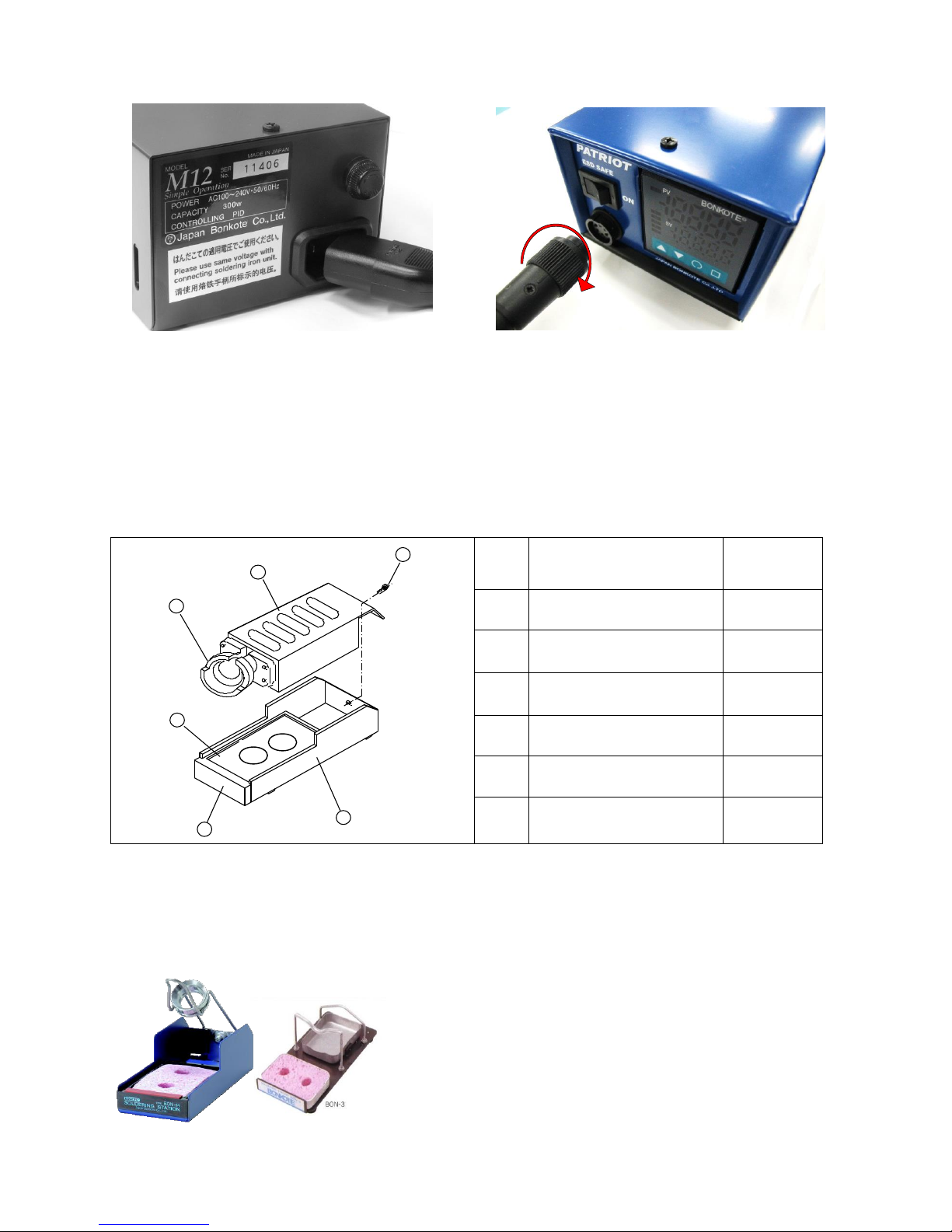
5-C:How to assemble
①Insert the power cord into the 3 pin inlet at the back face.
②Connect the soldering iron to 5 pin connector at the front, and turn the connector housing
clockwise to lock it in place.
③Assemble the iron stand and store the soldering iron in its holder ①.
1
2
3
5
6
4
No.
Name
Model No.
1
Holder
B-11
2
Cover
-
3
Screw with spring-
washer
M4 x 6
4
Cleaner case
K-5
5
Cleaner base
-
6
Cleaning sponge
S-6
Assemble order
Ⅰ:Remove the screw ③from the cleaner base ⑤.
Ⅱ:Align a screw hole of the holder ①and the cleaner base ⑤, then tighten the screw.
Iron stand BON-14 is for TB-1175 iron,
BON-3 is for TB-1100.
①
②
BON-14 BON-3
5
5-D:How to use
①Turn on power
Insert the power plug into the receptacle. Confirm each input voltage of the soldering iron and
the controller is the same, then turn on the power.
※Do not use a 100V soldering iron with 220V power source. Failure to do so may damage the
heater.
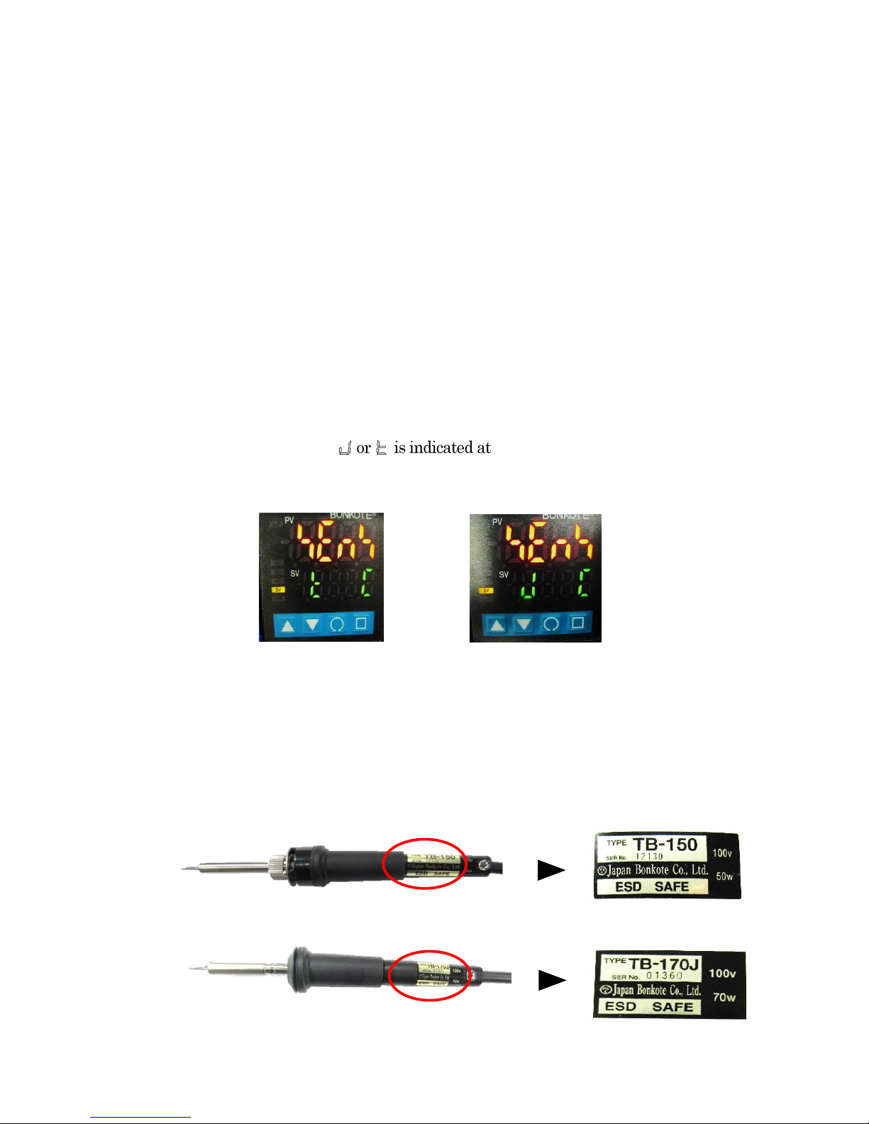
②Setting and confirmation of the sensor type
M12 Controller is workable for 2 different kinds of soldering iron, one is type J sensor and the
other type K sensor. Please make sure that the each sensor type of the soldering iron and that of
the controller should be the same. Otherwise temperature control is unable to work.
※The sensor type of controller and soldering iron is adjusted the same at the shipment.
The sensor type of controller itself is type K at the shipment.
②-1 How to confirm the sensor type.
Controller part
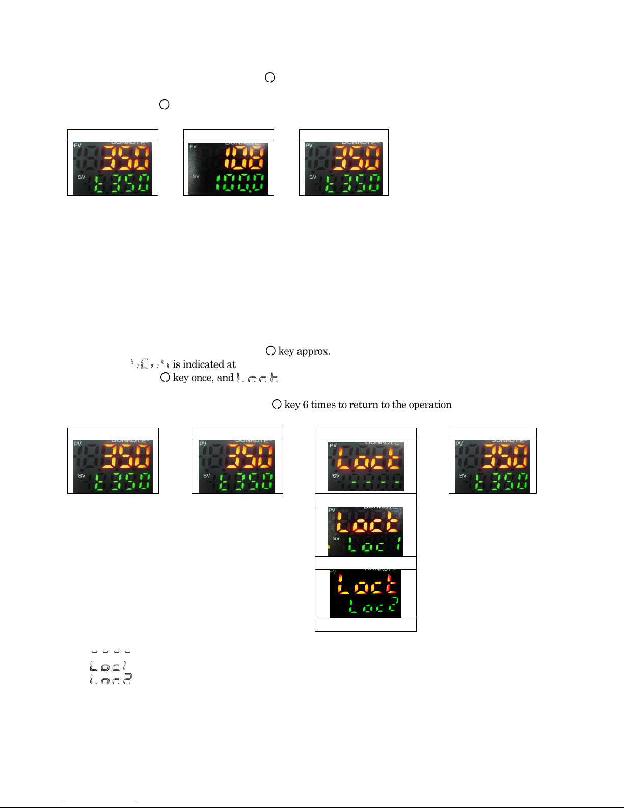
At the operation mode, SV display as show below.
Check the sensor type of the controller whether it is the same as that of a connected
soldering iron.
《Type K 》《Type J 》
Soldering iron
There are 2 different kinds of sensor type, which are type J and type K.
Please check the label of the soldering iron.
Type J soldering iron has a capital letter “J” as below.
TYPE K soldering iron
TYPE J soldering iron

6
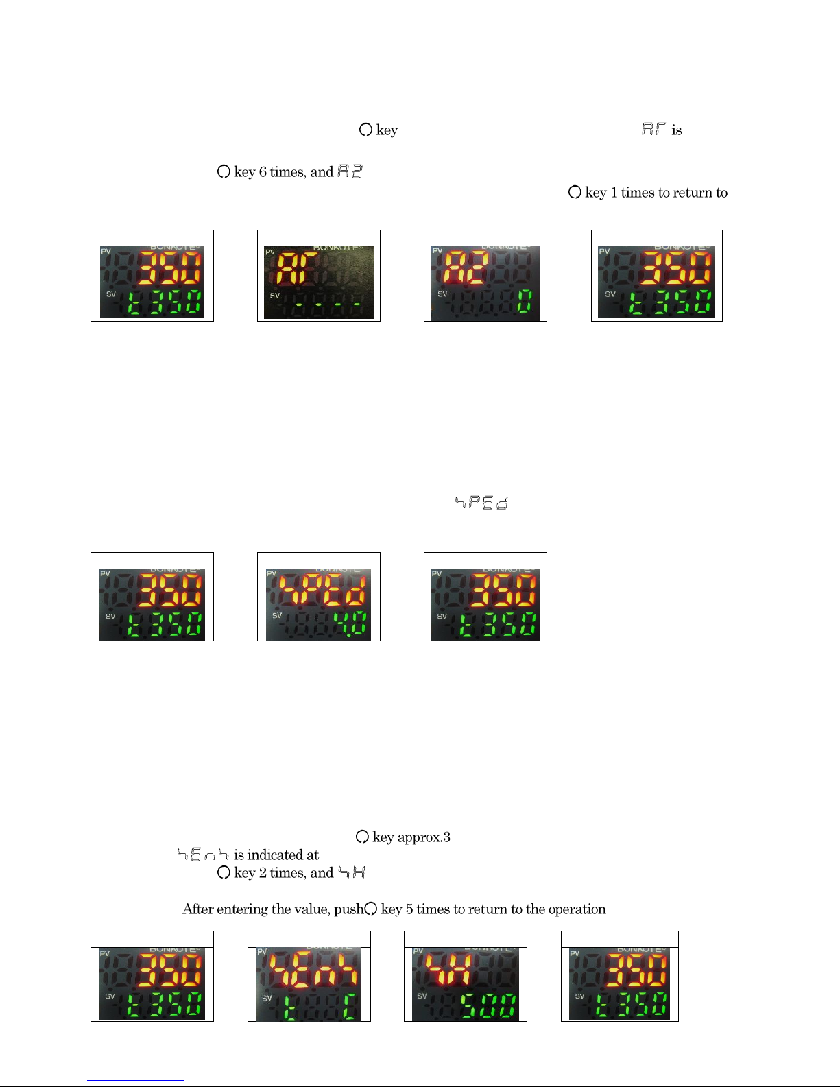
②-2 How to set the sensor type
Ⅰ:At the operation mode, press key approx. 3 seconds while pressing ▽key.
is indicated at PV display.
Ⅱ:Enter suitable sensor type by △key or ▽key, then push
mode.
Operation modee
⇒
Input screen
⇒
Select sensor type
Operation modee
⇒
TYPE K
( ℃)
⇒
TYPE J
( ℃)
③Set the set temperature
Default:350℃Setting range:0 ~500℃
Default:200℃※when「BNJT7」type iron tip equipped.
Ⅰ:At the operation mode, press key once, and is indicated at PV display.
Ⅱ:Enter the desired temperature by △key or ▽key.
Ⅲ:Press key once to return to the operation mode.
Operation modee
⇒
Setting temp.
⇒
Operation mode
④Temperature compensation
Default:0℃Setting range:-100.0℃~100.0℃
Ⅰ:At the operation mode, press seconds while pressing ▽key.
is indicated at PV display.
Ⅱ:Press key 3 times, and is indicated at PV display.
Ⅲ:Enter the desired value by △key or ▽key at SV display.
Ⅳ:After entering the value, push key 4 times to return to the operation mode.
Operation mode
Input screen
Compensation screen
Operation mode
⇒
⇒
⇒
How to calculate the compensation value with a standard thermometer.
e.g.:Thermometer value:「350℃」Controller value:「355℃」Compensation value is「-5」
Compensation value =Thermometer value -Controller value ⇒「350」-「355」=「-5」

7
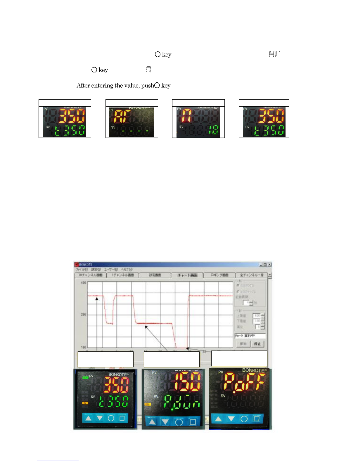
⑤Start Auto Tuning
after reach to the set temperature
Ⅰ:At the operation mode, press for 3 seconds while pressing △key, and
is indicated at PV display.
Ⅱ:Push △key once, and is indicated at SV display, too.
Ⅲ:Push key to startAuto Tuning. (“AT” lamp starts blinking. )
Auto Tuning function completes in about 2 minutes. (“AT” lamp stops blinking.)
Auto Tuning function automatically calculates the suitable PID value which controls soldering irons.
Make sure to implement Auto Tuning function to make soldering irons perform with enough effect.
ATTNTION
After reach to the set temperature
, please implement Auto Tuning function.
Do not touch the soldering iron in operation.
The fluctuation in temperature of soldering iron automatically calculates PID value. Thus, touching
the soldering iron in operation causes incorrect PID value calculation and the soldering iron may not
perform with enough effect. Auto Tuning completes when “AT” lamp stops blinking.
Above ④and ⑤are unnecessary to do every time. Do it when iron tips or set temperature are
changed.
※At shipment, Auto Tuning function has NOT done yet. Make sure to do it at the first time to use.
6. Optional functions
M12 controller has various functions. Please use them with your convenience.
6-A:Alarm function Upper limit setting
Set the upper limit of operation temperature range
Default:0℃
Ⅰ:At the operation mode, press for 3 seconds while pressing △key, and is indicated
at PV display.
Ⅱ:Push key 5 times, and is indicated at PV display.
Ⅲ:Enter the desired value by △or ▽key at SV display. Push key 2 times to return to the
operation mode.
This function can alarm when the operation temperature exceeds the upper limit you set up.
e.g. Controller set temperature: 「350℃」and Upper limit temperature: 「100℃」
When the operating temperature exceeds 「450℃」at above condition, it will work.
Operation modee
⇒
Auto Tuning
⇒
AT setting screen
⇒
Operation modee
Operation mode
⇒
Auto Tuning
⇒
Upper limit alarm
⇒
Operation mode
8
6-B:Alarm function Lower limit setting
Set the lower limit of operation temperature range
Default:0℃
Ⅰ:At the operation mode, press for 3 seconds while pressing △key, and
indicated at PV display.
Ⅱ:Push is indicated at PV display.
Ⅲ:Enter the desired value by △or ▽key at SV display, then push
the operation mode.
This function can alarm when the operation temperature exceeds the lower limit you set up.
e.g. Controller set temperature: 「350℃」and Upper limit temperature: 「-100℃」
When the operating temperature exceeds 「-250℃」at above condition, it will work.
6-C:Temperature Recovery speed
Adjust the recovery speed to the set temperature.
Default:4.0Setting range:1.0~10.0
Ⅰ:At the operation mode, press □key once, and is indicated at PV display.
Ⅱ:Enter the desired value by △or ▽key at SV display.
Ⅲ:After entering the value, push □key once to return to the operation mode.
Set value: 1.0 Recovery speed is fast, but overshooting becomes large.
Set value: 10.0 Recovery speed is slow, but overshooting becomes small.
6-D:Upper limit of set temperature
Set the upper limit of set temperature
Default:500℃Setting range:0 ~500℃
Ⅰ:At the operation mode, press seconds while pressing ▽key, and
PV display.
Ⅱ:Push is indicated at PV display.
Ⅲ:Enter the desired value by △key or ▽key at SV display.
Ⅳ:mode.
Operation mode
⇒
Auto Tuning
⇒
Lower limit alarm
⇒
Operation mode
Operation mode
⇒
Recovery speed
⇒
Operation mode
Operation mode
⇒
Input screen
⇒
Upper limit temp.
⇒
Operation mode
9
6-E:Manipulated output value
Monitoring the output amount of heater
Ⅰ:At the operation mode, press key about 3 seconds , and operation output amount
(0~100%) is indicated at SV display.
Ⅱ:Push key to return to the operation mode.
6-F:Lock function
Lock the set values to prevent error setting Default:-
Ⅰ:At the operation mode, press 3 seconds while pressing ▽key.
PV display.
Ⅱ:Push is indicated at PV display.
Ⅲ:Enter the desired function by △key or ▽key at SV display.
Ⅳ:After entering the value, push mode.
:LOCK-NON
:Only LOCK FUNCTION is available
:LOCK FUNCTION and Changing set temperature are available
Operation mode
⇒
Output amount
⇒
Operation mode
Operation mode
1⇒
Input screen
る
⇒
⇒
⇒
Lock select screen
⇒
Operation mode
LOCK - NON
LOCK - 1
LOCK - 2
10
6-G:Anti reset wind up setting
Control the overshooting
Default:18% Setting range:0 ~100%
Ⅰ:At the operation modee, press for 3 seconds while pressing △key. is
indicated at PV display.
Ⅱ:Push 4 times , and is indicated at PV display.
Ⅲ:Enter the desired value by △key or ▽key at SV display.
Ⅳ:3 times to return to the operation mode.
We recommend that you should keep the default. The lower value than the default can restrain
overshooting, but there might be possible not to recover to the set temperature.
6-H:Auto Power Down / Auto Power Off
In order to prevent soldering iron tips from Deterioration and Oxidization, the tip
temperature is lowered ( Power Down), and the supplying electric power to the heater is
stopped (Power Off) automatically when the tiptemperature does not change for a certain
period of time (User- settable). This function is not only effective for saving energy, but
also for safety.
Operation mode
⇒
Auto Tuning
⇒
Anti reset wind up
⇒
Operation mode
Operation mode
Power Down
Power Off
11
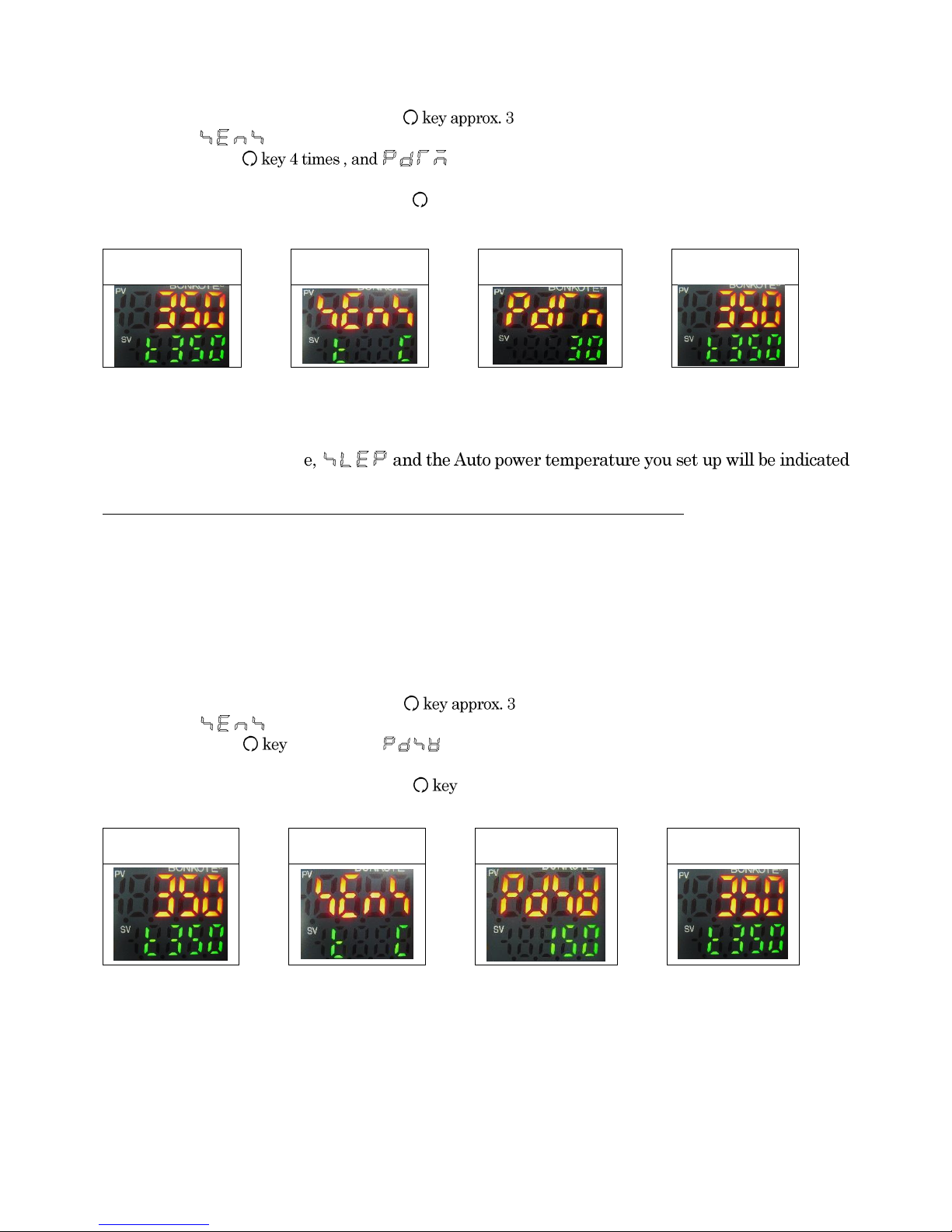
①Auto Power Down time
Default:30 minutes Setting range:0 ~120 minutes
Ⅰ:At the operation mode, press seconds while pressing ▽key.
is indicated at PV display.
Ⅱ:Push is indicated at PV display.
Ⅲ:Enter the desired value by △key or ▽key at SV display.
Ⅳ:After entering the value, push key 3 times to return to the operation mode.
This function lowers the tip temperature automatically when the temperature is no change for more
than a certain period of time you set up, since the controller recognizes that the soldering iron is
inactivity. During this mod
alternately.
If unnecessary, set the value “0” (zero), and this function becomes ineffective.
②Auto Power Down temperature
Default:150℃Setting range:0 ~(set temp.) -1℃
Ⅰ:At the operation mode, press seconds while pressing ▽key.
is indicated at PV display.
Ⅱ:Push 5 times , and is indicated at PV display.
Ⅲ:Enter the desired value by △key or ▽key at SV display.
Ⅳ:After entering the value, push 2 times to return to the operation modee.
The tip temperature falls down and stands by at the specific temperature you set up.
e.g. If you set up 「150℃」, the temperature drops and stands by around 「150℃」when not in
use. In case the operation temperature is 「350℃」, Auto PowerDown temperature can be set under
349℃only.
Operation mode
⇒
Input screen
⇒
Auto power down
time setting screen
⇒
Operation mode
Operation mode
⇒
Input screen
⇒
Auto power down
temp. setting screen
⇒
Operation mode

12
③Auto Power Off time
Default:30 minutes Setting range:0~120 minutes
Ⅰ:At the operation mode, press seconds while pressing ▽key.
is indicated at PV display.
Ⅱ:Push is indicated at PV display.
Ⅲ:Enter the desired value by △key or ▽key at SV display.
Ⅳ:After entering the value, push mode.
During Auto Power Down mode, SV display, this function turn off the power
of controller automatically when the tip temperature is no change for more than a certain period of
time you set up, since the controller recognizes that the soldering iron is inactivity.
If unnecessary, set the value “0” (zero), and this function becomes ineffective.
④Exiting Auto Power Down mode
Press △key or ▽key more than 3 seconds to return to the operation mode.
Temperature deviation by more than 5℃can release Auto power down mode.
e.g. Touch the iron tip with a moisturized sponge.
⑤Exiting Auto Power Off mode
Turn on the power again.
⑥Manual operation
After the tip temperature has reached to the set temperature, at the operation mode, press
△key or ▽key approx. 3 seconds to enter the power down mode.
At the power down mode, press △key or ▽key approx. 3 seconds to release the mode and
return to the operation mode.
Operation mode
⇒
Input screen
⇒
Auto Power Down
time setting screen
⇒
Operation mode

13
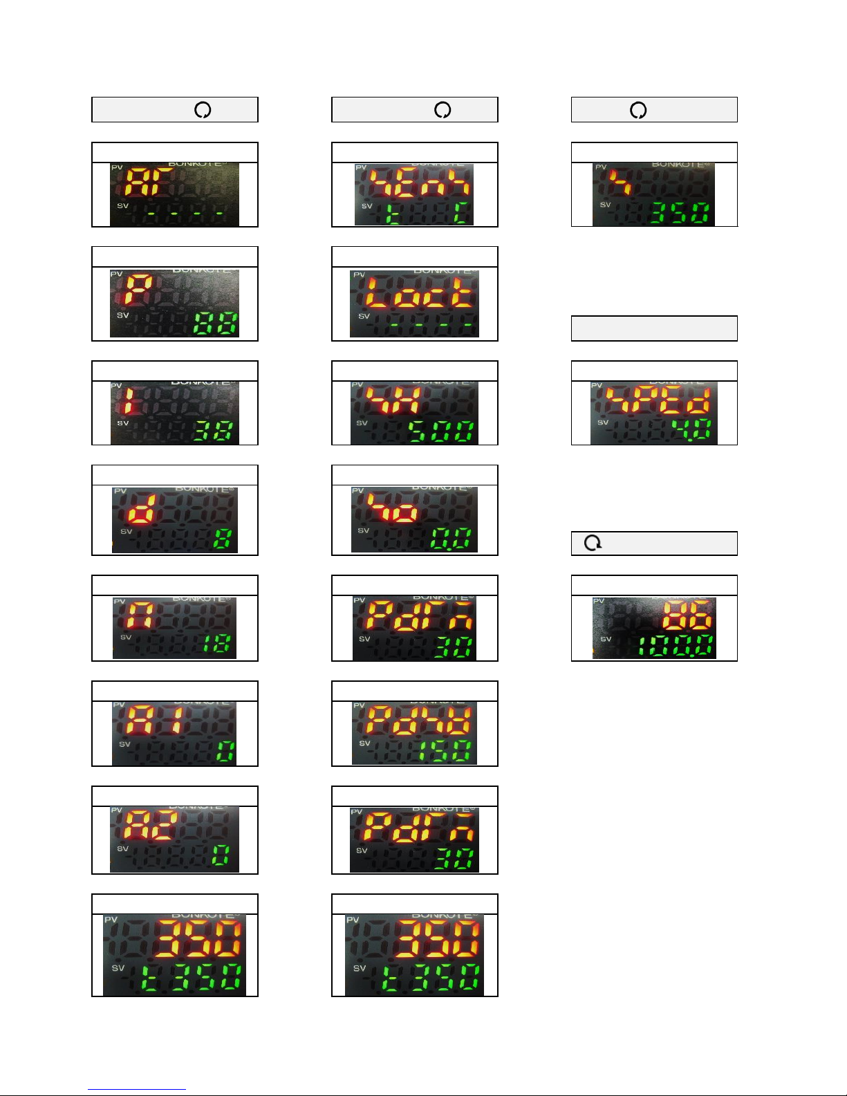
6-I:PID value manual setting
M12 controller is basically unnecessary PID setting becauseit comes standard withAuto Tuning function.
In case of Overshoot or special soldering work, you can set PID value by manual.
Please use PID manual setting with your convenience.
①Proportional band
Default:88℃Setting range:0 ~1570℃(type J:0~1200℃)
Higher set value can reduce overshoot, however, it makes temperature recovery time longer
and temperature reduction during soldering work larger.
Ⅰ:At the Operation mode, press for 3 seconds while pressing △key. is
indicated at PV display.
Ⅱ:Push key once, and is indicated at PV display.
Ⅲ:Enter the desired value by △key or ▽key at SV display, then push key 6 times to
return to the operation mode.
②Integration time
Default:38 seconds Setting range:0 ~3600 seconds
Higher set value can reduce overshoot, however, it makes temperature recovery time longer
and temperature reduction during soldering work larger.
Ⅰ:At the Operation mode, press for 3 seconds while pressing △key.
indicated at PV display.
Ⅱ:Push key 2 times, and is indicated at PV display.
Ⅲ:Enter the desired value by △key or ▽key at SV display, then push
return to the operation mode.
Operation mode
⇒
Auto Tuning
⇒
Proportional band
⇒
Operation mode
Operation mode
⇒
Auto Tuning
⇒
Integration time
⇒
Operation mode

14
③Derivative time
Default:8 seconds Setting range:0 ~1800 seconds
Lower set value can reduce overshoot, however, it makes temperature recovery time longer.
This value is supposed to be set or adjusted after value “P” and “I” are almost fixed.
Ⅰ:At the Operation mode, press for 3 seconds while pressing △key.
indicated at PV display.
Ⅱ:Push
Ⅲ:Enter the desired value by △key or ▽key at SV display, then push
return to the operation mode.
Operation modee
⇒
Auto Tuning
⇒
Derivative time
⇒
Operation mode
15
7. Character List
△key +key
▽key +key
key
↓
↓
↓
Auto Tuning
Input screen
Setting temperature
↓
↓
Proportional band
Lock function
□key
↓
↓
↓
Integration time
Upper limit temp.
Recovery speed
↓
↓
Derivative time
Compensation screen
key long press
↓
↓
↓
Anti reset wind up
Auto Power Down time
Operation amount output
↓
↓
Upper limit alarm
Auto Power Down temp.
↓
↓
Lower limit alarm
Auto Power Off time
↓
↓
Operation mode
Operation mode

16
8. How to maintenance
How to replace a fuse
Loosen a fuse holder and remove it.
Check the fuse if it needs to be
replaced to a new one.
Model No.
Specification
Fuse 3A
Glass fuse 250Ⅴ3A(φ5.2×20mm)
9. Standard specification
Input voltage
100VAC ~240VAC
Temperature range
0~500℃
Power cord
100VAC:3pin 3PCHI plug cord
220VAC: 3pin 3EPV plug cord
Dimension
97(W)×130(D)×73(H)mm
Weight
≦750 g
Fuse
3A
Temperature control
method
PID control ( Auto Tuning )
Temperature
indication
PV display:LED(RED)SV display:LED(GREEN)
Error indication
“ ̄ ̄ ̄ ̄” Over scale :Temperature exceed the upper
limit of temperature range.
※Error of sensors
“____” Under scale :Temperature exceed the lower
limit of temperature range.
※Reversed polarity of sensors
Material ( case )
Steel
Power consumption
≦10VA ( controller only )
17
10. Guarantee and after sales service
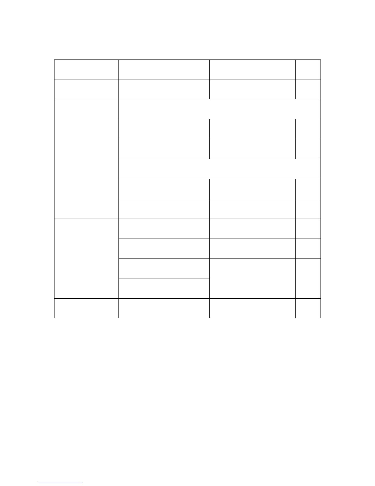
10-A:Trouble shooting
Symptom
Probable cause
Measures
page
“----”is blinking at
PV display
Tip sensor is disconnected or comes off
the iron unit.
Replace iron tips
Soldering iron does not
heat
※No power to controller
Power cord is NOT connected with the
receptacle.
Power switch is NOT ON.
Check the power cord or power switch
again.
P4
Blown fuse
Replace the fuse.
P15
※Power is ON
Soldering iron and controller is NOT
connected properly.
Check the connection again.
P4
The heater element is consumed.
Replace the heater.
Unstable temperature
Sensor type of controller and soldering
iron are NOT matched.
Match the sensor type of controller
and soldering iron.
P5
Auto Tuning function is NOT
implemented.
Implement Auto Tuning function.
P7
Temperature does NOT reach the set
temperature.
Adjust the value of recovery speed.
Implement Anti reset wind up
function.
P8
P10
Overshooting is large.
Key operation is unable
Lock functions are ON.
Check the lock functions.
P9
10-B:Guarantee
Our products are shipped after sever factory tests and inspections.
However, if you find malfunctions or defects due to problems in workmanship or transportation,
please contact your dealers or us.
The guarantee period of your products is in one year after your purchase, except for
replacement parts.
10-C:After sales service
When you think your system does not operate properly, read this manual again to check.
If still troubles are not solved, please contact your dealers or us.

®
JAPAN BONKOTE CO., LTD.
600-14 Kasahara, Mito, Ibaraki, 310-0852 JAPAN
TEL : +81-29-241-2725
FAX : +81-29-241-2726
http://bonkote.co.jp
Email: info@bonkote.co.jp
This manual suits for next models
1
Table of contents
Other BONKOTE Controllers manuals


Popular Controllers manuals by other brands


Siemens
Siemens SIRIUS S2 owner's manual

Digital Loggers
Digital Loggers Ethernet Power Controller II user guide

Parker
Parker ACR Series Programmer's guide

Interactive Technologies
Interactive Technologies SceneStation 3 user manual

sauter
sauter NRT405F901 manual

Swann
Swann Smith's TCAS T1 Installation and user guide


