bono Cannon UNI-MATIC UM 30 Product guide

FLASH COIL STEAM GENERATORS UNI-MATIC
Technical Book Steam Generators UM
2
1. General Information
2. Competitive Advantages
3. Technical Specifications
4. P&ID
5. Dimensions and Connections
6. Generator Layout
7. Installation
8. Maintenance
9. Scope of Supply
10. Appendix 1. Fuel consumption calculation
11. Appendix 2. Thermodynamic characteristics of
saturated steam
FLASH COIL STEAM GENERATORS UNI-MATIC

3

4
Flash coil steam generators of the series UNI-MATIC
(UM) with forced circulation guarantee a steam
production range between 300 and 3000 kg/h; design
pressure is up to 12 bar.
Models of the steam generators series UNI-MATIC:
• UM 30: up to 300 kg/h
• UM 50: up to 500 kg/h
• UM 100: up to 1.000 kg/h
• UM 150: up to 1.500 kg/h
• UM 200: up to 2.000 kg/h
• UM 300: up to 3.000 kg/h
UM-UNIMATIC UM flash coil steam generators’ fields
of application are laundries, texile industry, food &
beverage, rubber, cellulose industry, agrotechnology,
woodworking and others.
UNI-MATIC UM generators are supplied as packaged
units, complete with all necessary equipment and
ready to be connected to site utilities.
As optional, an air preheater can be purchased
additionally to the steam generator.
Preheater enables the boiler to increase efficiency by
2%, therefore reaching 90% at full load.
UM model reaches operating conditions 2-3 minutes
after ignition of the burner.
UNI-MATIC model UM is available both in vertical and
horizontal version - UM compact design is also suitable
for small plants, although always guaranteeing high
quality performances.
UNI-MATIC UM generators are deisgned and produced
according to ISPELS code, PED directive 97/23/CE
Figure 1
Flash Coil Steam Generator UNI-MATIC
UM, vertical version with air pre-heater
1. GENERAL INFORMATION
Figure 2
Flash Coil Steam Generator UNI-MATIC
UM, horizontal version

5
1 Burner 6 Exhaust Gas Outlet
2 Burner Fan 7 Drain
3 UNI-MATIC Inner Coil 8 Steam Outlet Flange
4 Burner Flame 9 Water Inlet Flange
5 Bottom Refractory
Figure 3
Flash coil steam Generator UNI-MATIC UM functional diagram

6
2. COMPETITIVE ADVANTAGES
Figure 4
Safety and control instruments on an horizontal
UNI-MATIC UM steam generator.
Figure 5
Control panel for UNI-MATIC UM steam generator.
•Two versions: vertical and horizontal
•Maximum efficiency and high reliability
•Easy maintenance. The upper cover facili-
tates inspection and cleaning of the combus-
tion chamber and the internal parts of the
steam generator.
•Fast to reach operating conditions. Thanks
to the absence of thermal inertia, UNI-MATIC
UM steam generator is highly efficient in peri-
odic processes. It takes 2÷3 minutes to reach
operating condition after burner ignition.
•High reliable supply of feeding water.
Feeding pump flow sections are made of
Kevlar, a syntetic composite material which
guarantees maximum reliability and efficient
supply of feeding water.
•Easy-to-use and reliable automatic combus-
tion regulation with the following regulating
types:
• “on/off” regulation of gas fuel feeding
to the burner, burner air vent and feeding
water pump. Liquid fuel supply to burner
nozzle is achieved through electromagnetic
opening/closing valve.
• two-stages regulation (1st stage - min.
50%, 2nd stage - 100%), through regulation
of the amount of air and gas in the com-
bustion chamber, regulation of feed wa-
ter supply with two-position valves on the
fuel, air and water lines combined with on/
off regime of water and gas supply. Liquid
fuel supply to burner’s nozzle is achieved
through an opening/closing valve.
modulating regulation of steam produc-
tion with 30-100% range, achieved with an
electronic control of air and fuel supply and
servocontrolled valves. Feeding water sup-
ply is regulated through plunger pump with
frequency transformer. Liquid fuel oil sup-
ply to burner’s nozzle is achieved through
opening/closing electromagnetic valve with
fuel pressure regulation through a bypass
valve.
•Safety. The quantity of water, and thus steam,
is limited, allowing therefore a high level of
safety for personnel if compared to standard
steam boilers types.

7
3. TECHNICAL SPECIFICATIONS - CAPACITY AND CONSUMPTION
Table 1
Technical Specifications of steam generator UNI-MATIC UM.*
UNIMATIC – TECHNICAL DATASHEET
Features Unit UM 30 UM 50 UM 100 UM 150 UM 200 UM 300
Steam production Kg/h 300 500 1.000 1.500 2.000 3.000
Design pressure bar 11,7 11,7 11,7 11,7 11,7 11,0
Max working pressure bar 10.0 10.0 10.0 10.0 10.0 9.0
TOTAL ELECTRIC POWER
Heavy fuel oil KW 4,3 5,3 9,6 12,9 16,0 24,0
Natural gas or diesel oil KW 2,3 2,3 4,6 5,9 7,0 12,0
FUEL CONSUMPTION AT 100% OF THE LOAD
Heavy fuel oil Kg/h 21,1 35,1 70,3 105,4 140,6 210,9
Natural gas Nm3/h 24,1 40,1 80,2 120,3 160,4 240,6
Diesel oil kg/h 20,1 33,4 66,8 100,3 133,7 200,5
FUEL CALORIFIC POWER
Heavy fuel oil Kcal/kg 9.700
8.500
10.200
Natural gas Kcal/Nm3
Diesel oil Kcal/kg
Standard electric
power data 380 V / 50 Hz / 3 phases with neutral
Auxiliaries voltage 220 V
Feeding and boiler
water norm EN 12952 – 12:2003 (up to European standard)
* - These are generalized technical information for all UNI-MATIC range model.
Please ask for specific measures indications and eventual available modifications.

8
3. TECHNICAL SPECIFICATIONS - THERMAL EFFICIENCY
Figure 6
The coefficient of performance (COP) of the boiler UNI-MATIC UM crossed with the load, under different
working pressures. Air preheater not included.

9
Figure 7
A plot of the coefficient of performance (COP) of the boiler UNI-MATIC UM with air preheater.
10
The generator must be supplied with water with
hardness less than 0.1° F made up of the condensation
recovery and the make-up water softened by a
purifier (cation resin) or demineralised. The water
supply must always come from the supply tank; a
direct connection to the mains water or to the purifier
is not allowed.
The suction piping must be as straight as possible
and its diameter must be larger than that of the
connection on the pump (see connection diagram).
The supply water must be at a temperature of at least
70° C as lower temperatures cause deterioration in
the generator coils.
If the water temperature is lower than the value
indicated above the supply water must be heated.
The tank capacity must be adequate for the boiler
capacity and normally at least the same as the
consumption of an hour operation at maximum load.
The tank must be fitted with a drainage tube with
cock direct to the sewers for regular drainage and to
empty the tank for cleaning.
Water pump must not suck from the bottom of the
tank but slightly higher to avoid the entry of impurities.
If the oxygen scavenger is required please refer to
the technical specifications of the product in use.
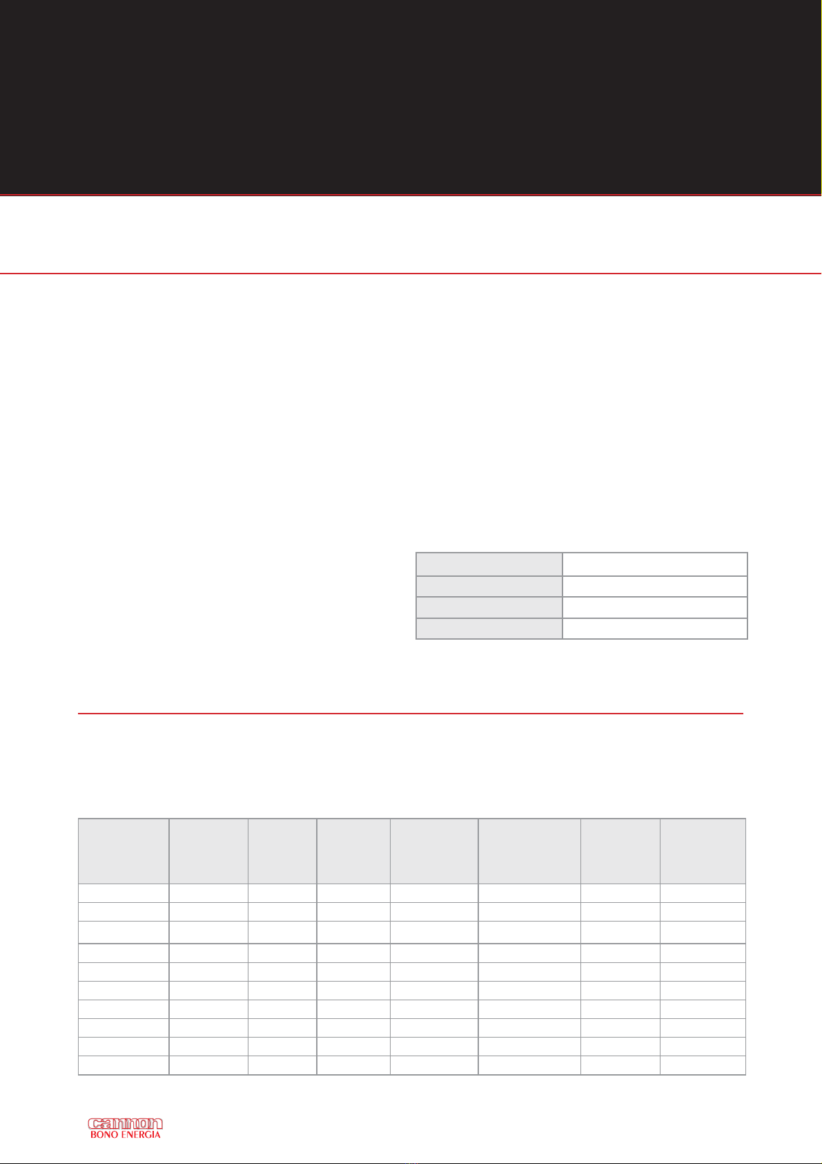
Total hardness Less than 0,05 °F
pH 8.5-10.0
Alkalinity Max 1000 ppm
Silicone (Si O2) Max 100 ppm
Table 2
Water supply specifications. In order to maintain
its best performance the steam generator must
be supplied with water conforming to the below
specifications.
Table 3
Minimum pressure / suction head for water. The tank must be raised up and have sufficient head for correct
pump operation and to avoid phenomena of cavitation due to insufficient supply
Temperature
°C
Had Height
mH2O
Pressure
bar
Pressure
MPa
Temperature
°C
Liquid Column
Height
mH2O
Pressure
bar
Pressure
MPa
0 0.00 0.00 0.00 50 1.25 0.12 0.012
5 0.00 0.00 0.00 55 1.75 0.17 0.017
10 0.00 0.00 0.00 60 2.00 0.20 0.02
15 0.20 0.02 0.002 65 2.50 0.25 0.025
20 0.20 0.02 0.002 70 3.00 0.29 0.029
25 0.25 0.02 0.002 75 4.00 0.39 0.039
30 0.50 0.05 0.005 80 5.00 0.49 0.049
35 0.80 0.08 0.008 85 6.00 0.59 0.059
40 0.90 0.09 0.009 90 7.00 0.69 0.069
45 1.00 0.10 0.01 95 9.00 0.88 0.088
3. TECHNICAL SPECIFICATIONS - WATER SUPPLY REQUIREMENTS
11
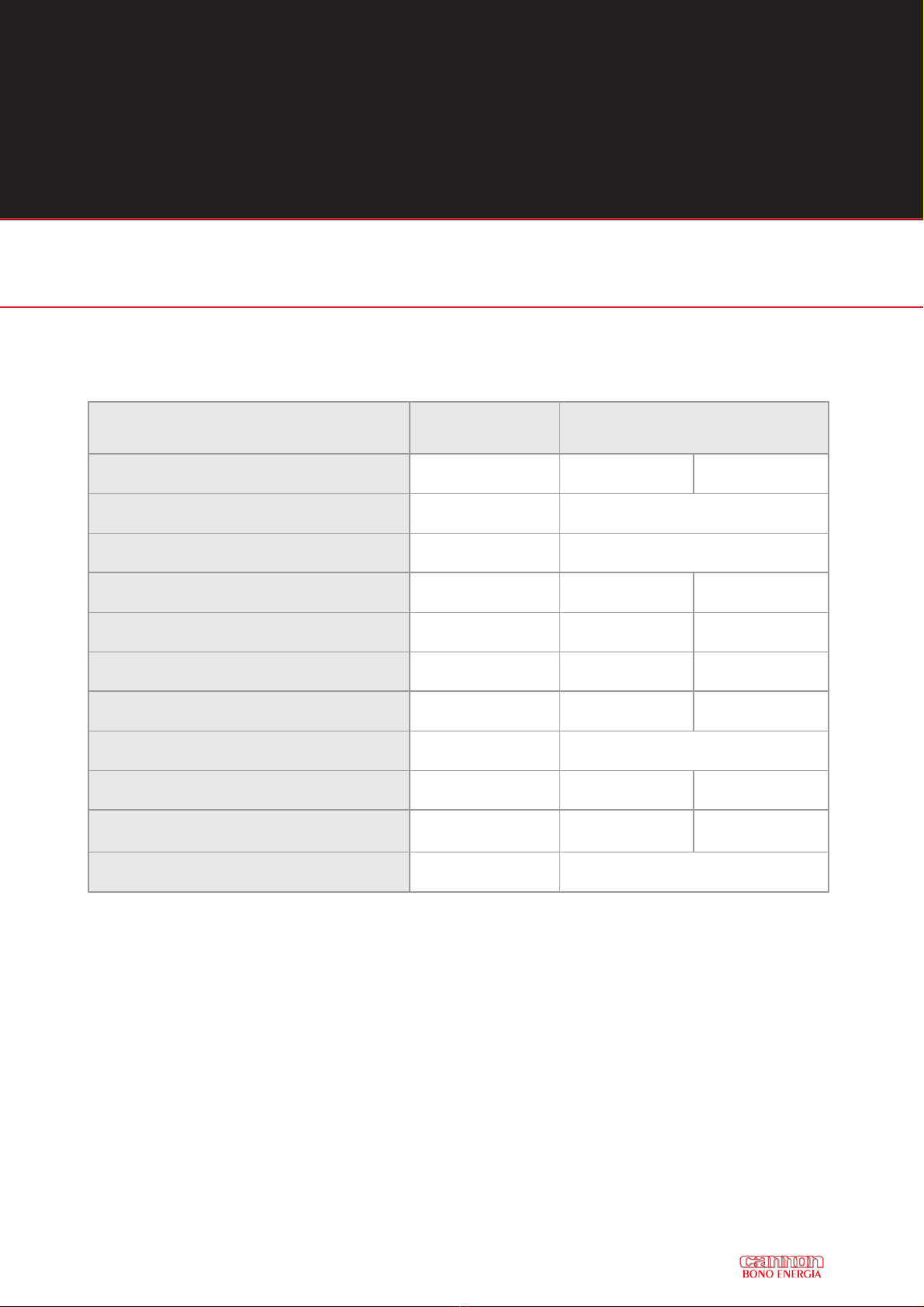
Table 4
Feedwater Quality Requirements for best UNI-MATIC UM operation and preservation
(a) with copper alloys in the system the pH value shall be maintained in the range be from 8.7 to 9.2
(b) with softened water pH value >7.0 - see the manual of the boiler
(c) If the operating pressure is <1 bar, the max total acceptable hardness should be 0.05 mmol / l
(d) Instead of observing this value at intermitted operation or operation without deareator if forming agents and/or excess
of oxygen scavenger shall be used.
(e) Organic substances are generally a mixture of several different compounds. The composition of such mixtures and
behaviour of their individual components under the conditions of boiler operation are difficul to predict.
Organic substances may be decomposed to form carbonic acid or other acidic decomposition products which increase the
acid conductivity and cause corrosion or deposits. They also may lead to foaming and/or priming which shall be kept as
low as possible.
PARAMETERS UNIT FEED WATER PROPERTIES
ACCORDING TO EN 12953
OPERATING PRESSURE (X) bar (= 0,1 MPa) 0,5 < X< 20 X > 20
APPEARANCE / Clean, free from suspended solids
DIRECT CONDUCTIVITY AT 25°C μS/cm Not specified
pH VALUE AT 25 °C (a) / >9,2 (b) >9,2 (b)
TOTAL HARDNESS (Ca + Mg) mmol/l <0,01 (c) <0,01
IRON (Fe) CONCENTRATION mg/l <0,3 <0,1
COPPER (Cu) CONCENTRATION mg/l <0,05 <0,03
SILICA (SiO2) CONCENTRATION mg/l Not specified
OXYGEN (O2) CONCENTRATION mg/l <0,05 (d) <0,02
OIL/GREASE CONCENTRATION
(see EN 12953-6) mg/l <1 <1
ORGANIC SUBSTANCES CONCENTRATION / See footnote (e)
12
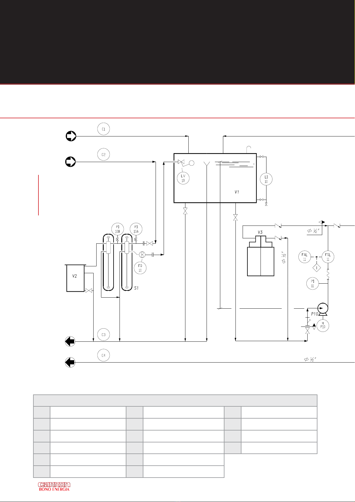
4. P&ID
UM – P&ID Elements Description
B1 Steam Generator UM S1 Water Softener C3 Drain to Sewer Pipe
L1 Chimney V1 Feed Water / Condensate Tank C4 Drain to Hot Pit Pipe
QE Electrical Cabinet V2 Brine Tank C5 Steam to User Pipe
D1 Instrument Header V3 Chemical Dosing Station F1 Feed Fuel Pipe
D2 Steam Separator C1 Condensate Return Pipe
P10 Feed Water Pump C2 Feed Water Pipe
Figure 8
The data processing schemes are
standardized to the entire UNI-
MATIC range; further measurements
and modifications are available on-
demand.

13
UM – P&ID Ancillaries Symbols Meaning
LV Level Valve MMotor TI Temperature Indicator
LI Level Indicator PAH Pressure Alarm High TAH Temperature Alarm High
PI Pressure Indicator PAHH Pressure Alarm High Above PAH TAHH Temperature Alarm High Above TAH
FQ Flow Indicator Totaliser PSH Pressure Switch High TSH Temperature Switch High
FAL Flow Alarm Low PSHH Pressure Switch High Above PSH TSHH Temperature Switch High Above TSH
FSL Minimum Flow Switch PSV Pressure Safety Valve
SUPPLY LIMIT
CANNON BONO CUSTOMER
14
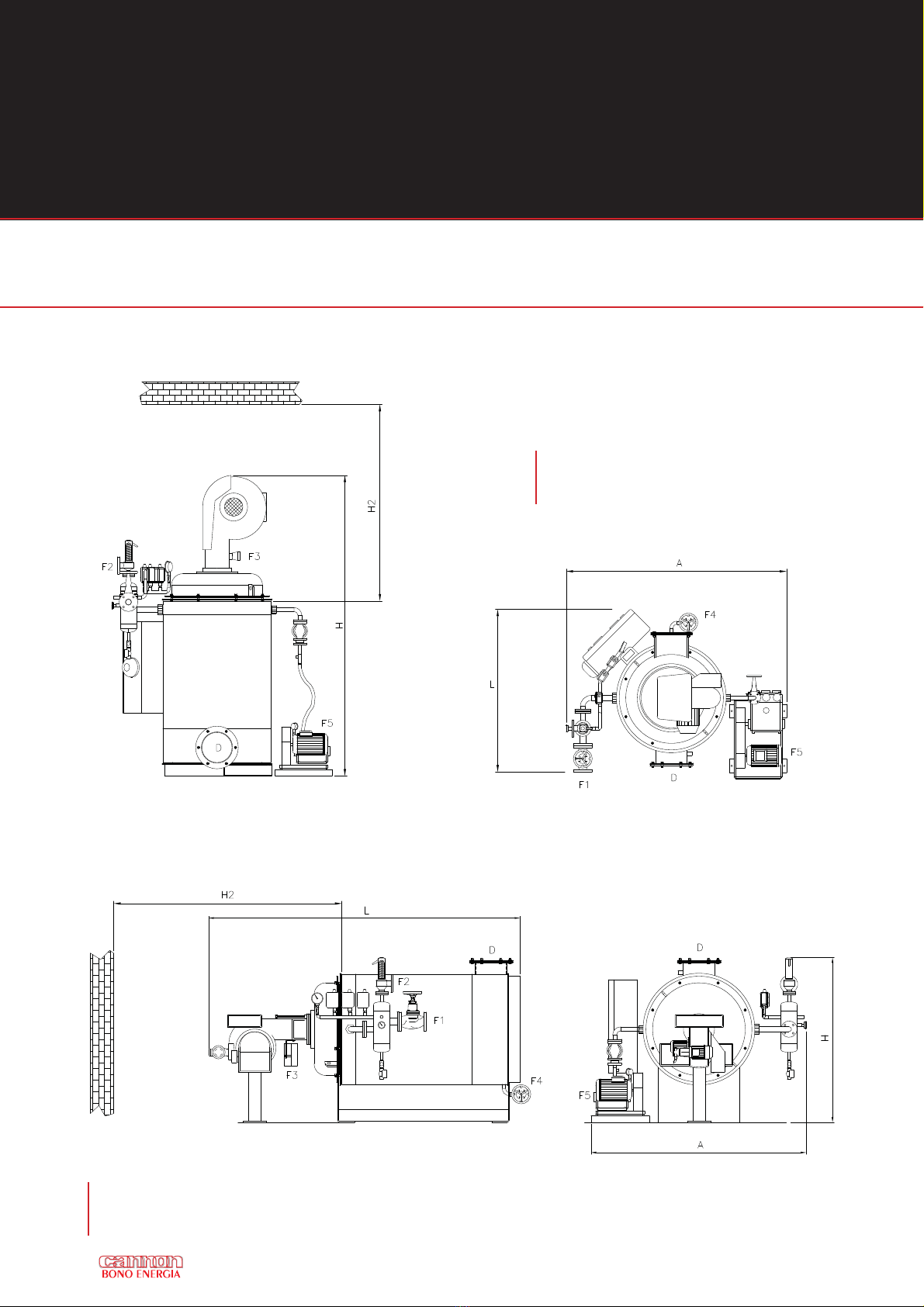
5. DIMENSIONS AND CONNECTIONS
Figure 10
Steam generator UNI-MATIC UM Horizontal
version steam generator overall dimensions
Figure 9
Steam generator UNI-MATIC UM vertical
steam generator overall dimensions
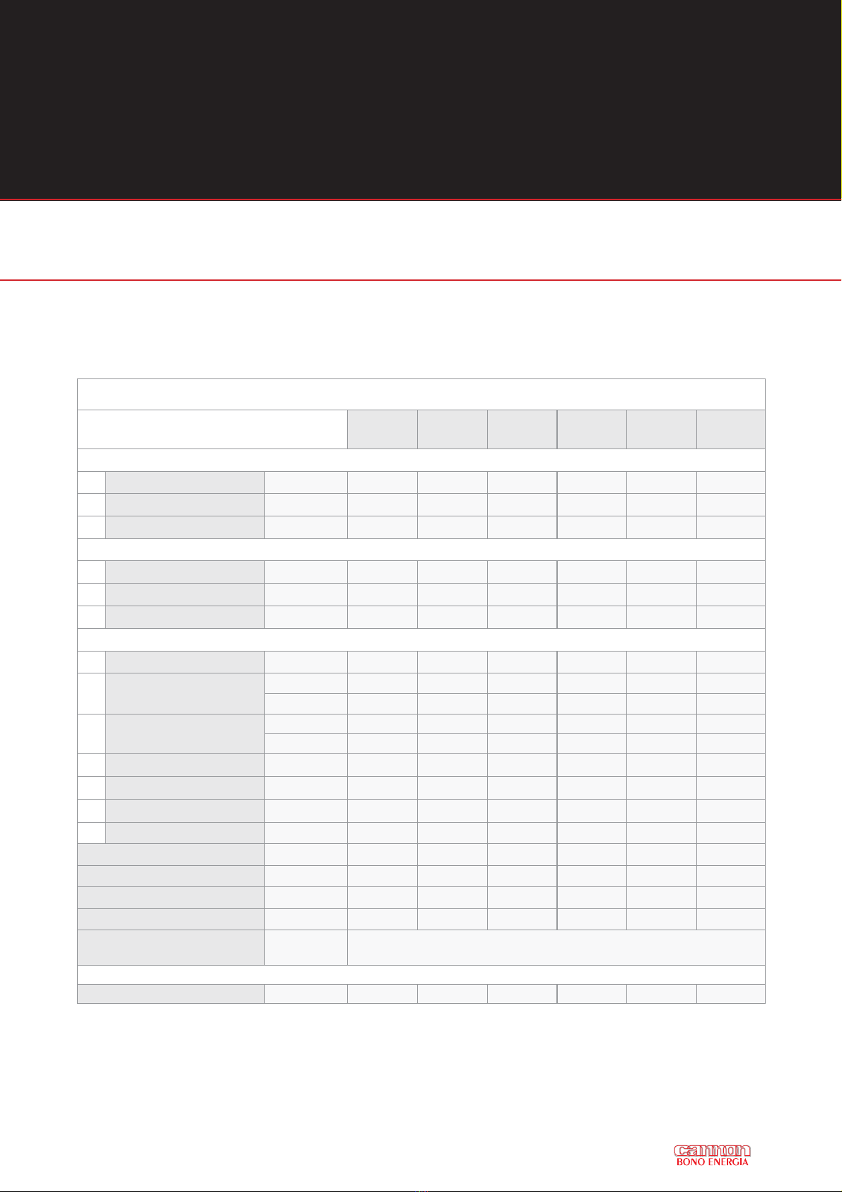
15
Table 5
Dimensions of flash coil steam generators UNI-MATIC UM. These dimensions are generalized to the entire
range of models UNI-MATIC. Measurement and modification are available on-demand.
OVERALL DIMENSIONS AND CONNECTIONS OF STEAM GENERATORS UNI-MATIC UM
MODEL UM 30 UM 50 UM 100 UM 150 UM 200 UM 300
VERTICAL VERSION DIMENSIONS
L Length mm 1450 1550 1800 1900 2100 2700
A Width mm 1350 1350 1700 1700 1800 2000
H Height mm 2100 2100 2660 2750 3400 3750
HORIZONTAL VERSION DIMENSIONS
L Length mm 2100 2100 2660 2750 3400 3750
A Width mm 1350 1350 1700 1700 1800 2415
H Height mm 1450 1550 1800 1900 2100 2385
GENERAL TECHNICAL DATA
D Stack connection mm 125 162 263 314 346 400
F1 Steam outlet DN 32 32 50 50 65 80
PN 16 16 16 16 16 16
F2 Safety valve DN 20/40 20/40 20/40 25/40 25/40 32/50
PN 25/16 25/16 25/16 25/16 25/16 25/16
F3 Natural gas connection 1”G 1 ½”G 2”G 2”G 2”G 2 ½”G
F4 Coil drain outlet ½”G ½”G ½”G ½”G ½”G ½”G
F5 Feed water inlet 1 ¼”G 1 ¼”G 1 ¼”G 1 ½”G 1 ½”G 2”G
H2 Coil extraction distance mm 1100 1300 1750 1950 2000 2700
Total volume l 33 49 79 110 240 271
Pipes diameter mm 33.7 33.7 33.7 33.7/38 33.7/51 38/51
Heating surface m26 8.8 14 18 32 34
Water capacity l/h 345 575 1150 1750 2300 3300
Standard feeding
water temperature °C 70÷95*
Empty weight t 1.2 1.2 1.5 2.0 2.8 3.1
* - In case of feed water temperature above 70 °C, please contact Bono Energia technical specialists for pump flow
section configuration

16
6. GENERATOR LAYOUT
Figure 11
Typical layout of steam gen-
erator UNI-MATIC UM on a
portable device; the trailer is
equipped with a UNI-MATIC
UM, two feed water pumps, a
feed water/condensate return
tank, a booster pump to create
a head for the hot waters de-
riving from condensation and
a chimney.
The trailer hook is orientable.
1 Steam Generator UM 6 Booster Pump
2 Burner 7 Feed Water Pump
3 Steam Generator Chimney 8 Trailer
4 Feed Water/Condensate Tank 9 Trailer Hook
5 Tank Level Indicator

17
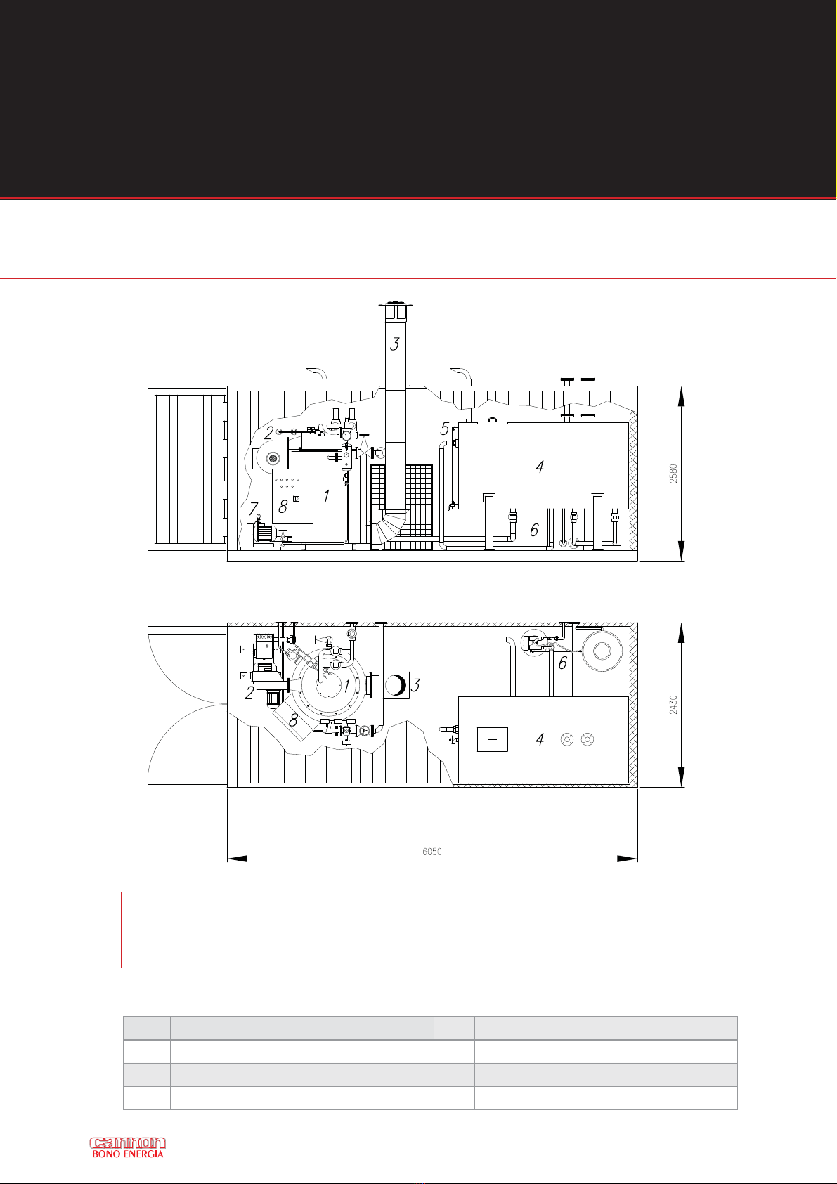
Figure 12
Layout of a UNI-MATIC UM in a container; the container is
equipped with a UM steam generator, an electrical cabinet
mounted on the container’s wall, one feed water pump, a feed
water/condensate return tank, a chimney and a water softening
system.
1 Steam Generator UM 5 Tank Level Indicator
2 Burner 6 Water Softening System
3 Steam Generator Chimney 7 Feed Water Pump
4 Feed Water/Condensate Tank 8 Electrical Cabinet
18
Figure 13
Layout of a steam generator UNI-MATIC UM in a container; the
container is equipped with a UM, an electrical cabinet mounted
on the generator, one feed water pump, a feed water/condensate
return tank, a chimney and a water softening system.
1 Steam Generator UM 5 Tank Level Indicator
2 Burner 6 Water Softening System
3 Steam Generator Chimney 7 Feed Water Pump
4 Feed Water/Condensate Tank 8 Electrical Cabinet
6. GENERATOR LAYOUT

19
Table 6
UNI-MATIC range model matching with Riello burners for the three main fuels on the market, for further de-
tails and other fuels available please ask.
Steam generator UNI-MATIC models
UM 30 UM 50 UM 100 UM 150 UM 200 UM 300
Steam capacity (kg/h) 300 500 1000 1500 2000 3000
Riello burners - natural gas or LPG - 1 or 2 stages regulation
Riello type RS 34/1 tc RS 44/1 MZ
tc RS 100 tc RS 130 tc RS 190 tc GAS 9/2 tc
Regulation type 1 stage 1 stage 2 stages 2 stages 2 stages 2 stages
Riello burners natural gas or LPG modulating regulation
Riello type - - RS 100/M tc RS 130/M tc RS 190/M tc GAS 9 P/M tc
Minimum gas pressure
at train (mbar) 50 50 50 50 60 100
Riello burners – diesel oil – 1 or 2 stages regulation
Riello type RL 34/1 tc RS 38 tc RL 100 tc RL 130 tc RL 190 tc PRESS 300
P/G tc
Regulation type 1 stage 1 stage 2 stages 2 stages 2 stages 2 stages
Riello burners – diesel oil – modulating regulation
Riello type - - RL 100/M tc RL 130/M tc RL 190/M tc PRESS 300
P/G tc
Riello burners – heavy fuel oil *– 1 or 2 stages regulation
Riello type P45/N ECO P60/N ECO P100/N ECO P140 T/N
ECO
P200 T/N
ECO
P300 T/N
ECO
Regulation type 1 stage 1 stage 2 stages 2 stages 2 stages 2 stages
Riello burners – heavy fuel oil *– modulating regulation
Riello type - - P140 P/N P140 P/N P200 P/N P300 P/N
* = heavy fuel oil max viscosity considered is 7°E at 50°C, please ask for higher viscosities.

20
GENERAL COMMENTS
The Generator must be installed on a rigid, levelled base, preferably on a concrete slab, in a room which
ensures adequate access to all the equipment and for the personnel.
The boiler room must comply with the prevention standards in force and must be dry, clean and well ven-
tilated.
Good ventilation is essential to supply enough air for combustion and a temperature which is suitable for
the regular operation of the electrical equipment, in any case not higher than 35-40°C.
The boiler room must have at least two constantly open air inlets, one of which as close to the fan as pos-
sible.
The boiler room must be high enough for the coil to be taken out.
Connections to be made
Make the following connections to start the generator:
• Chimney pipe to drain the fumes from the boiler outlet to the outside.
• Steam piping at the distribution system.
• Water piping at the water/condensation collection tank.
• Humidity separator (if fitted) drainage piping.
• Safety valve drainage piping.
• Boiler drainage piping.
• Fuel piping to the burner.
• Electricity to the panel.
!INSTALLATION OUTSIDE IS ABSOLUTELY FORBIDDEN, EVEN UNDER A ROOF
UNLESS THE GENERATOR HAS BEEN SPECIALLY MADE FOR THIS PURPOSE
!DURING INSTALLATION ALWAYS MAKE THE HYDRAULIC CONNECTIONS FIRST
AND THEN THE ELECTRICAL CONNECTIONS.
7. INSTALLATION
This manual suits for next models
5


