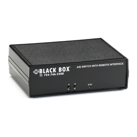
A/B SWITCH WITH REMOTE INTERFACE
Page 2 of 22
FEDERAL COMMUNICATIONS COMMISSION
AND INDUSTRY CANADA
RADIO FREQUENCY INTERFERENCE STATEMENTS
This equipment generates, uses, and can radiate radio-frequency energy, and if not installed and used properly, that
is, in strict accordance with the manufacturer’s instructions, may cause interference to radio communication It has
been tested and found to comply with the limits for a Class A computing device in accordance with the
specifications in Subpart B of Part 15 of FCC rules, which are designed to provide reasonable protection against
such interference when the equipment is operated in a commercial environment Operation of this equipment in a
residential area is likely to cause interference, in which case the user at his own expense will be required to take
whatever measures may be necessary to correct the interference
Changes or modifications not expressly approved by the party responsible for compliance could void the user’s
authority to operate the equipment
This digital apparatus does not exceed the Class A limits for radio noise emission from digital apparatus set out in
the Radio Interference Regulation of Industry Canada
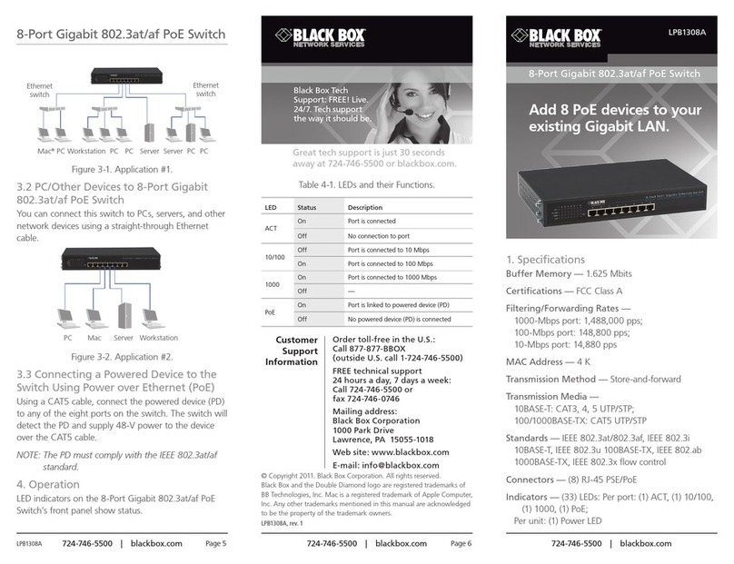
1. Specific tions
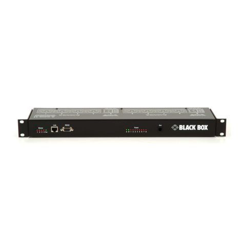
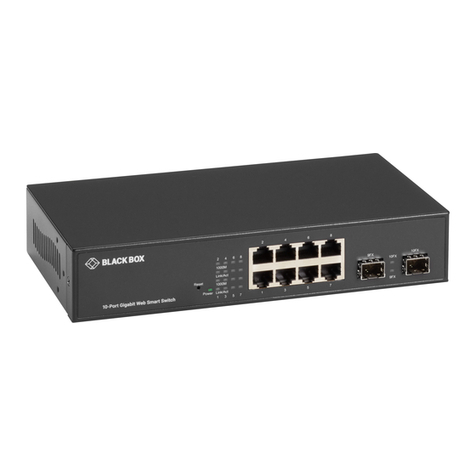
Connectors:
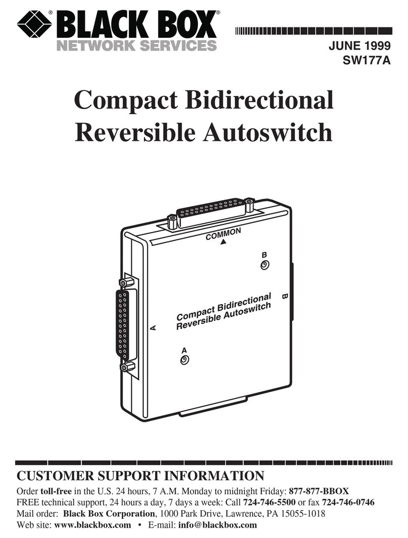
A/B Switch Ports:
(3) RJ45 CAT6, or
(3) DB9F, or (3) ST, SC, FC or LC (depending on model)
Ethernet Control Port:
(1) RJ45 10Base-T port for remote control interface (E/N controllable
models only)
Serial Control Port: Female DB9
(serial controllable
models only)
Remote Control/Status Port: (1) 6 Position Pluggable Phoenix Terminal Block
Power: (1) 3 5-mm power input
Indic tors:
Switch position LEDs: (2) position A and position B
Command status LED: (1) command executing
Switches: (2) momentary push button switches for A/B switch port control
Power: 100-240VAC, 50/60-Hz wall mount supply, 12VDC output
Power Consumption (typical):
Model 12 VDC load 120 VAC load
Base Model without Serial Control 20 mA DC 15 mA (AC RMS)
Serial Control Model 40 mA DC 20 mA (AC RMS)
Ethernet and Serial Control Model 110 mA DC 35 mA (AC RMS)
Switching Load (CAT6) Additional 65 mA DC Additional 20 mA (AC RMS)
Switching Load (DB9) Additional 80 mA DC Additional 20 mA (AC RMS)
Switching Load (Multimode Fiber) Additional 95 mA DC Additional 25 mA (AC RMS)
Switching Load (Singlemode Fiber) Additional 75 mA DC Additional 20 mA (AC RMS)
On latching units, the switching load is applied for approximately 0 15 seconds during switching On non-latching units, the
switching load is constant in the B state, and therefore must be added to the steady state load
Remote Control Inputs: External dry contact not to exceed 100 ohms resistance including cable
Output St tus Rel y Cont ct R ting: 30 VDC, 1A maximum (resistive)
D t R tes: switch ports on all models are transparent to data rates, formats & protocols
RJ45 CAT6 models support 10/100/1000 and 10G Ethernet
DB9 models support data rates in excess of 10 Mbps
Fiber Optic models support data rates in excess of 10Gbps

