BOREAL LASER GasFinder FCr User manual

GasFinder FCr
BOREAL LASER INC.
Operation Manual
Boreal Laser Inc. GasFinderFCr Operation Manual July 17th 2017
GasFinderFCr
Part No. NDC-200005-D
Menu ver. 1.10.c
12846 146 Street NW • Edmonton, Alberta • CANADA • T5L 2H7
Phone: +1 780 488 5173 • Fax: +1 780 488 0780 • www.boreal-laser.com
OP1
Remote Head
OP3
Remote Head
V1 Duct Probe
Retros

ii
Boreal Laser Inc. GasFinderFCr Operation Manual July 17th 2017
Written by Boreal Laser Inc.
Rev. #1 November 2006
Rev. #2 June 2007 Sec. 5, 9 Menu (ver. 0c43)
Rev. #3 June 2009 All Menu (ver. 1d03)
Rev. #4 December 2010 All Menu (ver. 1.06.a)
NDC-200005 January 2011 All Menu ver. (1.06.a)
NDC-200005-A March 2011 Sect 1,9 Menu ver. (1.06.a)
NDC-200005-B January 2012 Title Pages Menu ver. (1.08.c)
NDC-200005-B August 2013 All Menu ver. (1.10.c)
NDC-200005-C July 17th 2017 All Menu ver. (1.10.c)
BOREAL LASER INC.
Publications by Boreal Laser Inc.
Operation Manuals:
GasFinder2 NDC-200023-A
GasFinderFC NDC-200004-B
GasFinderFCr NDC-200005-c
GasFinderAB NDC-200006-B
GasFinderMC NDC-200010-C
GasFinderPT NDC-200021-B
GasFinder2 for
Multiple Path Monitoring NDC-200025-A
User Manuals:
GasViewOP NDC-200022-B
GasViewMC NDC-200013-B
GasMap NDC-200007-A
Accessory Manuals:
4-20mA Module NDC-200014-A
RF Barrier Module NDC-200027-A
DCR Module NDC-200016-A
Diagnostic and
Troubleshooting Kit NDC-200026
Copyright 2013 Boreal Laser Inc. All rights reserved.
Reproduction in any manner without the written permission of Boreal Laser Inc. is strictly forbidden.
Boreal Laser Inc. makes no representations or warranties with respect to the contents of this document.
Boreal Laser Inc. assumes no responsibility for errors or omissions or any damages resulting from the use of the
information contained in this document. Information in this document is subject to change without notice.
Ph.+1 780 488 5173 Fax +1 780 488 0780
E-mail <support@boreal-laser.com>

iii
Boreal Laser Inc. GasFinderFCr Operation Manual July 17th 2017
Contents
Section 1. System Description........................................................................................ 1.1
Specifications............................................................................................................... 1.3
GasFinderFCr................................................................................................................1.3
OP1 Open Path Transceiver (Remote Head)........................................................................ 1.3
OP3 Open Path Transceiver (Remote Head)........................................................................ 1.3
V1 Duct Tranceiver (Duct Probe)........................................................................................... 1.3
Certification...............................................................................................................1.4
Labels .......................................................................................................................1.4
Safety Concerns............................................................................................................1.4
Section 2. Pre-Installation Checks..................................................................................2.1
GasFinderFCr, Remote Heads, Retroreflectors Duct Probes........................................2.1
Tools and Equipment............................................................................................................. 2.2
Equipment Check..........................................................................................................2.2
Section 3. Installation....................................................................................................... 3.1
GasFinderFCr.............................................................................................................. 3.1
Retroreflectors ............................................................................................................. 3.1
Light Values ................................................................................................................. 3.1
Condensation............................................................................................................... 3.3
Transceivers (Remote Heads)..................................................................................... 3.4
OP1 Remote Head........................................................................................................3.4
OP3 Remote Head........................................................................................................3.5
Optical Alignment...........................................................................................................3.7
Adjusting the Aiming Scope...........................................................................................3.8
V1 Duct probe................................................................................................................3.9
Cable Connections..................................................................................................... 3.10
Fibreoptic.....................................................................................................................3.10
Coaxial.........................................................................................................................3.11
Data.............................................................................................................................3.12
Power ..........................................................................................................................3.12
Section 4. Data Input/Output........................................................................................... 4.1
DB15 Connector .......................................................................................................... 4.1
Serial Communications................................................................................................ 4.2
Data String Specification.............................................................................................. 4.2
Debug String Specification........................................................................................... 4.3
Date and Time fields......................................................................................................4.3
Data Transmission.........................................................................................................4.4
Downloading Data........................................................................................................ 4.5
HyperTerminal ..............................................................................................................4.5
4-20mA..........................................................................................................................4.6
BOREAL LASER INC.
BOREAL LASER INC.
GasFinderFCr
OPERATION MANUAL

iv
Boreal Laser Inc. GasFinderFCr Operation Manual July 17th 2017
Section 5. Operating Instructions................................................................................... 5.1
Start Up........................................................................................................................ 5.1
Menu Details................................................................................................................ 5.3
Main Menus..................................................................................................................5.3
System Menus .............................................................................................................5.6
Password Protected Menus..........................................................................................5.8
Section 6. Maintenance....................................................................................................6.1
GasFinderFCr.............................................................................................................. 6.1
Remote Heads & Duct Probes.....................................................................................6.1
Cables.......................................................................................................................... 6.1
Retroreflectors ............................................................................................................. 6.2
Section 7. Troubleshooting ............................................................................................. 7.1
Array Transfers ............................................................................................................ 7.3
Stability of Support Structures ..................................................................................... 7.4
Types of Supports..........................................................................................................7.5
Alignment Procedures for a Moving Building.................................................................7.6
Centering Cross Hairs...................................................................................................7.7
Section 8. The Basics of Laser Gas Detection .............................................................. 8.1
Tuneable Diode Laser ...................................................................................................8.1
Absorption Lines...........................................................................................................8.1
Gas Detection with a Laser ...........................................................................................8.2
Retroreflectors...............................................................................................................8.3
Glossary of Common Terms and Abbreviations. ...........................................................8.4
Section 9. Appendices .................................................................................................... 9.1
Appendix A — Menu Structure..................................................................................... 9.1
Appendix B — Status Codes ....................................................................................... 9.3
Appendix C — Explanation of ppmm........................................................................... 9.4
Appendix D — Explanation of R2 ................................................................................ 9.5
Appendix E — Conversion from ppm to mg/nm3......................................................... 9.7
Appendix F — Log to Memory.................................................................................... .9.8
Appendix G — Calibration ......................................................................................... 9.10
Appendix H — Pre-Ship Settings................................................................................9.11
Appendix I — Accessories....................................................................................... 9.12
Appendix J — Cable Compensation......................................................................... 9.13
Appendix K — 2-Way Serial Communication............................................................ 9.14
Section 10. Drawings ..................................................................................................... 10.1
1. GasFinderFCr Interconnection – JB0512FC-A....................................................10.1
2. GasFinderFCr Dimensions – JB0125MC-A...................................................10.2
3. OP1 Remote Head Dimensions – BOR 02110-J..................................................10.3
4. OP3 Remote Head Dimensions – JB 0930 RH-B ................................................10.4
5. V1 Duct Probe General – DP-D-V1-001..................................................10.5
6. V1 Duct Probe Dimensions – DP-D-V1-002..................................................10.6
7. V1 Duct Probe Connections – DP-D-V1-003..................................................10.7
8. OP3 SS Enclosure Dimensions – BOR 02910....................................................10.8
9. OP3 SS Tilting Joint Dimensions – BOR 02915....................................................10.9
v
Boreal Laser Inc. GasFinderFCr Operation Manual July 17th 2017
Before operating the system, please read this manual fully to obtain the best results from your
product. The lightning flash with arrowhead inside the triangle, is intended to alert the user to
the presence of un-insulated dangerous voltage within the products enclosure that may be of
sufficient magnitude to constitute a risk of electrical shock to persons.
CAUTION: TO PREVENT THE RISK OF ELECTRIC SHOCK, DO NOT REMOVE COVER (OR BACK).
NO USER-SERVICEABLE PARTS INSIDE. REFER SERVICING TO QUALIFIED SERVICE PERSONNEL
ONLY.
SAFETY INSTRUCTION:
Please read all the instructions herein.
Please heed all safety warnings. Please retain this manual for future reference.
Please install in accordance with these instructions.
WARNING
TO REDUCE THE RISK OF ELECTRIC SHOCK:
Do to expose this equipment to rain or moisture.• Do not use the unit near water, and do not immerse in any liquid or pour any liquid on the unit.• Servicing is required when the unit has been damaged in any way, such as the power-supply cord• or plug is damaged, liquid has been spilled or objects have fallen into the unit, the unit has been
exposed to rain or moisture, does not operate normally, or has been dropped.
Refer all servicing to qualified personnel only. The unit contains no user servicable parts.•
Note that if the equipment is used in a manner not specified in the manual,
the protection provided by the equipment may be impaired.
Removal of the equipment cover will void any warranty.
Disclaimer
Boreal Laser Inc. assumes no liability or responsibility for issues or harm resulting from the
use of this equipment.

vi
Boreal Laser Inc. GasFinderFCr Operation Manual July 17th 2017
V1 Duct Probe GasFinderFCr
mounted in cabinet
2 OP3 Remote Heads
in stainless steel enclosures
2 OP1 Remote Heads
OP1 Remote Head
OP3 Remote Head

vii
Boreal Laser Inc. GasFinderFCr Operation Manual July 17th 2017
MANUFACTURER’S WARRANTY
COMMITMENT TO CUSTOMER SATISFACTION
Boreal Laser is committed to working closely with customers to define gas detection solutions that
Boreal Laser can deliver and that meet customer requirements. However, very rarely, unforeseen
circumstances relating to a specific installation may prevent a Boreal Laser solution from meeting all
customer expectations.
Boreal Laser will make every reasonable effort to work with the customer to modify an installation to
meet requirements for up to 12 months after installation. Should these efforts fail, Boreal Laser will
negotiate with the client for the removal and return of Boreal supplied equipment. Refunds will be
arranged on a case-by-case basis depending upon the specific circumstances.As a guideline, Boreal
will provide a full refund less 10% re-stocking charge on Boreal Laser manufactured items. Refunds
will typically not apply to the following: installation specific items such as cabling and mechanical
mounting structures; non-recurring engineering charges associated with the specific project; technical
support expenses (labor and travel related costs) invoiced during the course of the project.
STANDARD WARRANTY
Boreal Laser provides a standard warranty with all Boreal Laser manufactured GasFinder2,
GasFinderFC, GasFinderMC, GasFinderAB and GasFinderPT laser gas detector products. The
warrantycovers theGasFinder laser analyzersplus Boreal Lasermanufactured itemssupplied with the
GasFinder laser analyzers such as: battery packs; power supplies; x-y mounts; open path transceiver
heads; duct probes; external gas sample response cells; 4-20mA modules; RF Barrier modules; dry
contact relay modules. The standard warranty does not cover items manufactured by third parties
and supplied as components of a system, such as: cables; reflector elements; enclosures; scanning
mounts; meteorological instruments; etc.
For items covered by the standard warranty, Boreal Laser guarantees that, during the first 12 months
following delivery, there will be no charges for parts or service required to correct:
• Equipment breakdowns
• Equipment malfunctioning
• Repeated or recurring faults or errors in the system.
Instrument shipping and/or travel expenses for on-site service will be charged at cost.
This warranty does not apply to situations whereby system performance has been compromised as a
result of customer negligence or abuse or damage resulting from natural disasters.
Boreal Laser provides software upgrades and unlimited telephone and e-mail support free of charge
for the lifetime of an installation. Boreal Laser software is provided ‘As Is’ without any express or
implied warranty of any kind. Boreal Laser is not liable for any damages (including, without limitation,
lost profits, business interruption, or lost information) arising out of use of or inability to use Boreal
Laser software products.

viii
Boreal Laser Inc. GasFinderFCr Operation Manual July 17th 2017
ENHANCED WARRANTY
Boreal Laser can quote Enhanced Warranty on a project specific basis to include some or all of the
following:
• Include all non Boreal Laser manufactured items supplied on a specific job.
• Extended warranty if a delay is expected from the time of delivery to the time of
installation and commissioning.
• Include a specified number of site visits during the warranty period - highly
recommended for development projects.
• Extended warranty on GasFinder systems beyond the standard 12 month period.
PROCEDURES FOR RETURNING A UNIT TO BOREAL LASER
Contact Boreal Laser Inc. at support@boreal-laser.com or +1 (780) 488-5173 to request a Return
MaterialAuthorization (RMA)number and any other specificshipping details; please provide extended
warranty registration number if applicable.
Important Instructions for Return Shipments:
Send all returns with RMA# clearly marked on outside of container and/or shipping label to:
Boreal Laser Inc.
Service Department - [RMA #xxxx]
12846 – 146 Street NW
Edmonton AB T5L 2H7
CANADA
Indicate ‘Equipment being returned to manufacturer for service’ and indicate a value for customs
of $500.

1.1
Boreal Laser Inc. GasFinderFCr Operation Manual — System Description July 17th 2017
Boreal Laser’s patented (US Patent 5,637,872) TDL (Tunable Diode Laser) fibre coupled
monitor measures gas concentration over an open path. The monitoring system consists
of a rack mounted integrated transmitter/receiver known as the Central Control Unit (CCU),
an open path transceiver head or duct probe, and a remote, passive retroreflector array. A
fibreopticcable connects theCCU to thetransceiver head orduct probe.Atwo-axisinstrument
mount and an aiming scope or red aiming laser are used to align the remote head with the
retroreflector array. Thr returning laser signal is detected by a photo diode in the remote head
or duct probe and sent back to the CCU via a coaxial cable.
The GasFinderFCr is a rack mounted unit 3U high and fits in a stanrd 19” rack enclosure.
It houses the laser diode source and microcomputer subsystems and has connectors for
120/240V power input, and data I/O. The remote head or probe is connected with fibreoptic
and coaxial cables.Aschematic representation of the GasFinderFCr system is shown below
in figure 1:
The laser signal from the GasFinderFCr is sent through a fibreoptic cable to the remote head
or duct probe where it is emitted and propagates through the atmosphere to the retroreflector.
It then returns to the cell where it is focused on to a photo diode detector. The detector
converts it to an electrical signal which travels through a coaxial cable to the electronics in the
GasFinderFCr. A portion of the laser beam is passed through an on board reference cell to
provide a continuous calibration check. These two optical signals are converted into electrical
waveforms which the computer processes to determine the actual concentration of gas along
the optical path. The computed gas concentration is then displayed on the rear panel of the
instrument, and can be transmitted to a computer where the data can be collected, stored,
and graphically displayed. For industrial applications a 4-20mA output is also available.
A software program, GasViewOP is available which runs on the computer and can be used
to alter some of the parameters on the GasFinderFCr
Fig. 1 Schematic representation of GasFinderFCr
Section 1. System Description
Control
Electronics
120/240 Vac input
Data I/O
Keypad
Display
GasFinderFCr
Laser
Diode
Detector
Computer
Calibration
Reference
Cell
Signal
Processing
&
Display
Remote
Retro-reflector
Remote
Retroreflector
Duct Probe
Aiming Scope
Remote
Head

1.2
Boreal Laser Inc. GasFinderFCr Operation Manual — System Description July 17th 2017
Array containing 21
reflectors
Enclosure containing 4
corner cube retro reflectors
and a thermostatically
controlled heater
Retro Tapes
Remote Head Duct Probe
The three main parts of the equipment are:
GasFinderFCr, or CCU• Open Path Transceivers• or Remote Heads and Duct Probes
Remote Reflectors, or Retros•
GasFinderFCr• unit contains the laser diode and electronics and
ismounted in acabinetin aprotectedarea at afixedlocation.The
frontpanel containsa Liquid CrystalDisplay (LCD)which displays thegas concentrationin
ppm/ppmm with an R2or Light Value indicator. When required, the display can also show
the system parameters which are accessed using a key pad. The rear panel contains the
powersupplyconnector,I/O connectorsand fibreopticand coaxial connectors.Specifications
of the GasFinderFCr are given on page 1.3. The unit is configured by entering values
using a key pad on the front panel or with a computer using GasViewOP. These values
are described in the Menu Structure which contains three subsections:
Main Menu contains items such as path lengths, units, memory, etc.
Maintenance Menu contains arrays, real time clock, baud rates, etc.
Password Protected Menu contains calibration values.
Details of the menus are given on pages 5.3 to 5.6 and a flow diagram is shown inAppendixA.
Heads• and Probes are passive units and require no power.
Retroreflectors• are passive units and reflect the laser signal back to the Heads or Probes. For
short distances (up to 30m), reflective tape can be used. For greater distances corner
cube or IMOS retroreflectors should be used. The corner cube retroreflectors allow for
alignment tolerance (i.e., they reflect the light straight back to source independent of the
angleofthe reflector).Thesealedenclosures can beprovidedwith hoods, desiccantpacks,
and in some cases heaters to reduce the effect of rain, condensation or frost. The type of
reflector used will depend on the path length, atmospheric conditions such as dust or fog,
and the type of laser.
Details of the reflectors are given on page 3.2.
GasFinderFCr

1.3
Boreal Laser Inc. GasFinderFCr Operation Manual — System Description July 17th 2017
Specifications
GasFinderFCr
Weight 8.5kg (18.7 lb)
Dimensions (L x W x H) 374 x 446 x 132mm (14.7 x 17.6 x 5.2ins) See drawing Section 10.
Power Requirements 1A @ 120/240Vac
Operating Temperature Range 10C to +30C
Scan Rate 1 sample / sec
Display 2 x 20 character Liquid Crystal Display
Laser Type Semiconductor
Laser Output 20mW
Data Output RS232, serial data, CSV.
Optional 4 - 20mA current loop
Baud Rate .3 / 1..2 / 2.4 / 4.8 / 9.6 / 19.2 / 38.4 / 57.6 / 115.2 / 230.4 kbps.
Cable, Fibre-optic 9/125 micron single mode with FC/APC connectors
Cable, Coaxial Belden 9880 Ethernet Cable
Patch cord Belden 89907
Accessories
OP1 Open Path Transceiver (Remote Head)
Weight 3.0kg (6.6 lb)
Dimensions (L x W x H) 315 x 106 x 180mm (12.4 x 4.2 x 7.1ins)
Power Requirements Nil
Alignment Open sights, visual laser accessory
OP3 Open Path Transceiver (Remote Head)
Weight 2.0kg (4.4 lb)
Dimensions (L x Diam) 310 x 105mm (12.2 x 4.1ins)
Power Requirements Nil
Alignment 3/9 x 40 aiming ‘scope, visual laser accessory
OP3 Open Path Transceiver (Remote Head) with Stainless Steel Enclosure
Weight 14.1 kg (31.0 lbs)
Dimensions (L x W x H) 761 x 250 x 385 mm (30.0 x 9.8 x 15.2 inches)
V1 Duct Transceiver (Duct Probe)
Weight 7.5kg (16.5 lb)
Dimensions (L x Diam) 525mm x 75mm flange (20.7 x 3ins)
Purge Air 1bar @ 10 l/m (depending on dust loading)
Alignment Visual laser accessory
V1 Duct Probe Reflector
Various
1.4
Boreal Laser Inc. GasFinderFCr Operation Manual — System Description July 17th 2017
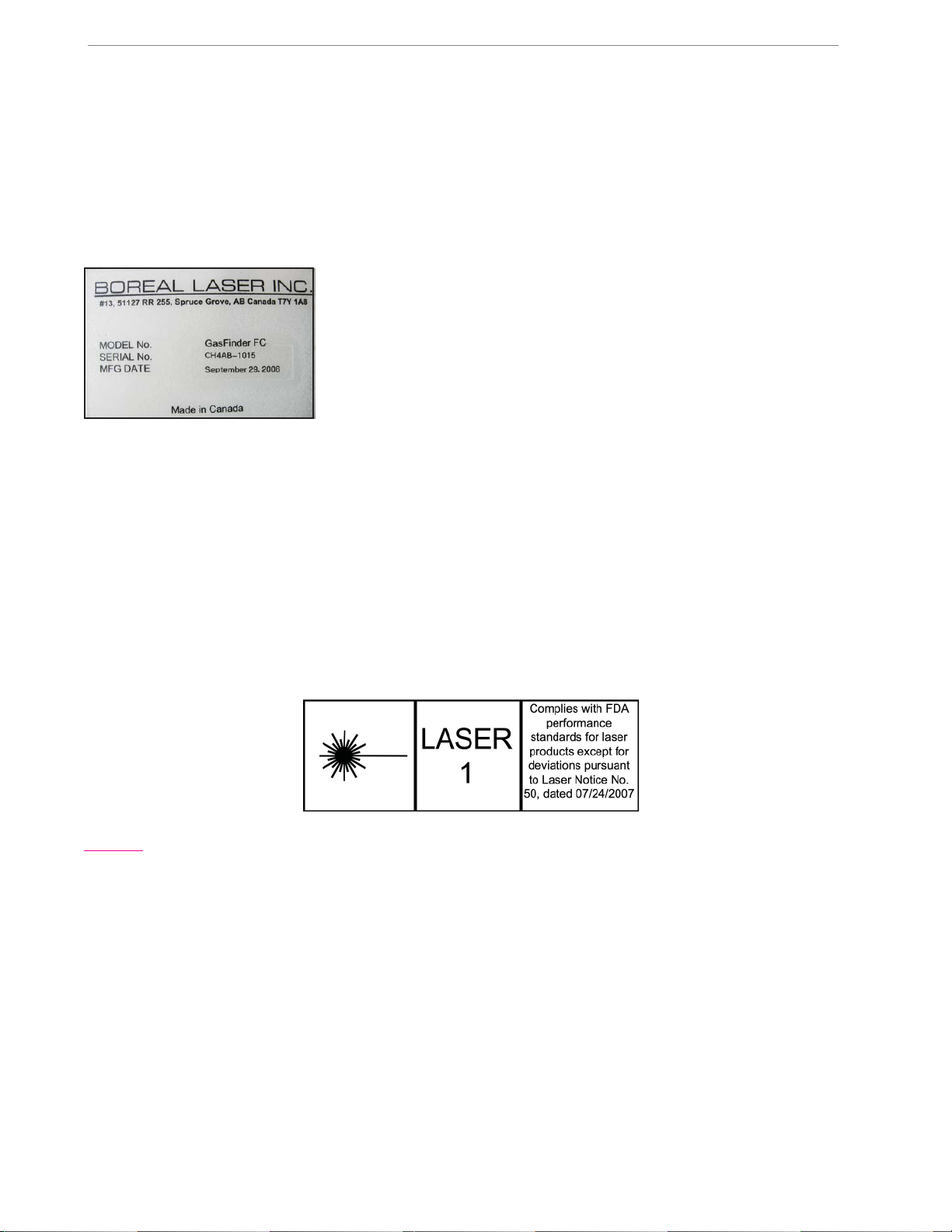
Labels
Thislabelisaffixedtotherear
of the GasFinderFCr and
gives the instrument serial
number and manufacturing
date.
Certification
OP3 Head CSA Class 1, Division 1, Groups A, B, C and D
CSA Encl. Type 3R Exia
CENELEC EEx ia IIC T4 LCIE SYST 01.E6049 X
Safety Concerns
Boreal Laser’s GasFinderFCr contains an invisible (infrared) laser source.
The infrared laser and red aiming lasers conform to Class 1 as per IEC 60825-1 and are eye-
safe. They do not require the use of protective eye wear, protective equipment, or outdoor
control measures. There is no optical ignition hazard presented by lasers of this type.
There are no user serviceable components contained in apparatus, all units must be returned
to factory for repair.
Caution: — The infrared laser output from the GasFinderFCr has very low power(conforms to Class
1 as per IEC 60825-1) and will not damage eye tissue. However, it is the recommendation of Boreal
Laser Inc. that, as withANY LASER SYSTEM, the user/operator should avoid staring directly into the
output aperture of the instrument.
Note that the laser beam is infra-red and is not visible to the eye.
The GasFinderFCr transceiver unit is not intrinsically safe and is normally located away from
a hazardous area.
The retroreflectors are intrinsically safe and can be used in hazardous areas. In hazardous
areas, where heaters are required to prevent condensation, they should be of a suitable type.

2.1
Boreal Laser Inc. GasFinderFCr Operation Manual — Pre Installation July 17th 2017
Section 2. Pre-Installation Checks
GasFinderFCr
A site survey should be undertaken to check the following points:
Temperature Limits:• the GasFinderFCr cabinet should be
located in a temperature regulated (100C to 300C) room in an
area which minimises the length of cable runs (limit the length to
750m). A compromise for the location usually has to be found,
but if no suitable room is available, an air-conditioned cabinet
can be used.
Power Supply:• 110/220V 1A power should be available in the cabinet with spare 110V
outlets if possible. A UPS may be desirable.
Accessibility:• safe access to the front and rear of the GasFinderFCr should be possible
with a hinged cabinet mount.
Size:• theGasFinderFCr is 3U highand thecabinet should bebig enoughto accommodate
all the required modules, splice boxes and cable terminations.
Cables:• cable trays or conduit should be used to support the coaxial and fibreoptic cable
between the GasFinderFCr and the Remote Head or Duct Probe. Do not run cables
alongside power cables, especially cables used for Variable Frequency Drives.
Remote Heads
Remote Head locations should be chosen with regard to visibility and
limiting paths to 500m for OP3 Remote Heads, and be in areas that are
safely accessible for installation and maintenance. Limit cable runs to
750m or an appropriate distance to pull the cable. Dusty locations are to
be avoided if possible. The Remote Head mounting can withstand small
vibrations and some translational motion but is extremely sensitive to
rotational movement. The mounting must be rigid and well braced. Pre-
terminated cables can be brought directly into the enclosure, otherwise
itis necessary touse asplice box close(1m) tooneside andrun a patch
cord to the Remote Head. Mounting locations outside where sun can
strike directly on the mount structure may require insulation to prevent
movement due to differential heating.
Retroreflectors
Retroreflector locations should be chosen to limit paths to the suitability of the remote head
and be in areas that are safely accessible for cleaning when necessary.
Dusty locations should be avoided if possible. Steam may pose a
problem if it is dense and consistently crosses the path.
If the location is outside and the climate is humid, a rain hood and a
heated enclosure may be necessary to prevent condensation on the
window. This usually requires an outlet close by to supply power to a
heater.
The reflector mounting can tolerate small vibrations and movement, but
OP3 Head
2 OP3 heads in
SS enclosures
GasFinderFCr
in cabinet
4 Retroreflectors
with heater

2.2
Boreal Laser Inc. GasFinderFCr Operation Manual — Pre Installation July 17th 2017
the reflector enclosure should be attached with the front window perpendicular to the path.
There should be no obstructions in the path between the retroreflector and the head.
Duct Probes
Alignment is made easier if the flanges for the Duct Probes are
welded perpendicular to the path axis. Clean air up to 10 litres/
min, controlled with a regulator, should be provided for purging the
Duct Probe and retro windows. Ducts with a heavy dust load, may
require a higher flow rate.
Tools
Required:
Site-specific personal protective equipment• Permanent marker or pen• Set of assorted cable ties• Socket wrench set• Small adjustable “crescent” wrench• Small vise grips• Phillips, Robertson and Flat Head screwdrivers• Allen Keys (imperial and metric)• Coaxial-cable termination tool• (Amphenol crimper:ARF1118 with CTL-3 jaws. 0.100D and 0.429D.)
Wire cutters, wire stripper, linesman’s scissors, pliers• Knife• Duct tape• Electrical tape and self-amalgamating tape• Label maker or cable markers• Silicone sealant RTV3145• Twist drill set and step-bit or hole-saw selection• Small multimeter• Ladder and/or man-lift (as appropriate)• If pre-terminated cables are not used then a cable splicer is required capable of making•
FC/APC connections.
Optional/Recommended:
Two-way radios (if per• mitted)
Equipment Check
Verify that all the equipment on the order sheet has
arrived complete and in good condition.Any damage
due to shipping should be reported immediately and
steps taken to obtain replacement parts.
Order ready for shipment
2 Duct Probes with
Purge Air and Splice Box

3.1
Boreal Laser Inc. GasFinderFCr Operation Manual — Installation July 17th 2017
Section 3. Installation
Safety IssuesCaution : — The laser output from the GasFinderFC has very low power
(conforms to Class 1 as per IEC 60825-1) and will not damage eye tissue.
However, it is the recommendation of Boreal Laser Inc. that, as withANY LASER
SYSTEM,theuser/operatorshouldavoidstaringdirectlyintotheoutputapertureof
the instrument. Note that the laser beam is infra-red and is not visible to the eye.
Tools Required: Electrician’s hand tools, set of Allen keys.
The Boreal Laser Inc. fibreoptic test kit is recommended.
GasfinderFCr
The GasFinderFCr fits into a cabinet with
a standard 19” (485mm) rack and is 3U
(132mm) high. If the cabinet is mounted to
a wall or access to the rear is difficult then
a hinged cabinet is required. This allows
the cabinet to swing outwards and makes
the cable connections much easier to install.
Retroreflectors
The retroreflector is a vital part of the system and choosing the correct one is necessary for the
correct operation of the system. Refer to page 3.2 for details on choosing a reflector. For short
paths where reflective tape is used, the tape can be attached to the back of an enclosure which
is fitted to a tripod or placed on a wall in any convenient location. The angle of the tape can be
adjusted to give an adequate signal return provided this does not degrade the R2value.
Whereretro• reflectorsare usedon longer paths,these maybe mounted inan enclosure
on a tripod, or the enclosure placed in any convenient location.
Purge air may be required for retros used in ducts.•
Where long paths are measured in metal buildings, the remote head may go out of• alignment as a result of solar heating deforming the structure. The preferred solution
is to use multiple reflectors. See pge 7.7
The• GasFinderFCr does not require any changes when different path lengths are
measured unless ppm values are needed, in which case the distance must be set and
an appropriate reflector used.
Light Values
Thetype ofreflector usedwill depend on the pathlength, atmosphericconditions suchas dust
or fog, and the type of laser. When choosing a reflector, the prime concern should be to keep
the returning light level value between the preferred values of 4,000 and 8,000. The range
of the value is between 1000 and 16,368. Below 1000 the display will indicate “Low Light”.
There is no indication that the returning light has exceeded 16,368. When this happens the
receiver saturates and the displayed light value could read very low (<200). In this situation
the gas concentration readings will be in error and it is also possible to cause damage to the
optical components. The light value can be adjusted with the use of different reflectors.
Note: Care should be taken to ensure that the returning light does not exceed 14,000.
GasFinderFCr
in enclosure
Cable connections at rear
of GasFinderFCr
3.2
Boreal Laser Inc. GasFinderFCr Operation Manual — Installation July 17th 2017
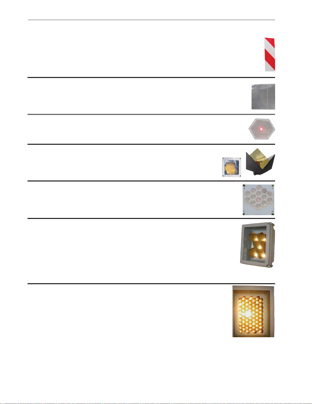
Reflector types Path Length
Up to 76
63mm Retros 600–750m
Description
Grey Tape comes in sheets 200 x 300mm. It is
adhesive backed and can easily be attached to any
smooth, dry surface. It is often stuck to the back of a
retro enclosure.
Grey Tape 5–40m
The tape comes in 16m rolls x 50mm wide. The tape is
divided into red and silver bands and each have different
reflective properties. The tape is adhesive backed and can
easily be attached to any smooth, dry surface. It is often
stuck to the back or side of a retro enclosure.
Red/White
Tape 1–5m
Thesearemulti-facetedIMOS46mm hexagons.They
can be fitted together to make up a large composite
array.
IMOS plastic
46mm Retro 30–100m
The IMOS array shown is made from 14 single
hexagonal retros. They are normaly mounted on
a back plate which is placed in a stainless steel or
FRP enclosure.
IMOS array 50--300m
76 retros are probably the maximum number
that can be economically used as the cost
becomes prohibitive as the number of retros
increases. At path lengths approaching 750m,
maintaining the correct alignment becomes
difficult.
These retros are enclosed in a PVC, RPF or
stainless steel enclosure. The number of retros
will depend on the type of gas being measured,
the path length and atmospheric conditions. The
window is normally Lexan but can be changed to
a special glass when measuring some gases. For
outsideuserainhoods and heatedenclosuresare
recommended to prevent condensation.
Up to 6
63mm Retros 75m – 400m
This is a gold plated hexagonal retro. It is normally
housedinaplastic or steelboxwithaLexan
window. They can also be fitted together to
make up a large composite array.
63mm Retro 75 – 150m
The enclosures will vary in size depending on the number of retros and if internal heating is
required. Window materials will depend on the site conditions and the gas to be measured.
Lexan is normally supplied but window glass, boro-silicate and sapphire are used under
specific circumstances. Contact Boreal Laser Inc. for more information.

3.3
Boreal Laser Inc. GasFinderFCr Operation Manual — Installation July 17th 2017
Condensation
Condensationonthesurfaceofthewindowiscausedbythewindowtemperature
falling below the dew point. This may occur in areas of high humidity or large
temperatures differences between day and night. The enclosures are well
sealed but condensation can sometimes occur on the inside of the window.
Condensation can usually be controlled by the following measures:
Fasten a cover or rain hood over the enclosure to shield the• window from the effect of radiation cooling at night. This also
prevents rain from striking the window.
Use a desiccant pack inside the enclosure. This will only prevent• condensation on the inside.
Place a heater in the enclosure. The heater can be 12W to 50W• depending on the size of the enclosure and the conditions of
operationand iscontrolled by athermostat toprevent overheating.
The heater raises the temperature of the enclosure and prevents
condensation forming either on the inside or the outside of the
window. To minimise heat loss the enclosure is insulated. This
optionrequirespowertobesuppliedandthereareheatersavailable
for use in hazardous areas.
SS Enclosures with
Heaters and Rain Hoods
4 retros
4 retros
heater
heater
thermostat
thermostat
4 retros and heater in
insulated enclosure
Radiation Shield

3.4
Boreal Laser Inc. GasFinderFCr Operation Manual — Installation July 17th 2017
Transceivers (Remote Heads, Duct Probes)
There are various types of transceivers to which the GasFinderFCr can be connected:
- OP1
- OP3
- V1
OP1 Transceiver (Remote Head)
This Remote Head is designed to be used for path lengths up to
50m. It has a weather resistant stainless steel assembly and has an
adjustable base. It is mounted with a single 12mm bolt and locking
screws if required.
Mount the Remote Head directly to a galvanised steel plate• at least 100mm square. Rotate the unit so that the head is aligned with the reflector.
Tighten the 12mm bolt.
Remove the 8 screws from the rear plate.•
Connectavisible laser tothefibreopticlaserconnector• at the rear of the unit.Align the Remote Head until the
red dot appears on the reflector.
Connect the fibreoptic and coaxial cables to the rear• connectors and to the GasFinderFCr and switch on.
Make a final alignment adjustment by maximising the• light return value. Tighten all the locking screws and
secure the cables, making sure that the weight of the
cables does not alter the alignment of the Remote
Head.
OP1 Head
2 OP1 Heads
Reflector for a 100mm path
8 fastening screws
Co-ax connector
Laser connector
Horizontal
alignment screw
Vertical
alignment screw
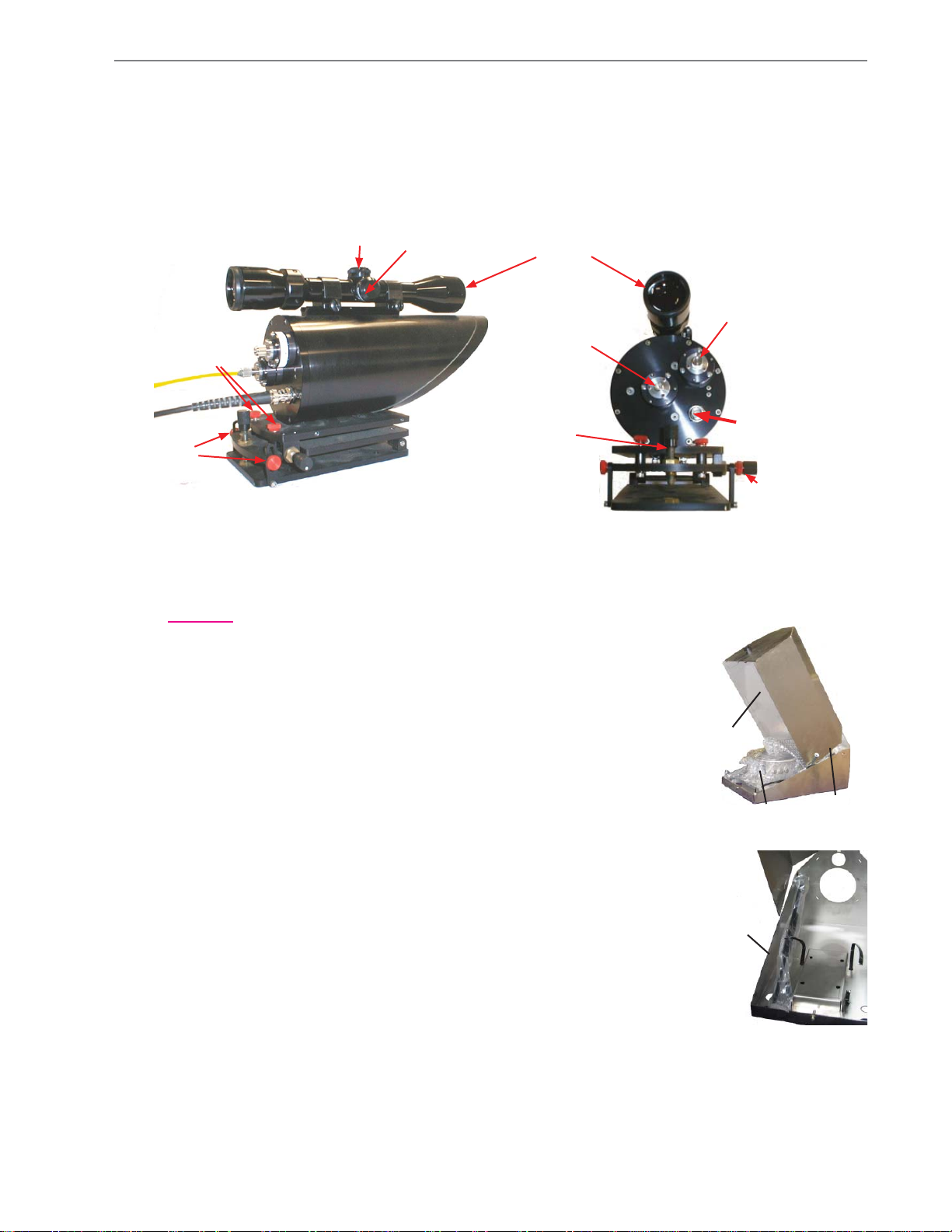
3.5
Boreal Laser Inc. GasFinderFCr Operation Manual — Installation July 17th 2017
Red aiming
laser input
I.R. laser input
Aiming scope
Vertical
locking screws
Cross hair adjustment
screw covers
Horizontal
locking screws
Vertical
alignment screw
1 turn - 2.0 mrad
Coaxial output
Horizontal
alignment screw
1 turn - 2.6 mrad
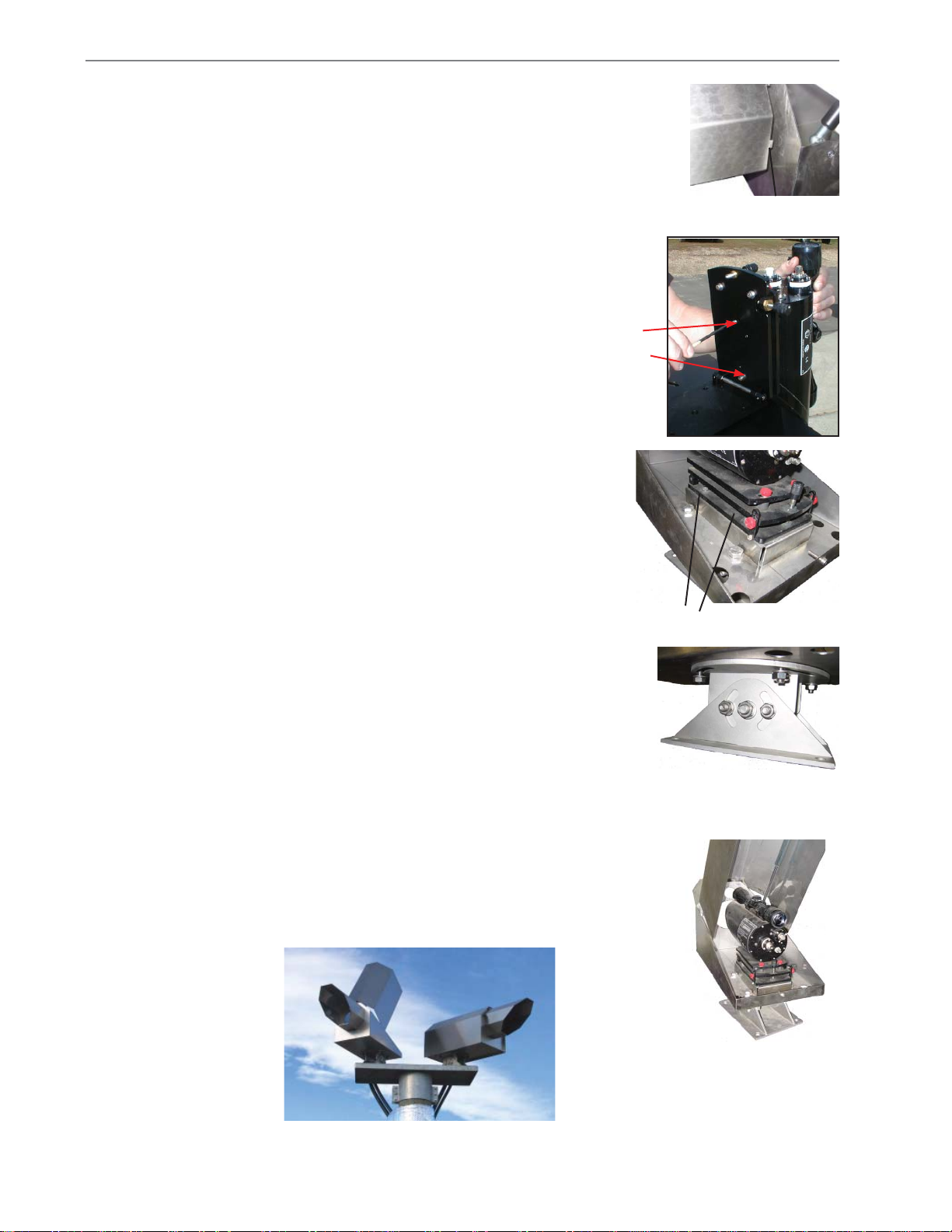
Installing the Mount and the Stainless Steel Enclosure
Caution. care should be taken not to get the fingers trapped between the cover
and the sides of the base, especially before the shocks have been
connected.
Remove the enclosure from the packing case, open the cover• and remove the base and the nose from inside.
There is a tubular spring loaded support laying at either side of the• base. Remove the plastic bag and attach the front of the support
to the front of the cover.
Attach the nose to the front of the base by inserting the tabs on the nose into the slots•
OP3 Open Path Transceiver (Remote Head)
This Remote Head is designed to be used for path lengths up to 750m. It can be fitted in an
enclosure and uses an X-Y mount and scope for alignment. It can also be used mounted on
a tripod for portable use.
Nose
Base
Top
cover
Support
3.6
Boreal Laser Inc. GasFinderFCr Operation Manual — Installation July 17th 2017
and twisting the tabs on the inside.
Remove the two locking screws for the bottom plate• of the XYmount and raise the top two plates.Use the
two 8 x 32 x 3/4” screws to fasten the remote head to
the mount.
Use the four ¼” x 20 x• 1/2” screws to fasten the X-Y mount
to the stainless steel bottom plate.
Boltthebasemountto a structurally stablebase(see• page7.5),
andbolt thestainless steelenclosure withthe Remote Head to
the base mount. Use the base mount to align it approximately
with the retro.
Iftheaiming scopeisnot already attached,fastenit to theRemote• Head with the large end towards the operator.
Optical alignment
2 screws
8 x 32 x 3/4”
Tabs
Nose
Front of enclosure
Assembled enclosure
Base mount
Four ¼” x 20 x 1/2” screws
Two assembled enclosures mounted on a column
This manual suits for next models
1
Table of contents
Other BOREAL LASER Gas Detector manuals

Popular Gas Detector manuals by other brands

BW Technologies
BW Technologies GasAlertQuattro 1 Quick reference guide

MSA
MSA TG5000 operating manual

Elektrotechnik Schabus
Elektrotechnik Schabus GAS ALARM GX-B1 operating instructions

DOD Technologies
DOD Technologies ChemLogic Revive CL4R operating manual

Aqara
Aqara Smart Natural Gas Detector user manual

PNI
PNI SafeHouse HS110 user manual

United Electric Controls
United Electric Controls Vanguard Installation and maintenance instructions

Techno Control
Techno Control SE138K Series user manual

Seitron
Seitron SGI 1 M Series instruction manual

Teledyne
Teledyne OLCT 60 user manual

Macurco
Macurco GD-6 User instructions

GASTRON
GASTRON GTC-550 instruction manual


