CGS MINI MERLIN Owner's manual

Installation, Operation & Maintenance Mini-Merlin
Rev: 1 01-21 1
MINI MERLIN
LPGCO: DUAL GAS DETECTOR
Liquid Petroleum & Carbon Monoxide
Installation, Operation & Maintenance
Please read this manual carefully and retain for future use.
Your new Mini Merlin is a dual gas sensor carefully designed and tested to monitor levels of Liquid
Petroleum Gas (LPG) and Carbon Monoxide Gas (CO) in the air. If there is a dangerous build-up of gas at
the sensor, this device can shut off the gas supply via a gas safety valve and /or gas fired appliance(s).
This device has additional features for resetting systems, as well as audible and visual alarms - It can be
integrated with a Building Management System.
The information contained within this manual should be referenced for typical installation and operation only. For
specific requirements that may deviate from the information in this guide –contact your supplier.

Installation, Operation & Maintenance Mini-Merlin
Rev: 1 01-21 2
Contents
IMPORTANT SAFETY INSTRUCTIONS......................................................... 3
Carbon Monoxide Gas –General Information................................................................4
Liquid Petroleum Gas - General Information..................................................................5
Installation..................................................................................................... 6
Planning .........................................................................................................................6
Typical Location and Positioning....................................................................................6
Mounting ........................................................................................................................7
Board Overview..............................................................................................................8
Wiring .............................................................................................................................8
Auto Reset & Buzzer ....................................................................................................11
Building Management System Integration ...................................................................11
Specification.................................................................................................................11
Operation .................................................................................................... 12
First Power Up..............................................................................................................12
Reset the Device ..........................................................................................................12
Manual Operation Test.................................................................................................12
Display Overview..........................................................................................................12
Power Off .....................................................................................................................12
Gas Level Alarms .........................................................................................................13
Remote Shut-Off Screen..............................................................................................13
End of Life Screen........................................................................................................13
Maintenance & Testing ............................................................................... 14
Cleaning .......................................................................................................................14
Manual Operation Test.................................................................................................14
Gas Testing Overview ..................................................................................................14
Gas Sensor Types & Reaction Times...........................................................................14
Gas Testing Kits ...........................................................................................................15
Mini Merlin Gas Testing Procedure..............................................................................15
Test Gas Storage & Handling.......................................................................................16
Test Record..................................................................................................................18

Installation, Operation & Maintenance Mini-Merlin
Rev: 1 01-21 3
IMPORTANT SAFETY INSTRUCTIONS
Before any installation, use or maintenance read this manual carefully.
The information contained within this manual should be referenced for typical installation and operation only.
For site specific requirements that may deviate from the information in this guide –contact your supplier.
If this device is used in a manner not specified by the manufacturer, the safety provided by the device may be impaired.
This device is designed for indoor operation only.
The internal fuse should be replaced only with the same type. Anti-surge fuse 3.15A 250Vac 5x20.
The expected lifetime of gas sensor elements is 5 years upon initial power up. The device will display a message to indicate this time
and should immediately be replaced.
It is recommended that this device be commissioned upon installation and serviced annually.
Do not apply lighter gas or other aerosols to the device –this will cause extreme damage.
High concentrations of alcohol / ethanol found in many products may damage, deteriorate or affect the gas sensing elements –Avoid
exposure near your device.
This equipment is designed to detect carbon monoxide and liquid petroleum gas from any source of combustion.
It is NOT designed to detect smoke, fire or other gases and should NOT be used as such.
This device provides early warning of the presence of LPG or CO gas, usually before a healthy adult would experience symptoms.
This early warning is possible provided your alarm is located, installed and maintained as described in this guide.
This device requires a continual supply of electrical power –it will not work without power.
This device should not be used to substitute proper installation, use and / or maintenance of fuel burning appliances including
appropriate ventilation and exhaust systems.
This device does not prevent liquid petroleum or carbon monoxide from occurring or accumulating.
Actuation of your alarm indicates the presence of dangerous levels of LPG or CO.
Seek fresh air supply and contact your local gas emergency service should you suspect a gas leak.
This device may not fully safeguard individuals with specific medical conditions.
If in doubt, consult a doctor / physician.
Your product should reach you in perfect condition, if you suspect it is damaged, contact your supplier.
Manufacturer’s Warranty
Warranty Coverage: The manufacturer warrants to the original consumer purchaser, that this product will be free of defects in
material and workmanship for a period of two (2) years from date of purchase.
The manufacturer’s liability hereunder is limited to replacement of the product with repaired product at the discretion of the
manufacture. This warranty is void if the product has been damaged by accident, unreasonable use, neglect, tampering or other
causes not arising from defects in material or workmanship.
This warranty extends to the original consumer purchaser of the product only.
Disclaimers: Any implied warranties arising out of this sale, including but not limited to the implied warranties of description,
merchantability and intended operational purpose, are limited in duration to the above warranty period. In no event shall the
manufacturer be liable for loss of use of this product or for any indirect, special, incidental or consequential damages, or costs, or
expenses incurred by the consumer or any other user of this product, whether due to a breach of contract, negligence, strict liability
in tort or otherwise. The manufacturer shall have no liability for any personal injury, property damage or any special, incidental,
contingent or consequential damage of any kind resulting from gas leakage, fire or explosion. This warranty does not affect your
statutory rights.
Performance: During the above warranty period, your product will be replaced with a comparable product if the defective product is
returned together with proof of purchase date. The replacement product will be in warranty for the remainder of the original warranty
period or for six months –whichever is the greatest.
Information on waste disposal for consumers of electrical & electronic equipment.
When this product has reached the end of its life it must be treated as Waste Electrical & Electronics Equipment (WEEE).
Any WEEE marked products must not be mixed with general household waste, but kept separate for the treatment, recovery and
recycling of the materials used. Please contact your supplier or local authority for details of recycling schemes in your area.

Installation, Operation & Maintenance Mini-Merlin
Rev: 1 01-21 4
Carbon Monoxide Gas –General Information
Carbon monoxide (CO) is a poisonous, colourless, odourless, and tasteless gas. Although it has no
detectable odor, CO is often mixed with other gases that do have an odor. So, you can inhale carbon
monoxide right along with gases that you can smell and not be aware that CO is present.
SYMPTOMS OF CARBON MONOXIDE GAS POISONING
The following symptoms are related to CO poisoning and should be discussed with all members of the
household, facility or person(s) frequenting monitored areas.
Mild Exposure: Slight headache, nausea, vomiting, fatigue, flu-like symptoms.
Medium Exposure: Severe headache, drowsiness, confusion, increased heart rate.
Extreme Exposure: Unconsciousness, convulsions, cardio-respiratory failure, death.
If you experience even mild symptoms of exposure –consult a doctor / physician immediately.
CARBON MONOXIDE GAS LEVELS
This device is equipped with a digital display that shows levels of CO displayed in PPM (parts per million).
Dangerous levels: Generally above 100ppm. This should be treated as an urgent situation.
Medium levels: Generally between 50ppm to 100ppm. This should be cause for concern and should not
be ignored or dismissed.
Low levels: Maximum acceptable indoor level of CO is <9ppm. Anything above this level may cause
possible health effects with long-term exposure.
See the specification table for how your device monitors Carbon Monoxide gas.
POSSIBLE SOURCES OF CARBON MONOXIDE GAS
Inside your home or facility, gas appliances used for heating, water heating and cooking are the most
likely sources of CO. Vehicles running in attached garages can also produce dangerous levels of CO.
CO can be produced when burning any fossil fuel, such as gasoline, propane, natural gas, oil and wood. It
can be produced in any fuel burning appliance that is malfunctioning, improperly installed or insufficiently
ventilated.
Automobiles, gas stoves, water heaters, portable fuel burning heaters, fireplaces.
Blocked chimneys or flues, corroded or disconnected vent pipes.
Vehicles and other combustion engines running in open or confined spaces.
Burning charcoal or fuel in grills in an enclosed area or near the home.
For more information, please visit our website or contact your local CGS distributor.

Installation, Operation & Maintenance Mini-Merlin
Rev: 1 01-21 5
Liquid Petroleum Gas - General Information
WHAT IS LIQUID PETROLEUM GAS?
Liquefied petroleum gas or liquid petroleum gas –(LPG), are constituents of propane and butane, both
flammable hydrocarbon fuel gases used for heating, cooking and vehicles.
It is;
Obtained during the processing of crude oil, or direct from the sea;
Colourless and odourless. An odourising agent is added before distribution;
Half as heavy as water when in liquid form. It will float on water before vaporising.
Easily liquefied by pressure, taking up only around 1/250th of its gaseous volume. This means that a
large amount of LPG can be stored in a small place.
Either commercial butane or commercial propane - similar in use but propane has a lower boiling point
and hence a higher storage pressure. Commercial propane is predominantly an outdoor fuel,
commercial butane is predominantly an indoor fuel.
HOW IS LPG COMMONLY USED?
LPG is used in your home, including cooking, heating, hot water, autogas, aerosol propellant, air-
conditioning refrigerant and back-up generator applications. LPG used in your home is typically supplied
in 45kg LPG gas bottles and commonly used for BBQ’s and camping.
Business and industry use LPG fuel for a multitude of processes including steam boilers, kilns, ovens
and LPG forklifts.
WHAT ARE THE HAZARDS OF LPG?
LPG is approximately twice as heavy as air when in gas form and will tend to sink to the lowest
possible level and may accumulate in cellars, pits, drains etc.
LPG in liquid form can cause severe cold burns to the skin owing to its rapid vaporisation.
Vaporisation can cool equipment so that it may be cold enough to cause cold burns.
LPG forms a flammable mixture with air in concentrations of between 2% and 10%. Your device is
designed to warn you at 0.16% concentration BV (by volume of air) and will alarm at 0.2% BV –this is
8% & 10% of the Lower Explosive Limit (LEL).
Vapour /air mixtures arising from leakages may be ignited some distance from the point of escape and
the flame can travel back to the source of the leak.
At very high concentrations when mixed with air, vapour is an anaesthetic and can subsequently
asphyxiate by diluting the available oxygen.
A vessel that has contained LPG is nominally empty but may still contain LPG vapour and be potentially
dangerous. Therefore treat all LPG vessels as if they were full.
For more information, please visit our website or contact your local CGS distributor
Installation, Operation & Maintenance Mini-Merlin
Rev: 1 01-21 6
Installation
Planning
Our detectors should be installed in areas at risk of gas leaks e.g. over boilers, valves or meters.
Take in to account the design of the air flow patterns within the zone area.
Detectors should be installed in the correct orientation, as recommended by the manufacturer, and ease
of access should be accounted for to allow for any bump tests and other forms of maintenance.
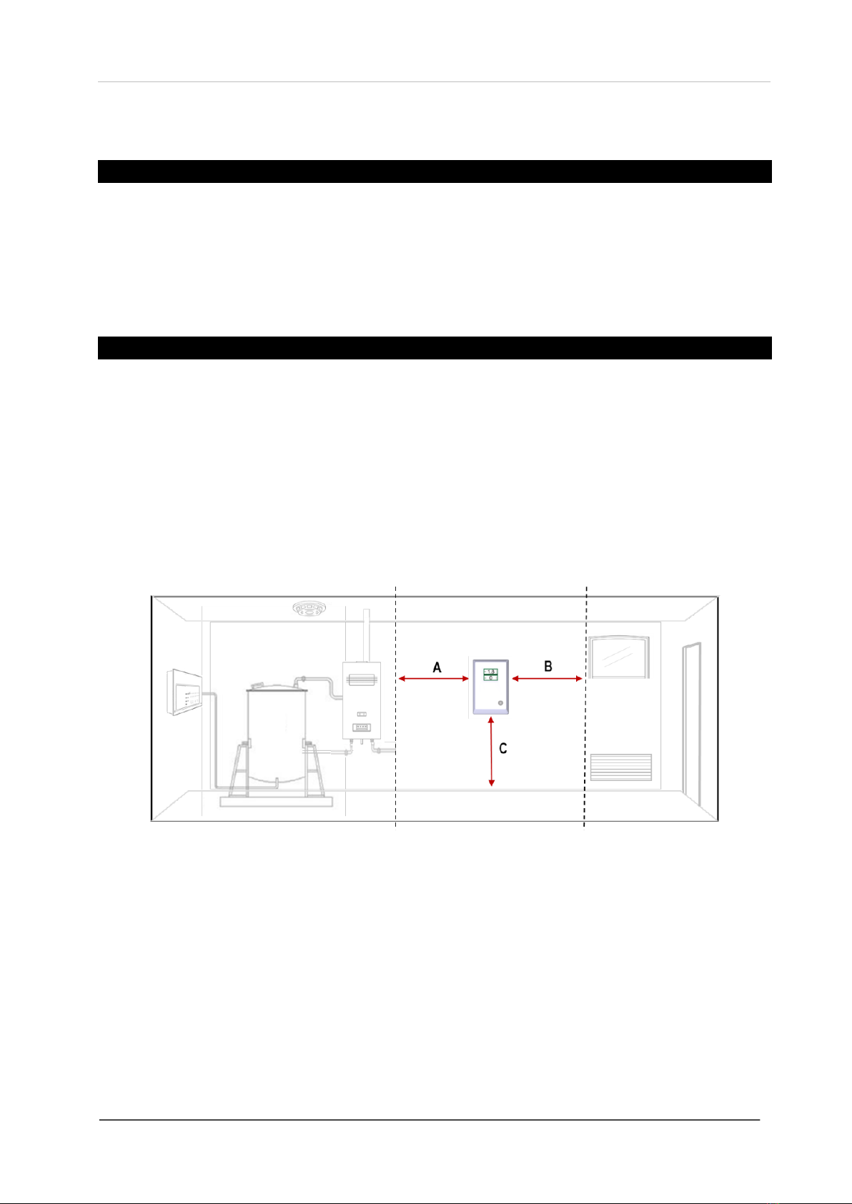
Typical Location and Positioning
Consider the coverage required and function of the area. Emphasis should be placed on airflow patterns
and correct placement, not perceived detecting ranges. The target gas will only be identified when
contact is made with the sensing element itself.
Multiple detectors may be required to adequately protect property and persons.
Locations for detectors will vary based on the intended application, they should be located near identified
sources of a potential gas leaks / pockets where hazardous gas could quickly accumulate and areas of
identified consequential risk.
A. 6ft from sources of combustion e.g. boiler s/ heaters / gas fired appliances etc.
B. 4ft from draft zones and ventilation areas e.g. windows, doorways and A/C units etc.
C. 5ft from ground level.
Recommended heights may vary based on air flow and temperature conditions in addition to the
proposed application and location. The device should be mounted near the boiler or gas fired appliances
such as domestic & commercial boiler rooms and basements.
When choosing your location, make sure you are able to hear the alarm from all areas.
Avoid conditions of any other environmental factors that could potentially impede the accuracy and
operation of the detector such as; condensation; vibration; temperature, pressure, the presence of other
gases, electromagnetic interference and draft zones.
Installation, Operation & Maintenance Mini-Merlin
Rev: 1 01-21 7
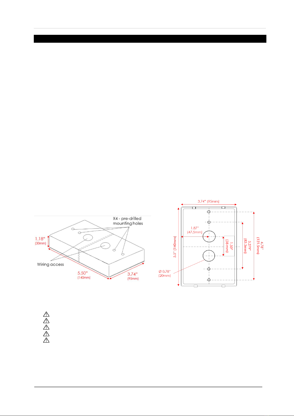
Mounting
Unpack all the parts!
This device is designed for either surface mounting, or mounted on a one or two gang electrical box and
must be installed by a licensed, insured contractor.
This device comes with a deep base back cover and barrier slip to maintain segregation between high
and low volt connections.
A flush mount base is available –Contact your supplier for more information.
1. Carefully remove the rear cover from the unit by releasing the two latching clips with a small flathead
screwdriver.
2. Using the rear cover - mark the screw holes to the wall or align with the electrical box. If mounting
direct to wall - ensure the wall surface is flat to prevent base distortion.
3. There are pre-fractured areas for cable entry and barrier to separate low and high volt connections.
4. Mount at 5 feet from ground level and in accordance with any applicable regulations.
5. After executing the mounting and connections –secure the rear cover.
Take care when making connections to high voltage connectors!
Any damage attempting to remove the circuit board may void any warranty!
All Class 2 wiring is to be installed within flexible tubing to maintain segregation between circuits!
Wiring of different circuits shall be separated by means of routing, clamping or barrier!
All wiring shall be made of copper!
Installation, Operation & Maintenance Mini-Merlin
Rev: 1 01-21 8
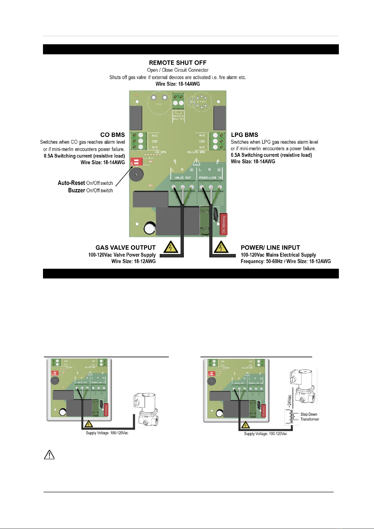
Board Overview
Wiring
GAS VALVE
A gas solenoid valve should be powered using the terminals marked [VALVE OUT].
When the valve out terminal is wired to a normally closed (NC) gas solenoid valve, the device can be used
to isolate the gas supply for multiple appliances.
Use an external transformer (not supplied) to close a 24VAC gas solenoid valve that could supply gas to
one or more appliances.
Gas Supply Controlled by 100-120VAC Solenoid Valve Gas Supply Controlled by 24VAC Solenoid Valve
We do not recommend installing a gas solenoid valve with standing pilots!
If you use a gas solenoid valve, please note that standing pilots will need to be re-lit!
Installation, Operation & Maintenance Mini-Merlin
Rev: 1 01-21 9
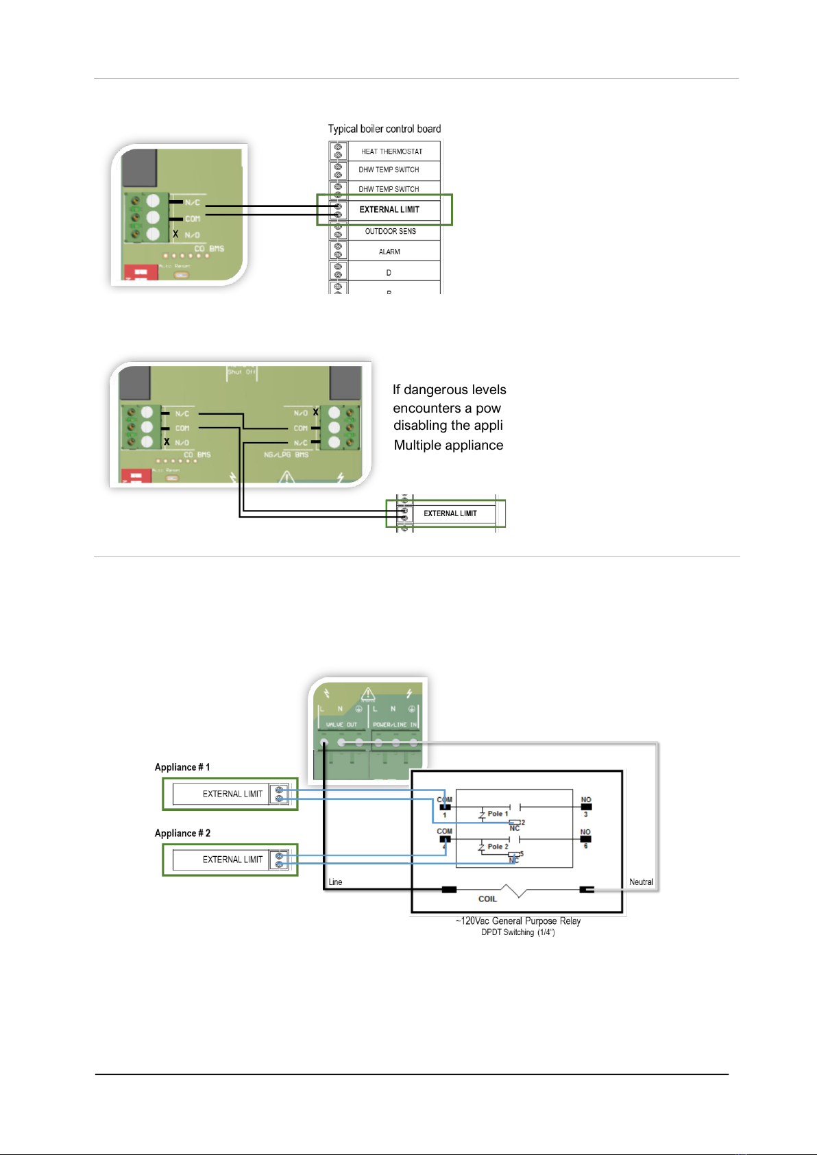
APPLIANCE LIMIT CIRCUIT
The device can be used to directly shut
down a gas appliance when a fault condition
is detected (gas leak) by wiring terminals of
one BMS into the low voltage safety limit
circuit of the appliance.
To connect both BMS to the safety limit circuit of an appliance - wire in series.
If dangerous levels of gas are detected or the mini-merlin
encounters a power failure, the circuit is opened,
disabling the appliance.
Multiple appliance limit switches can be wired in series.
ADAPTABLE OUTPUTS
The mini-merlin can be used to effect external relays and contactors to disable multiple appliances when a
fault condition is detected. Multi-pole relays can interrupt power to electrical circuits controlling boiler,
valves and pumps.
Low voltage wiring is to be inserted into the external limit circuit of a gas appliance.
The diagram shows a 120VAC general purpose primary coil with two sets of switches, each with
Normally Open (NO) and Normally Closed (NC) contacts. These contacts are rated for up to 12A AFL.
They can be used to break a low or line volt limit circuit or completely remove power to an appliance.

Installation, Operation & Maintenance Mini-Merlin
Rev: 1 01-21 10
PILOT WATER HEATER & BOILER LIMIT BREAKER
The device can be used to directly shut the pilot of a water heater in an alarm or power failure state using
a product from Field Controls. The BMS terminals may also be used to connect to a home alarm system.
Wiring example as shown.
REMOTE SHUT OFF
Your mini-merlin can be integrated with remote devices with an open /close circuit via the Remote Shut-
Off volt free switch terminal.
This terminal has a factory fitted link installed.
This terminal is normally closed and will alarm when energised open
- isolating the gas supply.
When using this input, only the mains utility output shall de-energize. If you are using the CO or NG relay
to shut down a boilers external limit circuit you will need to wire the input in series with the relay output.

Installation, Operation & Maintenance Mini-Merlin
Rev: 1 01-21 11
Auto Reset & Buzzer
ON
OFF
Auto
Reset
In the event of a power loss –the mini-merlin will
restart automatically when power is restored.
In the event of a power loss –the mini-merlin will need to be
reset manually when power is restored.
This is the factory set condition.
Buzzer
The buzzer will sound every 15 seconds during pre-
alarm and continuously at alarm level.
This is the factory set condition.
The buzzer will not sound at any gas level.
Building Management System Integration
This device can be integrated with a Building Management System (BMS), a home alarm system, or be
used as part of a boiler low voltage safety limit to make or break a circuit on both gases separately, (valve
open or valve closed) depending on the system.
These switches can be used for a variety of purposes including triggering alarm contacts, operating and
external relay for multiple appliance shut-down and generating status signals for a BMS system.
Specification
Product:
Mini Merlin
Version:
LPGCO
Display
1.8” TFT – Thin Film Transistor
Screen Brightness
Non- adjustable
Initial Stabilisation Time
60 Seconds approx.
Power Input Voltage
100-120Vac / 50-60Hz
Valve Output Voltage
100-120Vac / 50-60Hz
Internal Fuse Rating
Anti-Surge 3.15A 250Vac
Current Consumption
3W Max
Accuracy @ 25°C / 77°F
± <10%
Operating Temp
32 –122°F 30-85%RH Non-Condensing
Audible Buzzer
65dB (controlled conditions @ 1 ft)
Volt Free BMS relay output
0.5A switching current (resistive load)
Wire Ratings
Min. 18AWG / 75°C min / Copper only.
Gas Sensor Type
LPG: Semi-conducting
Carbon Monoxide: Electromechanical
Gas Sensor Measuring Range
LPG: 500-10,000ppm
Carbon Monoxide: 0-1000ppm
Gas Value Pre-Alarm
LPG: >8% LEL
Carbon Monoxide: 25ppm
Gas Value Alarm
LPG: >10% LEL
Carbon Monoxide: >50ppm
Dimensions (Inch)
3.7(W) x 5.5(H) x 2.4 (D)
Weight
8.54oz Approx.
Installation, Operation & Maintenance Mini-Merlin
Rev: 1 01-21 12
Operation
First Power Up
When electrical power is supplied, press and hold the Touch button, the device enters a
stabilisation phase for approximately one minute –during this period the device is not
operational. If the mini-merlin has been configured to ‘auto reset’ – your device will power up
automatically when electrical power is supplied.
Reset the Device
To reset after an alarm - press the Touch button once.
If the device enters an alarm state, the gas level indicator will remain red to alert the user that a
high/dangerous level of gas has been detected, until the device is reset.
Manual Operation Test
This option gives the user the opportunity to test each output/contact in response to gas.
Press and hold the Touch button during normal operation.
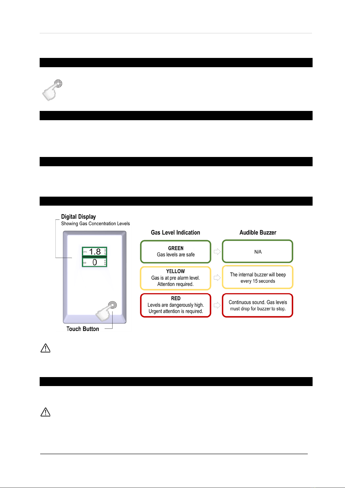
Display Overview
The user can choose whether to have the audible buzzer sound when gas levels are detected!
For more information see section ’Auto Reset & Buzzer switches’.
Power Off
To turn your device off, remove / isolate electrical power supply.
When power is removed manually or due to an unpredicted power failure the CO and NG BMS circuit will
change state switching off boilers/appliances via a limit switch if configured to do so!

Installation, Operation & Maintenance Mini-Merlin
Rev: 1 01-21 13
Gas Level Alarms
When alarms reach a RED status the maximum concentration level detected will be saved and the screen
value will switch between the maximum (MAX) and the real time current value!
When the device has reached an alarm state, the concentration indicator will remain red even if gas levels
are safe until the device is reset by pressing the Touch button once!
Remote Shut-Off Screen
This message will display if the device is integrated with remote shut off devices such as
smoke or fire alarms etc.
When activated, the device will isolate the gas supply if configured to do so.
End of Life Screen
This message indicates that the devices gas sensing elements have reached their expected
operational lifecycle. No gas levels will be displayed.
Contact your supplier and replace the unit immediately.
The expected lifecycle may vary depending on the environmental conditions!

Installation, Operation & Maintenance Mini-Merlin
Rev: 1 01-21 14
Maintenance & Testing
Cleaning
Keep your device in good working order - follow these basic principles;
Remove any dust/debris from the outer enclosure regularly using a slightly damp cloth.
Never use detergents or solvents to clean your device.
Never spray air fresheners, hair spray, paint or other aerosols near the device.
Never paint the device. Paint will seal vents and interfere with the device.
High concentrations of alcohol found in many products may damage, deteriorate or affect the gas sensing
elements –such as; wine; deodorants; stain removers; thinners!
Other gases and substances to avoid; Corrosives (i.e. chlorine & hydrogen chloride); Alkali metals; Basic
or acidic compounds; Silicones; Tetraethyl lead; Halogens and halogenated compounds!
Manual Operation Test
This option gives the user the opportunity to test each relay/output in response to gas.
When the touch button is pressed and held during normal operation the mini-merlin will simulate an open
circuit to ensure all configured systems, outputs, alarms, indications and other external devices operate as
intended in response to gas.
Gas Testing Overview
A detector may visually appear in good order, but its sensitivity can be inhibited by external factors such
as, dust; humidity; temperature fluctuations; cleaning products; contaminants or sensor drift (ageing). All
can cause a decline in sensitivity and eventual failure.
Regular ‘bump’ tests are important to make sure a device is able to detect a release of gas as early as
possible. We recommend that gas tests are carried out at least annually from the date of installation,
however the frequency should be determined following a risk assessment by the end user and in
accordance with any applicable law/code.
The aim of the bump test is to make sure a gas detector is working at its optimum by briefly exposing the
unit to a known concentration of the target gas. If the detector goes into alarm and all system
outputs/relays activate, then it is working safely.
If the system fails to operate as intended in an alarm state, the gas detector must not be used until a full
inspection and service has been conducted.
For more information on this, contact us.
Gas Sensor Types & Reaction Times
The time for gas sensors to react to their target gas will vary dependant on the type of gas detector/gas
sensing element. You should always refer to the appropriate specification for information including sensor
type and alarm levels i.e. electro-mechanical sensors (such as Carbon Monoxide) will react to its target
gas slower than semi-conducting sensor types (such as methane, LPG and Hydrogen).
Installation, Operation & Maintenance Mini-Merlin
Rev: 1 01-21 15
Gas Testing Kits
CGS provide a range of test gas kits traceable to appropriate standards and usually consist of:
•Certified gas cylinder / Spray.
•Flow control regulator / Control Valve
•Tube pipe / Applicator cone
All certified test gases are classified as non-flammable and non-toxic, however, they do contain gas under
pressure and may explode if heated to extreme temperatures and cause asphyxiation in high
concentrations.
Mini Merlin Gas Testing Procedure
Recommended** gas concentrations for testing your mini-merlin system.
Carbon Monoxide
250-500ppm balance in air.
Propane
6000-8000ppm balance in air (0.6%-0.8% BV)
**Reference should always be given to any applicable national & local law/ industry codes.
Generally, the gas concentration should be greater than the alarm threshold of the device.
GAS TEST PROCEDURE
1. Ensure you have the correct gas for the device type prior to application.
2. Screw the regulator/valve into the gas cylinder outlet.
3. Once sealed, the regulator pressure gauge (if available) will indicate cylinder pressure.
4. Offer up the applicator hose/cone and apply to the top vents of the device.
5. Open the valve/regulator to allow the gas to be delivered at a pre-set flow rate.
6. Apply gas.
7. The device will enter alarm status after a short period of time.
8. The device will activate all configured outputs/relays.
At this point…
9. Remove applicator hose/ cone and turn the gas cylinder regulator/valve off.
10. Once the device has returned to normal –Reset by pressing the Touch button.
11. Test complete.
12. Record your test details. There is a provision for this in this manual.
Always remove the regulator/valve after use!
All cylinders will re-seal upon removal of the regulator/valve!
Deviating from this test process is deemed improper and may affect the functional safety of your device!
Exposure to chemicals, smoke or any other materials other than the gases intended to be monitored can
seriously damage the gas sensing elements!
Always allow a minimum of 5 minutes before testing the same unit!
QUICK TIPS
To increase reaction time, cover the escape vents located underneath the device.
Alternatively, enclose the device and apply gas i.e. in an air tight bag or container.

Installation, Operation & Maintenance Mini-Merlin
Rev: 1 01-21 16
Test Gas Storage & Handling
All test gases are classified as non-flammable and non-toxic, however, they do contain gas under pressure
and may explode if heated to extreme temperatures and cause asphyxiation in high concentrations.
Cylinders should be stored in a vertical position secured to prevent them falling over.
Keep away from all sources of ignition.
Store in well ventilated areas.
Do not lift single cylinders by the valve device unless they are designed for that purpose.
Ensure valve/regulators are screwed and secured tight.
Always remove the regulator/valve after use and at the end of each working day.
Do not remove or deface cylinder labels.
Use all equipment in accordance with the Safety Data Sheet - available on request.

Installation, Operation & Maintenance Mini-Merlin
Rev: 1 01-21 17
Page intentionally left blank

Installation, Operation & Maintenance Mini-Merlin
Rev: 1 01-21 18
Test Record
Date
Gas Details
Pass
Sign

Installation, Operation & Maintenance Mini-Merlin
Rev: 1 01-21 19
Date
Gas Details
Pass
Sign

Installation, Operation & Maintenance Mini-Merlin
Rev: 1 01-21 20
Installation Details
Please pass this manual to the system owner / user.
Date of Installation:
Installation Location:
Organisation:
Stamp / Signature of the installer:
Canadian Gas Safety
Telephone: 647-577-1500
Canadian Gas Safety is the owner of this document and reserves all rights of modification without prior notice.
Table of contents
Other CGS Gas Detector manuals


Popular Gas Detector manuals by other brands


Evikon
Evikon PluraSens E2611-H2 user manual

S&S Northern
S&S Northern MERLIN CO DETECTOR X Installation operation & maintenance

mPower Electronics
mPower Electronics mSQUAD MP400S user guide

Rielta
Rielta SH-VTG installation guide

Herth+Buss
Herth+Buss ELPARTS SelectH2 mini operating instructions

Greystone Energy Systems
Greystone Energy Systems CDD Installation and operating instructions