BOREAL LASER GasFinder2 User manual

GasFinder2
BOREAL LASER INC.
Operation Manual
Boreal Laser Inc. GasFinder2 Operation Manual July 17th 2017
Part No. NDC-200023-C
Menu ver. V1.10.c
Portable System
12846 146 Street NW • Edmonton, Alberta • CANADA • T5L 2H7
Phone: +1 780 488 5173 • Fax: +1 780 488 0780 • www.boreal-laser.com

ii
Boreal Laser Inc. GasFinder2 Operation Manual July 17th 2017
Rev #2 June 2007 Sec. 5, 9 & Menu (ver. 0c43)
Rev #3 June 2009 All (ver. 1d03)
NDC-200023 August 2011 All (ver. V1.08.c)
NDC-200023-A January 2012 Title Pages (ver. V1.08.c)
NDC-200023-B October 2012 All (ver. V1.10.c)
NDC-200023-C July 17th 2017 Laser specs. (ver. V1.10.c)
BOREAL LASER INC.
Publications by Boreal Laser Inc.
Operation Manuals:
GasFinder2 NDC-200023-B
GasFinderFC NDC-200004-B
GasFinderFCr NDC-200005-B
GasFinderAB NDC-200006-A
GasFinderMC NDC-200010-B
GasFinderPT NDC-200021-B
GasFinder2 for
Multiple Path Monitoring NDC-200025-A
User Manuals:
GasViewOP NDC-200022-B
GasViewMC NDC-200013-B
GasMap NDC-200007-A
Accessory Manuals:
4-20mA Module NDC-200014-A
RF Barrier Module NDC-200027-A
DCR Module NDC-200016-A
Diagnostic and
Troubleshooting Kit NDC-200026
Copyright 2011 Boreal Laser Inc. All rights reserved.
Reproduction in any manner without the written permission of Boreal Laser Inc. is strictly forbidden.
Boreal Laser Inc. makes no representations or warranties with respect to the contents of this document.
Boreal Laser Inc. assumes no responsibility for errors or omissions or any damages resulting from the use of the
information contained in this document. Information in this document is subject to change without notice.
Ph.+1 780 488 5173 Fax +1 780 488 0780
E-mail <support@boreal-laser.com>

iii
Boreal Laser Inc. GasFinder2 Operation Manual July 17th 2017
Before operating the system, please read this manual fully to obtain the best results from
your product. The lightning flash with arrowhead inside the triangle, is intended to alert the
user to the presence of un-insulated dangerous voltage within the products enclosure that
may be of sufficient magnitude to constitute a risk of electrical shock to persons.
CAUTION:TOPREVENTTHERISKOFELECTRICSHOCK,DONOTREMOVECOVER(OR
BACK). NO USER-SERVICEABLE PARTS INSIDE. REFER SERVICING TO QUALIFIED
SERVICE PERSONNEL ONLY.
SAFETY INSTRUCTION:
Please read all the instructions herein.
Please heed all safety warnings. Please retain this manual for future reference.
Please install in accordance with these instructions.
WARNING
TO REDUCE THE RISK OF ELECTRIC SHOCK:
Do not expose this equipment to rain or moisture.•
Do not use the unit near water, and do not immerse in any liquid or pour any liquid on the unit.•
Servicing is required when the unit has been damaged in any way, such as the power-• supply cord or plug is damaged, liquid has been spilled or objects have fallen into the unit,
the unit has been exposed to rain or moisture, does not operate normally, or has been
dropped.
Refer all servicing to qualified personnel only.The equipment contains no user servicable parts.•
Note that if the equipment is used in a manner not specified in the manual,
the protection provided by the equipment may be impaired.
Removal of the equipment cover will void any warranty.
Disclaimer
Boreal Laser Inc. assumes no liability or responsibility for issues or harm resulting from the
use of this equipment.

iv
Boreal Laser Inc. GasFinder2 Operation Manual July 17th 2017
Contents
Section 1. System Description........................................................................................1.1
Specifications............................................................................................................... 1.3
GasFinder2................................................................................................................................. 1.3
Tripods........................................................................................................................................ 1.3
X-Y Mounts............................................................................................................................ 1.3
Scanning mount..................................................................................................................... 1.3
Certification........................................................................................................ 1.3
Accessories....................................................................................................... 1.4
Labels................................................................................................................ 1.4
Safety Concerns .......................................................................................................... 1.4
Section 2. Pre-Installation Checks.................................................................................. 2.1
Tools and Equipment.................................................................................................................. 2.2
Equipment Check ....................................................................................................................... 2.2
Section 3. Installation....................................................................................................... 3.1
Portable use................................................................................................................. 3.1
Retroreflectors............................................................................................................................ 3.1
GasFinder2................................................................................................................................. 3.1
Fixed Location.............................................................................................................. 3.3
Reflectors.................................................................................................................................... 3.3
Light Values................................................................................................................................ 3.3
Condensation.............................................................................................................................. 3.3
Reflector types............................................................................................................................ 3.4
GasFinder2................................................................................................................................. 3.5
General........................................................................................................................ 3.6
GasFinder Alignment.................................................................................................................. 3.6
Adjusting the Aiming Scope........................................................................................................ 3.7
Divergence.................................................................................................................................. 3.8
Magnetic fields............................................................................................................................ 3.8
Section 4. Data Input/Output........................................................................................... 4.1
DB15 Connector .......................................................................................................... 4.1
Serial Communications................................................................................................ 4.2
Data String Specification.............................................................................................. 4.2
Date and Time fields................................................................................................................... 4.3
4-20mA Option............................................................................................................................ 4.3
Data Transmission...................................................................................................................... 4.4
Downloading Data........................................................................................................ 4.5
4-20mA details ........................................................................................................................... 4.6
BOREAL LASER INC.
BOREAL LASER INC.
GasFinder2
Operation Manual

v
Boreal Laser Inc. GasFinder2 Operation Manual July 17th 2017
Section 5. Operating Instructions................................................................................... 5.1
Start Up........................................................................................................................ 5.1
Menu Details............................................................................................................................................ 5.3
Main Menus................................................................................................................................ 5.3
System Menus ........................................................................................................................... 5.5
Password Protected Menus........................................................................................................ 5.7
Section 6. Maintenance.................................................................................................... 6.1
GasFinder2.................................................................................................................. 6.1
Retroreflectors ............................................................................................................. 6.2
Section 7. Troubleshooting ............................................................................................. 7.1
Array Transfers ............................................................................................................ 7.3
Stability of Support Structures ..................................................................................... 7.5
Types of Supports....................................................................................................................... 7.6
Alignment Procedures for a Moving Building.............................................................................. 7.7
Centering ‘Scope cross hairs...................................................................................................... 7.8
Section 8. The Basics of Laser Gas Detection .............................................................. 8.1
Tuneable Diode Laser..................................................................................................8.1
Absorption Lines ......................................................................................................... 8.1
Gas Detection with a Laser..........................................................................................8.2
Retroreflectors ............................................................................................................. 8.3
Glossary of Common Terms and Abbreviations...........................................................8.4
Section 9. Appendices .................................................................................................... 9.1
Appendix A — Menu Structure..................................................................................... 9.1
Appendix B — Status Codes ....................................................................................... 9.3
Appendix C — Explanation of ppmm.......................................................................... 9.4
Appendix D — Explanation of R2 ................................................................................ 9.5
Appendix E — Conversion from ppm to mg/nm3......................................................... 9.7
Appendix F — 2-Way Serial Communication...............................................................9.8
Appendix G — Calibration ........................................................................................... 9.9
Appendix H — Cables................................................................................................ 9.10
Appendix I — Log to Memory ....................................................................................9.11
Appendix J — Remote Data Transmission............................................................... 9.13
Appendix K — Pre-Ship Parameterss........................................................................ 9.14
Appendix K — Accessories........................................................................................9.15
Section 10. Drawings ..................................................................................................... 10.1
1.Universal Enclosure base – PK1023UE – A Rev. D................................................ 10.3
2.GasFinder2.0 Enclosure – JB0102UE – Rev. Rev A .............................................. 10.5
3.GasFinder2.0 Dimensions – GF-D-3D-0003 – A..................................................... 10.7

vi
Boreal Laser Inc. GasFinder2 Operation Manual July 17th 2017
Power Supply
Measuring landfill gas
Measuring on smelter floor
Battery
Measuring through a duct Roof line installation in a fixed location
Plastic Enclosures

vii
Boreal Laser Inc. GasFinder2 Operation Manual July 17th 2017
GasviewOP Software Display
Large X-Y Mount for
fixed location Small X-Y Mount for
tripod
Vortex Cooler with GasFinder2
Air Inlet
Air Valve
Cold Air Diffuser
Thermostat
Air Filter
Vortex Cooler

viii
Boreal Laser Inc. GasFinder2 Operation Manual July 17th 2017
Product Warranty
Boreal Laser Inc. provides a standard warranty with the GasFinder2. The warranty covers
the GasFinder2 instrument plus spare parts ordered through Boreal Laser Inc.
For items covered by the standard warranty, Boreal Laser Inc. guarantees that during the
first 12 months following delivery, there will be no charges for parts or service required to
correct:
Equipment breakdowns•
Equipment malfunctioning•
Repeated or recurring faults or errors in the system.•
Instrument shipping and/or travel expenses for on-site service will be charged at cost.
Thiswarrantydoesnotapplyto situationswheresystemperformance hasbeencompromised
as a result of customer negligence or abuse or damage resulting from natural disasters.
Boreal Laser Inc. provides software upgrades and unlimited telephone and e-mail support
free of charge for the lifetime of the installation.
Extended warranty is available, see your Boreal Laser Inc. sales contact for information.
Procedure for returning the GasFinder2
If the unit has to be returned for service or repair, please contact Boreal Laser Inc. for a return
material authorization (RMA) number and form. An email will be sent containing complete
instructions on how to package the unit and containing a shipping address.
Tel: +1 780 488 5173
Fax: +1 780 488 0780
Email:support@boreal-laser.com

1.1
Boreal Laser Inc. GasFinder2 Operation Manual — System Description July 17th 2017
Boreal Laser’s patented (US Patent 5,637,872) TDL (Tunable Diode Laser) used in the
GasFinder2 measures gas concentration over an open path. The open path monitoring
system consists of an integrated transmitter/receiver and a remote, passive retroreflector
array. The remote retroreflector array is initially targeted by the operator using a two-axis
instrument mount assisted by a telescopic sight and an on-board visible red aiming laser.
The GasFinder2 houses the laser diode source, the transmitter and receiver electronics,
the transmitter and microcomputer subsystems. The GasFinder2 is weather proof and
has connectors for 12VDC power input, and data I/O. A schematic representation of the
GasFinder2 system is shown below in figure 1.
The laser light emitted from the transceiver unit propagates through the atmosphere to the
retroreflector and returns to the GasFinder2, where it is focused onto a photodiode detector.A
portion of the laser beam is passed through an onboard reference cell to provide line centering.
The returning optical signals are converted into electrical waveforms, which the computer
processes to determine the actual concentration of gas along the optical path. The computed
gas concentration is then displayed on the rear panel of the instrument, and can be transmitted
to a computer where the data can be collected, stored, and graphically displayed.
ItispossibletoaltersomeoftheparametersoftheGasFinder2remotelybyusingtheGasViewOP
software or another terminal program. These can be conected with the GasFinder2 using
suitable cables or radio equipment supplied by Boreal Laser Inc.
Fig. 1 Schematic representation of GasFinder2
Section 1. System Description
Control
Electronics
12VDC input
Data I/O
Keypad
Display
Laser
Diode
Detector
Computer
Calibration
Reference
Cell
Shutter
Aiming
Laser
Signal
Processing
&
Display
Remote
Retroreflector
Aiming Scope
1.2
Boreal Laser Inc. GasFinder2 Operation Manual — System Description July 17th 2017
The two main parts of the equipment are the Gasfinder2 and the Retroreflector.
GasFinder2
The• GasFinder2transceivercontainsthelaserdiodeandelectronics,
and can be mounted in a fixed location or on a tripod for portable use.
Therearpanel contains a LiquidCrystalDisplay(LCD)whichdisplays
the concentration in ppm/ppmm with an R2or Light Value indicator.
When required, the display can also show the system parameters
which are accessed with a keypad. The rear panel also contains the
power and I/O connectors. Specifications of the GasFinder2 are
given on page 1.3. The unit is configured by entering values with a
keypad or remotely with a terminal program or GasViewOP. These
values are described in the Menu Structure which contains three
subsections:
Main Menu — contains items such as path lengths, units, memory, etc.•
System Menu — contains arrays, real time clock, baud rates, etc.•
Password Protected Menu — contains calibration values.•
Details of the menus are given in Section 5 and a flow diagram is shown in Appendix A.
Retroreflector
Retroreflectors (Retros)• arepassive unitsand reflect the laser signal back to the GasFinder2.
For short distances (up to 50m), reflective tape can be used. For greater distances gold
plated, corner cube retros should be used.
The retros allow for alignment tolerance (i.e., they reflect the light straight back to source
independent of the angle of the reflector). The sealed enclosures can be provided with hoods,
desiccant packs, and in some cases heaters to reduce the effect of rain, condensation or
frost. The type of retro used will depend on the path length, atmospheric conditions such as
dust or fog, and the type of laser. Details of the retros are given on page 3.4.
Array containing
21 retroreflectors
Enclosure containing
4 retroreflectors and
a thermostatically
controlled heater
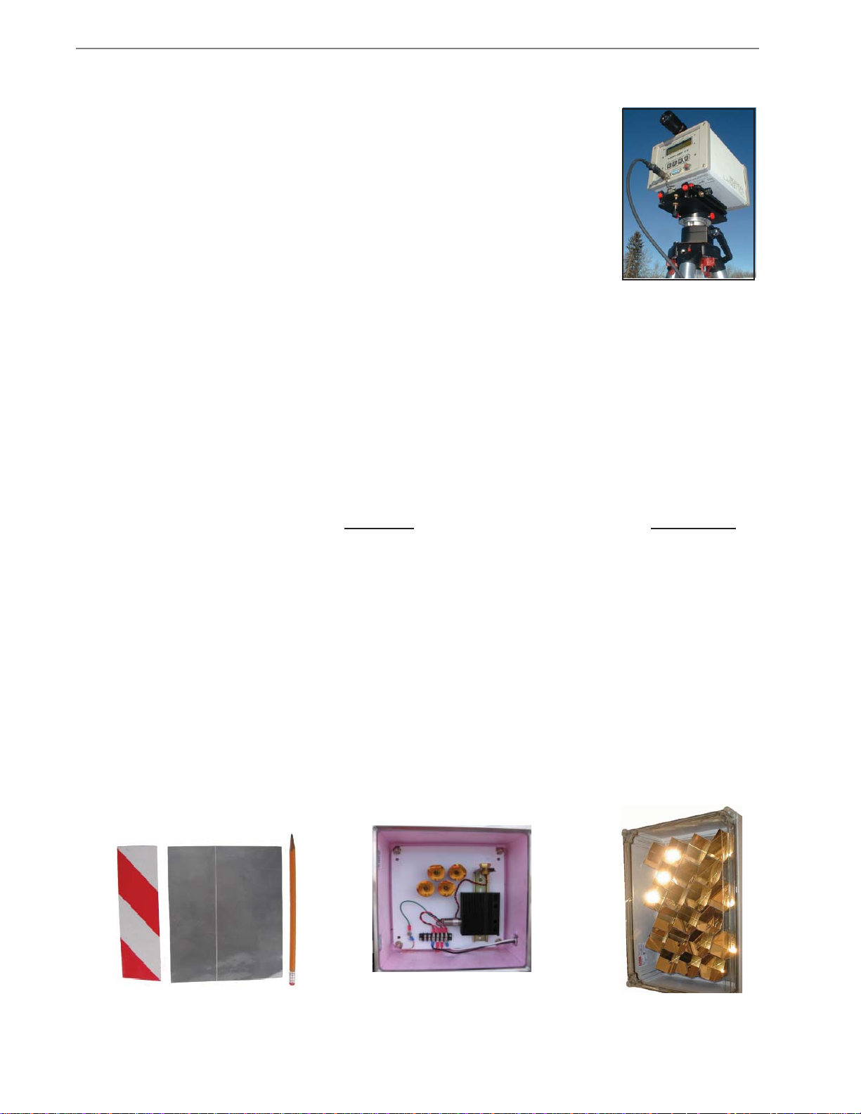
Retro Tapes
Gasfinder2 mounted
onthesmallX-Ymount
which is attached to
the tripod

1.3
Boreal Laser Inc. GasFinder2 Operation Manual — System Description July 17th 2017
Specifications
GasFinder2
Weight 5.2kg (11.5lbs)
Dimensions (L x W x H) 290 x 195 x 150mm (11.4 x 7.7 x 5.9 inches) See Section 10
Power Requirements 2A @ 12VDC
Operating Temperature Range -20C to +40C (HF +10C to +40C)
Scan Rate 1 sample / sec
Display 2 x 20 character Liquid Crystal Display
Laser Type Semiconductor
Laser Output 20mW (conforms to Class 1 as per IEC 60825-1}
Divergence 1.5 milli-radians
Alignment X-Y Mount, 3 - 9 x 40 Scope, visual laser.
Range 0.5m to 750m
Data Output RS232, serial data, CSV.
4-20mA current loop
Baud Rate (kbps) 0.3 / 1.2 / 2.4 / 4.8 / 9.6 / 19.2 / 38.4 / 57.6 / 115.2 / 230.4 kbps
Tripods
Large Tripod
Minimum Height 430mm (16.9 inches)
Maximum Height 2100mm (82.7 inches)
Weight 6.0kg (13.2lbs)
Small Tripod
Minimum height 560mm (13.2lbs)
Maximum height 1740mm (68.5 inches)
Weight 2.4kg (5.3lbs)
X - Y Mounts
Large X-Y Mount
Weight 4.8kg (10.6lbs)
Resolution
Horizontal 54 seconds of arc
Vertical 42 seconds of arc
Weight 1.4kg (3.1lbs).
Resolution
Horizontal 1.13 minutes of arc
Vertical 1.0 minutes of arc
Scanning Mount
Weight including Tripod 23.5kg (51.8lbs).
Resolution
Horizontal 1.2 minutes of arc
Vertical 1.2 minutes of arc
Certification
GasFinder2 CSA Class1, Division 2, Groups A, B, C, and D
when connected to NON-incendive supply not
exceeding 12.5VDC and 3A.
CE EN 50082-1 :1998
1.4
Boreal Laser Inc. GasFinder2 Operation Manual — System Description July 17th 2017
Labels
Safety Concerns
Boreal Laser’s GasFinder3-OP contains an invisible (infrared) laser source and a visible
(red) laser source for aiming.
Both the infrared and red lasers conform to Class 1 as per IEC 60825-1 and are eye-safe. They
do not require the use of protective eye wear, protective equipment, or outdoor control measures.
There is no optical ignition hazard presented by lasers of this type.
There are no user serviceable components contained in apparatus, all units must be returned to
factory for repair.
Caution: The infrared and red laser output from the GasFinder3-OP have very low
power (conforms to Class 1 as per IEC 60825-1) and will not damage eye tissue.
However, it is the recommendation of Boreal Laser Inc. that, as with ANY LASER
SYSTEM, the user/ operator should avoid staring directly into the output aperture of
the instrument.
Note that the laser beam is infra-red and is not visible to the eye.
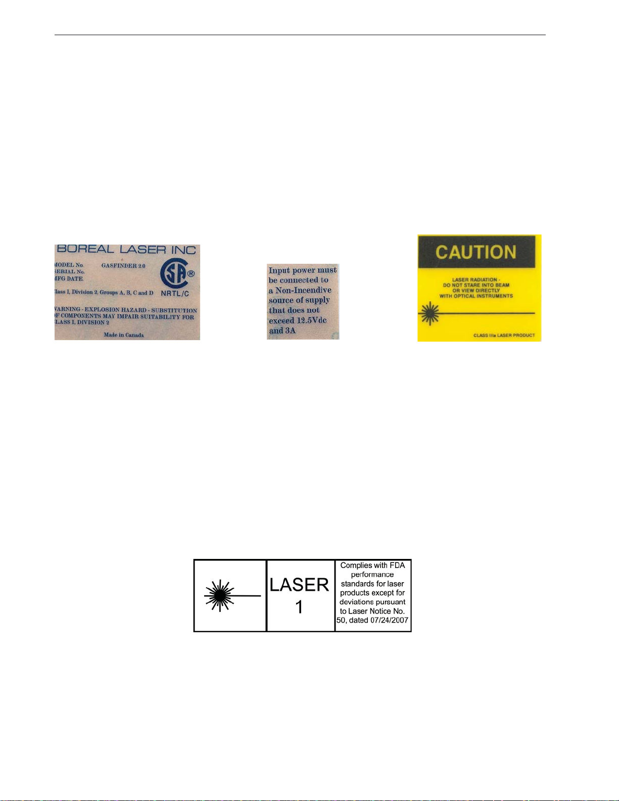
This label is affixed to the rear
of the GasFinder2 and gives
the instrument serial number
and manufacturing date as well
as the power requirements.
Thislabelisaffixedtotherear
of the GasFinder2 adjoining
the power socket.
This Caution label is affixed to
the front of the GasFinder2.
Accessories
Large X-Y Mount• Small X-Y Mount•
Scanning X-Y Mount• Tripods•
Vortex Cooler• Rangefinder• Radios•
— used for permanent sites.
— used in conjunction with a rotating base and a tripod for
portable work.
— used for automatic scanning
— tripods are supplied but any sturdy tripod with a
3/8” bolt can be used.
— Used in areas where the ambient temperature is above 400C.
— Useful for measuring path lengths.
— Used for remote data aquisition and control.

2.1
Boreal Laser Inc. GasFinder2 Operation Manual — Pre Installation July 17th 2017
Section 2. Pre-Installation Checks
There are two configurations for mounting the GasFinder2:
P• ortable Tripod Mount
F• ixed Mount
Portable Use on a Tripod
Thegroundorstructureatthetripodbaseshouldbefirmtominimise
movementandsettling.Pathsgreaterthan500mshouldbeavoided
if measurements are required for more than a few hours.
Fixed Use on a Large Mount
Fixed mount locations should be chosen to limit paths to 750m
and be in areas that are safely accessible for installation and
maintenance. Locations with dust or steam are to be avoided if
possible. The GasFinder2 can withstand small vibrations and
some translational motion but is extremely sensitive to rotational movement on long (>200m)
paths. The mounting must be rigid and well braced and kept separate from the structure used
to support personnel. Cables for power and data can be run in conduit or cable tray.
A site survey should be undertaken to check the following points:
Temperature limits• : the GasFinder2 should be located in an area where the
temperature does not go below *-200C or above 400C. A higher temperature can be
tolerated for a short time (1hr).
*Note that the lower limit for an HF system is +100C.
Power supply• : the GasFinder2 operates from a regulated,12VDC, 2A supply. This can
be from a 12V battery or a power supply module which converts the local supply voltage
(110V/220VAC) to 12VDC.
Accessibility• : safe access to the rear of the GasFinder2 should be possible.
Path• :locationsshouldbechosensuchthatalineofsightpathtotheproposedreflectorlocation
is unobstructed by traffic, dust, steam and limited to a maximum length of 750m. Mounting
locations on paths greater than 100m where sun can strike directly on the mount may require
special measures to prevent movement due to differential solar heating on the mount.
Retroreflectors (Retros)
Retroreflector locations should be in areas that are safely
accessible for cleaning when necessary. Locations with dust or
steam are to be avoided. Steam may pose a problem if it is dense
and consistently crosses the path.
Ifthelocationisoutsideandtheclimateishumid,arainhoodandsome
heating in the enclosure may be necessary to prevent condensation
on the window.This usually requires an outlet nearby to supply power
to a heater. The retros can tolerate small vibrations and movement,
so the retro mounting does not need to be as robust as the mounting
for the GasFinder2.
GasFinder2 mounted on
a tripod
Heater
Thermostat
Retros
Retros
2.2
Boreal Laser Inc. GasFinder2 Operation Manual — Pre Installation July 17th 2017
Tools and Equipment
A. Required:
Site-specific personal protective equipment.• Set of assorted cable ties if cabling is required.• Ladder and/or man-lift (as appropriate).•
B. Optional/Recommended:
Two-way radios (if permitted).• Range finder binoculars for portable work at different locations.•
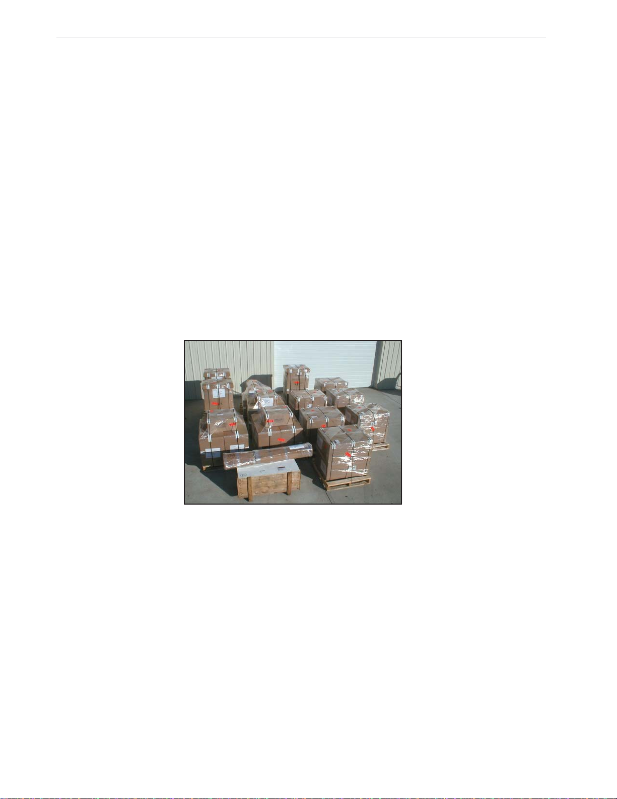
Equipment Check
Verify that all the equipment on the order sheet has arrived complete and in good condition.
Any damage due to shipping should be reported immediately and steps taken to obtain
replacement parts.
Order ready for shipment

3.1
Boreal Laser Inc. GasFinder2 Operation Manual — Installation July 17th 2017
Section 3. Installation
Safety IssuesCaution: The infrared and red laser output from the GasFinder3-OP have very low
power (conforms to Class 1 as per IEC 60825-1) and will not damage eye tissue.
However, it is the recommendation of Boreal Laser Inc. that, as with ANY
LASER SYSTEM, the user/ operator should avoid staring directly into the
output aperture of the instrument.
Note that the laser beam is infra-red and is not visible to the eye.
Sequence of the Installation:
The preferred sequence is to install the retro reflector first and then the GasFinder2. This
ensures that when the GasFinder2 is mounted, it can be aligned at the same time.
Portable use
Retroreflectors (Retros)
Theretroreflectorisavitalpartofthesystemandchoosingthecorrectone
is necessary for the correct operation of the system. Refer to pages 3.3
and 3.4 for details on choosing a retro. For short paths where reflective
tape is used, the tape can be attached to the back of an enclosure
which is fitted to a tripod or placed on a wall in any convenient location.
The angle of the tape can be adjusted to give an adequate signal return
provided this does not degrade the R2.
Where retros are used on longer paths, these may be mounted in
an enclosure on a tripod, or the enclosure placed in any convenient
location.
If ppmm is to be displayed, the GasFinder2 does not require any changes
when different path lengths are measured; the only change is to use a different retro to ensure
the correct value for the light.
GasFinder2
Setting up the Tripod
1. Holding the tripod vertically, free of the ground, press the
red lever (a) just under the head. This frees the brake on
the leg and allows it to extend. Do this for each leg in turn.
Alternatively, pressing levers (b) will allow all three legs to
come down at once. If the extension is not enough, the lower
portion of the legs can be extended by loosening the collar.
Spread the legs.
2. Position the tripod firmly on the ground with the height adjusted to be about level with the
operator’s chest.
On some surfaces the rubber feet should be screwed in to expose the pointed steel pin
which aids in gripping .
3. When the correct height is reached, tighten the screws on the three braces.
Red levers (a)
Red levers (b)
Retros in enclosure

3.2
Boreal Laser Inc. GasFinder2 Operation Manual — Installation July 17th 2017
4. If the swivel mount (c), is shipped separately, attach it
to the base of the X-Y mount (d), and then screw it to
the centre column of the tripod (e). Tightening the locking
screws (f) will make this easier.
5. The height of the centre column can be adjusted by
pushing the collar (g) in and setting the handle (h) to
the winding position. Loosen the locking screw (i) and
then the handle (h) can then be turned to increase or
decrease the height of the column. Tighten the locking
screw when the adjustment is complete to ensure the
rigidity of the mount.
Tip: To stabilise the tripod, a weight can be hung from the centre.
Setting up the Gasfinder2
6. Open the GasFinder2 carrying case and attach the alignment
scope to the channel on the top of the GasFinder2 with the
thumb screws attached to the scope (the scope end with the
adjusting ring faces the operator).
Note: The scope should not be used as a handle as the locking mechanism is not
designed for the weight of a GasFinder2.
7. Arm the quick release fitting on the X-Y mount by pressing
the small button (a) on the end of the lever (b) and moving it
anticlockwise until the brass button (c) is about 3mm above
the base. There will be a click when this occurs.
8. Remove the GasFinder2 from the case and press it into position
on the quick release fitting on the top of the X-Y mount. There will be an audible click when
the attachment is secure.
9. Use the swivel mount to align the GasFinder2 roughly with the retro and then tighten the
locking screws on the rotating base.
10.Loosen the red locking screws on the X-Y mount and, looking through the scope, use the
adjusting screws on the X-Y mount to align the GasFinder2 with the retro.The tripod legs
may have to be reset if the alignment is a long way out. Page 3.6 gives more details of the
alignment procedure.
11.Connect the power cable between the socket on the rear of the GasFinder2 and the
battery or power supply. Connect up a data cable if required.
12.Switch on the GasFinder2.
Refer to Section 5 for the operating instructions and details of the parameter settings.
A menu structure is shown in Appendix A.
Button (a) Lever (b)
Brass
Button (c)
Thumb Screws
Swivel
Mount (c) Locking
Screws (f)
Locking
Screw (k)
Handle
(h)
Collar
(g)
Centre
Column (e)
X-Y mount (d)

3.3
Boreal Laser Inc. GasFinder2 Operation Manual — Installation July 17th 2017
Fixed Location
Retroreflectors (Retros)
The retroreflector is a vital part of the system and choosing the correct type
is necessary for the correct operation of the system. Refer to page 3.4 for
details on choosing a retro. For short paths where reflective tape is used, the
tape can be attached to the back of an enclosure which is fitted to a tripod
or placed on a wall in any convenient location. The angle of the tape can be
adjusted to give an adequate signal return.
Where longer paths are measured, the retros can be mounted in an• enclosure placed in any convenient location with access for cleaning.
Where long paths are measured in metal buildings, the• GasFinder2
may go out of alignment as a result of solar heating deforming the building structure.
The preferred solution is to use multiple retros. See page 7.7.
Light Values
The type of retro used will depend on the path length, atmospheric conditions such as dust
or fog, and the type of laser. When choosing a retro, the prime concern should be to keep the
returning light level value between the preferred values of 4,000 and 8,000. The range of the
value is between 1000 and 16,368. Below 1000 the display will indicate “Low Light”. There is
no indication that the returning light has exceeded 16,368. When this happens the receiver
saturates and the displayed light value could read very low (<200). In this situation the gas
concentration readings will be in error and it is also possible to cause damage to the optical
components. The light value can be adjusted with the use of different retros.
Note: Care should be taken to ensure that the returning light does not exceed 14,000.
Condensation
Condensation on the surface of the window is caused by the window
temperature falling below the dewpoint. This may be occur in areas of
high humidity or large temperature differences between day and night.
The enclosures are well sealed but condensation can sometimes occur on
the inside of the window. Condensation can usually be controlled by the
following measures:
Fasten a cover over the enclosure to shield the window from the effect of• radiation cooling at night. It also prevents rain from striking the window.
Use a desicant pack inside the enclosure. This will only prevent• condensation inside the enclosure.
Place a heater in the enclosure. The heater can be from 12W to 50W• depending on the size of the enclosure and the conditions of operation
and is controled by a thermostat to prevent overheating. The heater
raises the temperature of the enclosure and prevents condensation
from forming either inside or outside the window. To minimise heat loss
the enclosure is insulated.
Radiation Shield
Enclosures with
heaters and rain hoods
4 Retros
Heater
Thermostat
4 retros and heater in
insulated enclosure

3.4
Boreal Laser Inc. GasFinder2 Operation Manual — Installation July 17th 2017
Reflector
Types Path
Length
Array of up to 76
63mm Retros 600m–750m
Description
Grey Tape comes in sheets 200mm x 300mm. It
is adhesive backed and can easily be attached to
any smooth, dry surface. It is often stuck to the
back of a retro enclosure.
Grey Tape 5m--40m
The tape comes in rolls 16m x 50mm wide. The tape is
divided into red and silver bands and each have different
reflective properties. The tape is adhesive backed and
can easily be attached to any smooth, dry surface. It is
often stuck to the back or side of a retro enclosure.
Red/White
Tape 1m--5m
These are multi-faceted IMOS 46mm hexagons.
They can be fitted together to make up a large
composite array.
IMOS Plastic
46mm Retro 30m--100m
The IMOS array shown is made from 14 single
hexagonal retros. They are normaly mounted
on a back plate which is placed in a stainless
steel or FRP enclosure.
IMOS Array 50m-- 300m
76 retros are probably the maximum number
that can be economically used as the cost
becomes prohibitive as the number of retros
increases. At path lengths greater than
750m, maintaining the correct alignment
becomes difficult.
These retros are enclosed in a PVC, RPF
or stainless steel enclosure. The number of
retros will depend on the type of gas being
measured, the path length and atmospheric
conditions. The window is normally Lexan
but can be changed to a special glass when
measuring some gases. For use outside,
rain hoods and heated enclosures are
recommended to prevent condensation.
Array of up to 6
63mm Retros 75m – 400m
This is a gold plated hexagonal retro. It is normally
housedin a plasticor steel boxwith a Lexan
window. They can also be fitted together to
make up a large composite array.
Gold Plated
63mm Retro 75m--150m
The enclosures will vary in size depending on the number of retroreflectors and if internal
heating is required. Window materials will depend on the site conditions and the gas to be
measured. Lexan is normally supplied but window glass, boro-silicate and sapphire are
used under specific circumstances. Contact Boreal Laser Inc. for more information.

3.5
Boreal Laser Inc. GasFinder2 Operation Manual — Installation July 17th 2017
GasFinder2
For fixed, long path installations, a concrete column is the preferred
construction material because a steel structure may deform due to the
thermal stresses caused by differential heating.
Note:Itis very importantthatthe Gasfinder2ismountedon astructure
separate from that used by the operators.
1. Bolt the large X-Y mount to the support base with the adjusting
screws towards the operator.
2. Open the GasFinder2 carrying case and attach the alignment scope
to the channel on the top of the GasFinder2 with the thumb screws
attached to the scope (the scope end with the adjusting ring faces the operator).
3. Remove the GasFinder2 from the case and place it onto
the X-Y mount. The rear of the GasFinder2 locks under
the angle at the rear of the mount and the two red thumb
screws at the front of the mount lock into the holes on the
front panel of the GasFinder2.
4. Connect the power cable between the socket on the rear of
the GasFinder2 and the 12V power supply and connect the
power supply to a power source.
5. Connect the data cable to the DB15 connector.
Attach the enclosure to baseplate.
6. Switch on the GasFinder2.
Details of the data protocol are given in Section 4
In the roof line of a smelter
Note that the support
for the GasFinder2
is from the roof and
is separate from the
maintenance platform
Guard rail for
maintenance
platform
GasFinder2
Power
Supply
Data
Connection
box
Concrete Column
Support Base
Thumb
Screws
Angle Lock
Plastic enclosure

3.6
Boreal Laser Inc. GasFinder2 Operation Manual — Installation July 17th 2017
GasFinder2 Alignment
General
If the retro is not visible in the alignment scope or difficulty
is experienced getting a reading of light level, the red visible
laser can be used to align the main laser.
With the• GasFinder2 in the Main Menu mode, scroll
down to the Light Value / Distance item.
Using the continuous red beam now being emitted from• GasFinder2, the X-Y mount can be adjusted so that the
red beam is reflected back from the retro.
As soon as the Light Value indicates a reading above 100, the visible laser use can• be discontinued and the maximisation of the Light Value reading used for precise
alignment.
Note: The reflected beam of the visible laser is very bright and should not be observed
through the scope.
The range of the light value is between 1000 and 16,368 but the preferred value is between
4000and8000. Below 1000 the displaywillindicate“LowLight”.Thereisnoindicationthatthe
returning light has exceeded 16,368 so care should be taken to ensure that the returning light
does not exceed 14,000. The light value can be adjusted with the use of different retros.
Note:If theguidelinesonpage3.3havenotbeenfollowed,itispossibletogettoomuch
light returned (>16,368). When this happens the receiver saturates and the displayed
light value will read very low (<200). In this situation the gas concentration readings
will be in error and it is also possible to cause damage to the optical components.
Table of contents
Other BOREAL LASER Gas Detector manuals

Popular Gas Detector manuals by other brands


Tokyo Gas Engineering Solutions Corporation
Tokyo Gas Engineering Solutions Corporation LaserMethane SMART LM2B03N-SBA operating instructions

DOD Technologies
DOD Technologies ChemLogic Revive CL4R operating manual

Chacon
Chacon 34151 user manual

Satel
Satel DG-1 manual

Gas Detection
Gas Detection GDA 3000 operating manual

Dräger
Dräger CMS Instructions for use