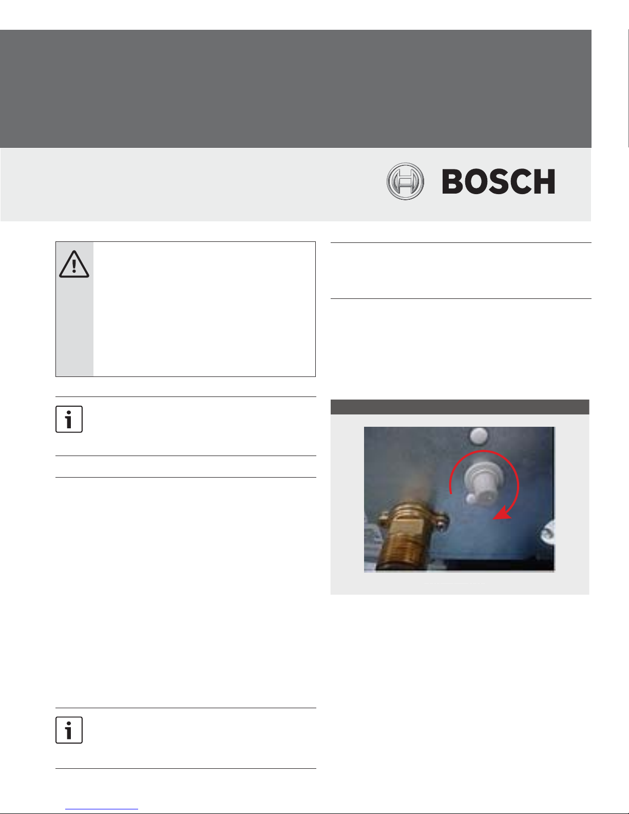
Bosch WH17 User manual
Other Bosch Boiler manuals

Bosch
Bosch Condens 8300i W User manual

Bosch
Bosch Buderus SB625WS User manual

Bosch
Bosch Greenstar FS User manual

Bosch
Bosch KBR16-3 Quick guide

Bosch
Bosch GREENSTAR HEATSLAVE II EXTERNAL 12/18 User manual

Bosch
Bosch WORCESTER GREENSTAR Ri ErP Series User guide

Bosch
Bosch WORCESTER benchmark Greenstar 24i User manual

Bosch
Bosch Condens 7000 F Instruction Manual

Bosch
Bosch Jungers ELAFLUX ED 18-1 HE User manual

Bosch
Bosch Greenstar Camray Utility 12/18 User manual

Bosch
Bosch CONDENS 5000W User manual

Bosch
Bosch Worcester 9/14CBI User manual

Bosch
Bosch UT-L 1 Quick start guide

Bosch
Bosch Stora WP 180 P1 User manual

Bosch
Bosch Worcester Greenstar Ri ErP + Series User manual

Bosch
Bosch WORCESTER DANESMOOR UTILITY 12/14 User guide

Bosch
Bosch Worcester Greenstar 8000 Series User manual

Bosch
Bosch WORCESTER benchmark Greenstar 12i User manual

Bosch
Bosch Worcester benchmark Greenstar 25Si User manual

Bosch
Bosch Greenstar Series Operating instructions


Popular Boiler manuals by other brands

Vaillant
Vaillant uniSTOR VIH SW GB 500 BES operating instructions

Radijator
Radijator BIO max 23.1 instruction manual

Brunner
Brunner BSV 20 Instructions for use

Buderus
Buderus Logamax GB062-24 KDE H V2 Service manual

Potterton
Potterton 50e Installation and Servicing Manual

UTICA BOILERS
UTICA BOILERS TriFire Assembly instructions

Joannes
Joannes LADY Series Installation and maintenance manual

ECR International
ECR International UB90-125 Installation, operation & maintenance manual

Froling
Froling P4 Pellet 8 - 105 installation instructions

Froling
Froling FHG Turbo 3000 operating instructions

U.S. Boiler Company
U.S. Boiler Company K2 operating instructions

Henrad
Henrad C95 FF user guide

NeOvo
NeOvo EcoNox EF 36 user guide

Potterton
Potterton PROMAX SL 12 user guide

Eco Hometec
Eco Hometec EC 25 COMPACT Technical manual

Viessmann
Viessmann VITODENS 200 Operating instructions and user's information manual

Baxi
Baxi Prime 1.24 installation manual

REXNOVA
REXNOVA ISA 20 BITHERMAL Installation, use and maintenance manual