manuals.online logo
Brands
  1. Home
  2. •
  3. Brands
  4. •
  5. Bosch
  6. •
  7. Dryer
  8. •
  9. Bosch WTA34 Series Setup guide

Bosch WTA34 Series Setup guide

REPAIR INSTRUCTIONS
r120085e -15/1
04.99
TUMBLE DRYER
Vented WTA34.. / WTA35..
I. SAFETY INFORMATION Page 1
II. OPERATION Page 1
III. DESCRIPTION OF FUNCTION / TECHNICAL INFORMATION Page 2
IV. CONSUMPTION RATES / ENERGY REQUIREMENT / OTHER DATA Page 6
V. REPAIRS Page 7
VI. SUPPLEMENTS Page 13
I. SAFETY INFORMATION
Before commencing repairs, ALWAYS disconnect the appliance from the power supply!
If tests have to be performed while the appliance is live, ALWAYS use a residual-
current-operated circuit-breaker! When repairs are complete, perform a function test, as
well as a safety test in accordance with VDE 0701.
1. Safety test in accordance with VDE 0701
•Plug in the tester mains plug.
In the case of switchover models connect L1 and L2 on the tester.
•Switch on the appliance (door must be closed).
•Perform the test.
II. OPERATION
1. Selecting the programme
•“Cottons/coloureds” Turn the programme selector in a clockwise direction to the
desired drying setting (6 automatic drying settings).
•Easy-care Turn
the programme selector in an anti-clockwise direction to the
desired setting (5 automatic drying settings).
•Timed programme Turn programme selector / time switch to the desired time.
2. Buttons
•ON/OFF Switches the appliance on / off.
•“Low heat” For delicate textiles. The temperature is reduced.
TUMBLE DRYER
r120085e -15/2
04.99
•Signal Button
pressed (LED on) – signal emitted in the “anti-creasing”
phase.
Changing
t
h
e v
olum
e – h
old
d
ow
n t
h
e b
utton
, t
h
e s
igna
l c
hanges
.
When the button is released, the volume has been changed
and stored.
Switching off the signal – press the button again (LED off).
•Start time* The start time can be specified from 1–19 hours. The running
time is indicated by a flashing dot in the 7-segment display.
The “anti-creasing” phase is extended to 8 hours.
If the Start button is pressed, the appliance starts immediately.
If the door is opened during the preselected time,
the Start time LED flashes, press the Start time button again –
the LED switches to a steady light.
* Optional (WTA3480; WTA3500)
3. Programme progress indicator
Dampness in the washing is continuously checked by the electronic sensor system.
The programme status is displayed by an LED.
III. DESCRIPTION OF FUNCTION / TECHNICAL INFORMATION
1. General information
The
design is based on a fully electronic solution. All control functions are combined on the
power
module. The selected drying setting is
determined by a conductivity measurement.
The conductivity measurement of the washing is converted to a voltage measurement.
Sliding contact
earth
Washing
resistance
Sliding contact
driver electrode
Sliding contact
driver electrode
Insulation
Slipring
Drum wall
Input
Micro-
controller
+5 V
TUMBLE DRYER
r120085e -15/3
04.99
•Operating and display module is situated in the fascia.
•Control and power module is situated on the right frame support.
•Thermistor sensor for measuring the air temperature.
•Condensation
pump is situated in the base group underneath the belt tensioning device.
•Motor is situated on the right in the base group.
•Heater on the rear panel – under the heating duct cover.
•Bimetallic thermal cut-out (>170 °C) is situated directly on the heater.
1.1 Operating and display module
The
operating and display module is used to input and output
information. It houses all the
direct input buttons, all signalling elements, e.g. LEDs, selector switches and signal
transmitters. Models are encoded by breaking off the side bridges.
1.2 Control and power module
The module houses all the significant components, e.g. micro-controller, relays, power
supply, etc. It performs complex functions with respect to controlling drying sequences,
monitoring the temperature, ascertaining parameters and actuating the operating and
display
section. The appliance is switched over from 16 A to 10 A by means of a wire jumper
.
Wire
jumper closed 16 A – Wire jumper open 10 A. Control and power module
≥
mask V 4.00
(software
version is indicated on the processor) changes automatically from 16 A to 10 A.
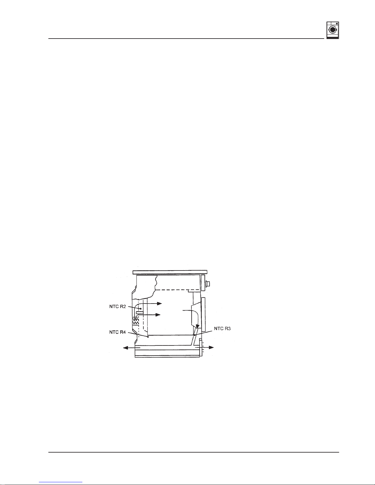
1.3 Thermistor sensor for measuring the air temperature
Thermistor
sensors measure the temperature of the process air at three dif
ferent points
in
the appliance (NTC thermistor – NTC stands for Negative Temperature Coefficient).
NTC R3
is situated in the ring insert under the door and measures the exhaust-air temperature.
NTC R4
is situated in the air current in front of the heater.
TUMBLE DRYER
r120085e -15/4
04.99
Resistance values NTC R3 / NTC R4
Temperature
°CResistance
kΩ
25 9–11
60 2.3–2.7
NTC R2
is
situated above the heater and measures the temperature
of the process air blown into the
washing.
Temperature
°CResistance
kΩ
25 18–22
60 4.5–5.5
1.4 Motor
The motor drives the drum and the fan.
Specifications:
Rated input when appliance empty: 140 W
Current input when appliance empty: 0.5 A
Motor capacitor, capacity: 11 µF
Nominal frequency: 50 Hz
Nominal voltage: 230 V
1.5 Heater
The heater consists of two heating coils E2, E3, the bimetallic thermal cut-out B9 and the
NTC R2.
Heat setting 2: 1200 W
Heat setting 3: 1800 W
1.6 Bimetallic thermal cut-out (heater)
The
thermal cut-out should respond when localised overheating occurs, e.g. if the air flow or
electrical temperature control fails.
If a fault occurs, the thermal cut-out must be manually actuated by pressing the red reset
button.
Response temperature: 160–175 degrees Celsius
1.7 Door switch and safety functions
All
relay activations are controlled via the door switch.
When the door is open, relays cannot
be activated.
When
the door is closed and the mains switch is on, the capacitor is charged via a processor
output. Its voltage is monitored by an analogue input.
TUMBLE DRYER
r120085e -15/5
04.99
When the door is opened, the capacitor is discharged. If a voltage of less than 1.5 V is
measured
on the capacitor when the machine is switched on, either
the door was opened or
a
mains failure lasted too long while the appliance was switched of
f. The programme must
then
be restarted. If the voltage on the capacitor is still suf
ficiently high, the programme is
reset and restarted following a voltage interruption.
Door switch F1
Closed Open
Micro-controller
Output
Analogue input
2. Principle of heating control
As the heater consists of 2 phase windings which operate at different power levels,
a different heating control can be used at various heat settings.
Heat setting 0 = OFF
Heat setting 2 = E3
Heat setting 3 = E2 + E3
The heat setting which is active is dependent on the programme sequence and on the
temperatures behind the heater (NTC R2) and on the drum outlet (NTC R3). If the motor
rotates in an anti-clockwise direction, the current heat setting is reduced by one
(Heat setting 3 ⇒Heat setting 2 or Heat setting 2 ⇒Heat setting 0).
Max.
Min.
Heat
setting
The maximum heat settings and minimum temperature values (NTC R2, NTC R3)
permitted for a programme section have been defined in the drying programme.
Both temperatures are monitored in parallel, the reset temperature having higher priority.
TUMBLE DRYER
r120085e -15/6
04.99
If
the maximum temperatures
are exceeded and Heat setting 0 has still not been reached,
the heater setting is reduced by one and is maintained for 20 s.
During this time the temperatures are monitored. If they do not drop below the maximum
values, the heat setting is reduced again. Conversely, the heat setting is increased if the
temperatures
drop below one of the minimum values and the maximum heat setting has still
not been reached.
ϑ
Min.
Max.
Limit
Heat
setting
3 or 2
0
If
the temperature limit is
exceeded, all heaters are switched of
f. The heater is not switched
on
again until the temperature has dropped to
υ
min. If the temperature does not drop below
the temperature limit within 10x30 sec., the drying process is terminated and an
“Overheating” error message (extra dry LED) is output.
IV. CONSUMPTION RATES / ENERGY REQUIREMENT / OTHER DATA
1. Energy-efficiency class “C”
2. Energy consumption
Spin speed in r.p.
Approx. values Drying time in minutes
(including 4 min.
cooling-down Approx.
time) values
Energy consumption
in kWh
Approx. values
“Cottons/coloureds”
4-5 kg Cupboard dry
Iron dry
1400
800
1400
800
(10/16A) 75/55
(10/16A) 105/80
(10/16A) 55/40
(10/16A) 77/58
2.4
3.3
2.4
2.5
Easy care 2 kg
Cupboard dry 1.000 (10/16A) 31/27 1.0
The indicated consumption values are guide values which have been determined under
normal
conditions. Fluctuations up to 10 % are possible. Low ambient temperatures in
the
installation location of the vented dryer will result in longer drying times.
TUMBLE DRYER
r120085e -15/7
04.99
V. REPAIRS
1. Troubleshooting
When implementing troubleshooting procedures, please comply with the following:
•All test programmes should be run.
•If “Test component” is indicated in the Procedures column of the troubleshooting
table the components are to be tested in accordance with their electrical specification.
To test the component, remove the plug from the power module.
•Check that the plug-and-socket connections are properly attached.
•If electronic modules are replaced, note down the result of the test programs on the
appropriate label.
•When handling electronic modules, comply with the EGB handling regulations.
•Put the replaced electronic modules back into the original packaging.
Error
no. Error display Possible cause Test / Procedure
1“Drying” LED flashes
in the progress
indicator = NTC fault
(NTC R4)
A
Appliance ambient
temperature < 0 °C. Customer instruction:
Do not operate the
appliance below 0 °C.
B
NTC R4, cable or plug-and-
socket connection defective. Remove the cable from the
power module. Test NTC,
cable and plug-and-socket
connection.
C
Power module defective. If 1 A and 1 B are o.k., start
“BW cupboard dry” test
program. If LED in the
progress indicator displays
NTC fault, replace the
power module.
2“Iron dry” LED
flashes in the
progress indicator =
NTC fault (NTC R2)
NTC R3, cable or plug-and-
socket connection defective. See Error number 1.
3“Cupboard dry” LED
flashes in the
progress indicator =
NTC fault (NTC R2)
NTC R2, cable or plug-and-
socket connection defective. See Error number 1.
4 “Extra dry” LED
flashes in the
progress indicator =
overheating
A
Fluff filter blocked. Clean the fluff filter.
TUMBLE DRYER
r120085e -15/8
04.99
Error
no. Test / ProcedurePossible causeError display
Re 4 B
Air-intake / exhaust-air
passages blocked. Test air passages.
C
Overload Customer instruction:
Load < 5 kg dry weight.
D
Fan impeller loose. Test fan impeller.
E
Motor is not rotating. See Error number 7.
F
Heater does not switch off. See Error display 8 B/C.
5“End” LED flashes
(display only in test
program!) = time
error
– “Washing not
drying properly”
– “Drying time
too long”
– “Dry in 180 /
240 minutes”
A
Washing too wet,
initial moisture too high. Customer instruction.
B
Overload, < 5 kg dry weight. Customer instruction.
C
Fluff filter blocked. Clean fluff filter.
D
Thermal cut-out B9 has
tripped. See Error number 14.
E
Short-circuit or shunt circuit
in conductivity system. See Error number 12 B.
F
Heater defective. See Error number 8.
G
Motor is not rotating. See Error number 7.
H
Mains voltage too low. Measure mains voltage
under load.
Required voltage 230 V
(+10 % / –15 %).
TUMBLE DRYER
r120085e -15/9
04.99
Error
no. Test / ProcedurePossible causeError display
6Drum is not rotating. A
Motor is not rotating See Error number 7.
B
Belt loose, slipping or
defective.
Clamping device defective.
Test belt and clamping
device.
C
Drum blocked or
overloaded. Test drum.
7Motor is not rotating
– rotates only in one
direction,
– rotates constantly.
A
Motor, cable or plug-and-
socket connection defective.
Motor protector has been
actuated.
Motor capacitor defective.
Test motor, capacitor and
wiring.
B
Door switch defective. See Error number 15.
C
Power module defective. Start “BW cupboard dry”
test program and measure
drive voltage for motor.
Clockwise rotation:
Mains voltage between
X11–10.5 and X11–10.3;
Anti-clockwise rotation:
Mains voltage between
X11–10.5 and X11–10.4
Before performing this test,
remove the heater plug, as
thermal cut-out B9 will trip
immediately without the
motor.
8Is not heating. A
Thermal cut-out B9 has
tripped. See Error number 13 B.
B
Heater defective. Test heater and cable.
C
NTCs defective. Test NTCs (cold resistance)
and wiring.
TUMBLE DRYER
r120085e -15/10
04.99
Error
no. Test / ProcedurePossible causeError display
Re 8 D
Power module defective. Start “BW cupboard dry”
test program.
On the power module
measure the drive voltage
(mains voltage) for heater
E1, 2, 3.
E
Excessive contact
resistance in sliding contact
system.
See Error number 11 E.
9Heater continuously
on.
(Dryer not started.)
A
Heater defective. Test heater and cable.
B
Power module defective. See Error number 8 C.
10 – Washing not drying
properly,
– Too damp.
A
Wrong programme selected. Customer information:
Select higher degree of
dryness.
B
Door switch or power
module defective. See Error numbers 15 A
and 15 B.
C
Excessive contact
resistance in conductivity
system.
Start “Gentle dry” test
program. Short-circuit
between the agitator and
drum.
If an error is displayed:
Test sliding contact system
and internal contact
between agitators for
continuity.
Max. 1 kΩbetween agitator
and Pin 3 on the plug.
Max. 1 kΩbetween drum
and Pin 1 on the plug.
If resistance is o.k.:
Repeat test program, with
jumper between plug-and-
socket connection X11-15.1
and X11-15.3. If there is no
error display, do not replace
the power module.
TUMBLE DRYER
r120085e -15/11
04.99
Error
no. Test / ProcedurePossible causeError display
11 Washing too dry. A
Wrong programme selected. Customer information:
Select lower degree of
dryness.
B
Short-circuit or shunt circuit
in conductivity system. Start “Gentle dry” test
program. Do not short-
circuit between the agitator
and drum.
If an error is displayed:
Remove plug-and-socket
connection X11-5 from the
power module:
If an error is still displayed,
then replace the power
module.
If an error is not displayed:
Test the sliding contact
system.Remove
plug-and-socket connection
X11-5 from the power
module and measure the
resistance between Pin 1
and Pin 3 on the plug
(< 500 V). Insulation
resistance > 20 MΩ.
12 Appliance dries for
only 9–13 minutes. Empty drum, dry washing. Customer information:
After approx. 9–13 minutes
dryer recognises empty
drum and / or dry washing.
13 Thermal cut-out B9
has tripped. A
Motor is not rotating. See Error number 7.
B
Fan impeller loose. Test fan impeller.
C
Fluff filter blocked. Clean fluff filter.
D
Heater defective. Test heater and cable.
14 Start LED does not
switch to a steady
light, appliance does
not start.
Door not closed.
TUMBLE DRYER
r120085e -15/12
04.99
Error
no. Test / ProcedurePossible causeError display
Re 14 A
Door switch F1 and / or
locking mechanism
defective.
Remove plug X11–1 from
the power module.
Test switch, cable, plug and
mechanism
– Locking hook
– Bowden cable
– Door button
B
Power module defective. Remove plug from the
power module, short-circuit
Pin 7 and 5 on plug-and-
socket connection X11–1 on
the power module and start
any drying programme.
If the appliance starts, the
power module is o.k.
15 Appliance does not
start. Operating module defective. Activate test mode;
If this mode can be
activated, the operating
module is o.k. Check
whether the circuit board
has become detached from
the operating module.
If not, continue with Error
number 15.
16 Button, display or
programme selection
malfunctions
occasionally.
Operating module or power
module defective. Start “extra dry” and “very
dry” test programmes.
17 Filter LED flashes,
filter is clean. A
Overheating See Error number 4.
B
NTC R2 or NTC R4
defective. Remove the cable from the
power module.
Test NTC, cable and plug-
and-socket connection.
TUMBLE DRYER
r120085e -15/13
04.99
Error
no. Test / ProcedurePossible causeError display
18 Starts by itself when
switched on. Appliance was switched off
during a drying cycle. Customer information:
If the appliance switches off
and subsequently switches
on again while a drying
programme is running, the
appliance is starting by itself
in order to terminate the
programme which was
started.
VI. SUPPLEMENTS
1. Power and control module
Changed software mask 3 (software version V 3.00 is indicated on the processor).
⇒Reduced heat output in the time programme.
⇒Empty drum or dry washing identified within 5 minutes (–2 % relative humidity).
⇒Clocking at reduced heat output.
⇒No stop function when start button pressed again.
2. Spark discharge between belt clamping device and motor connector plug
Drive
belts were occasionally manufactured with an insuf
ficient carbon content, resulting in
a
static charge build-up between the belt wheel and drive belt. In
these cases the drive belt
(Mat. no.: 15 4142) must be replaced.
3. Improvement in temperature control in the heat registers
All heaters will receive a new thermal cut-out (modified design). Thermal cut-outs
(Mat. no.: 15 4132) and NTC (Mat.: no. 15 4186) are no longer available as spare parts.
If required, heaters in appliances with customer-service index /01 should be completely
replaced.
4. Increase to customer-service index /02
Individual
parts of the heater (NTC
and thermal cut-out) are available again as spare parts.
TUMBLE DRYER
r120085e -15/14
04.99
5. New control and power module
Appliances from FD 7704 will receive a new control and power module mask 4 (software
version V 4.00 is indicated on the processor).
⇒
Instead of “clocking” – “scan” conductivity measurement – identification of empty drum
or dry washing identified (4 minutes).
⇒Scan at changed reserve times 40 sec. on right / 20 seconds on left.
⇒Time remaining display in time programme in minutes (appliances with *
⇒Changed fluffing recognition system (filter / cooler). NTC R4 is not applicable.
⇒Changed temperature ranges of the NTCs. NTC R3 –15 °C / 105 °C.
NTC R2 –15 °C / 200 °C.
⇒Switchover model from 16 A to 10 A via test program.
♦Activate test program.
♦Set programme selector to rotary-iron dry.
♦Press Start button.
Display model ♦16 A model Display 16
“Low heat” LED on
♦10 A model Display 10
“Low heat” LED off
Switch over
model ♦Press “Low
heat” button Display and “Low
heat” LED flash
♦Press Start
button The last displayed
status is
acknowledged
6. Buzzer on the operating module
The
buzzer on the operating module is available as
a spare part (Mat. no.: 16 8577) from the
logistics centre in Fürth. When replacing the buzzer, note the polarity on the instruction
leaflet.
7. Increase to customer-service index /04
Control
and power module mask 5 (software version V 5.00 is indicated on the processor),
process
fan drum and heater new
. The modified software reduces the process temperature
(NTC R2 heater, NTC R3 exhaust air). Fan drum (process air) has been changed from
145 mm
to 155 mm. T
o obtain a more satisfactory measurement of the air flow
, the position
of the NTC and thermal cut-out on the heater has been changed.
*Etwas fehlt hier
TUMBLE DRYER
r120085e -15/15
04.99
8. Drum bearing at the rear
A new plastic drum bearing was used during the production period FD7710–FD7803.
The assembly kit (Mat. no.: 15 4177) is also available as a spare part.
See diagram for installation.
9. Increase to customer-service index /06
New
base group consisting of an upper and lower section. As the exhaust air distributor is
integrated, noise is reduced. The new base group has been in use since 08.98.

This manual suits for next models

1

Other Bosch Dryer manuals

Bosch Nexxt DLX Series Installation guide

Bosch

Bosch Nexxt DLX Series Installation guide

Bosch WTW87449SN User manual

Bosch

Bosch WTW87449SN User manual

Bosch WTUM45D00W User manual

Bosch

Bosch WTUM45D00W User manual

Bosch WTG86400AU User manual

Bosch

Bosch WTG86400AU User manual

Bosch WTWH7660GB User manual

Bosch

Bosch WTWH7660GB User manual

Bosch Programme Table User manual

Bosch

Bosch Programme Table User manual

Bosch Axxis WTA 4410 CN User manual

Bosch

Bosch Axxis WTA 4410 CN User manual

Bosch Programme Table User manual

Bosch

Bosch Programme Table User manual

Bosch WTW85430IL User manual

Bosch

Bosch WTW85430IL User manual

Bosch WTY87640WW User manual

Bosch

Bosch WTY87640WW User manual

Bosch WTR87TW0BY User manual

Bosch

Bosch WTR87TW0BY User manual

Bosch WTW85470GB User manual

Bosch

Bosch WTW85470GB User manual

Bosch DV52J8060E series User manual

Bosch

Bosch DV52J8060E series User manual

Bosch WTWH7560GB User manual

Bosch

Bosch WTWH7560GB User manual

Bosch WTN85200GB User manual

Bosch

Bosch WTN85200GB User manual

Bosch WTW855R9SN User manual

Bosch

Bosch WTW855R9SN User manual

Bosch WTE84301GB User manual

Bosch

Bosch WTE84301GB User manual

Bosch WPG23100IN User manual

Bosch

Bosch WPG23100IN User manual

Bosch WTG86261EE User manual

Bosch

Bosch WTG86261EE User manual

Bosch WTN86203IN User manual

Bosch

Bosch WTN86203IN User manual

Bosch WTS86519GB User manual

Bosch

Bosch WTS86519GB User manual

Bosch WTWH761BY/07 User manual

Bosch

Bosch WTWH761BY/07 User manual

Bosch WTG87249ES User manual

Bosch

Bosch WTG87249ES User manual

Bosch WTW894A8SN User manual

Bosch

Bosch WTW894A8SN User manual

Popular Dryer manuals by other brands

Alliance Laundry Systems ADE3SRGS173CW01 troubleshooting guide

Alliance Laundry Systems

Alliance Laundry Systems ADE3SRGS173CW01 troubleshooting guide

Blomberg TAF 7239 user manual

Blomberg

Blomberg TAF 7239 user manual

GE GTDS850EDWS installation instructions

GE

GE GTDS850EDWS installation instructions

Frigidaire GLER341CC0 operating instructions

Frigidaire

Frigidaire GLER341CC0 operating instructions

Frigidaire FARG1011MW use & care

Frigidaire

Frigidaire FARG1011MW use & care

Maytag 3395325 installation instructions

Maytag

Maytag 3395325 installation instructions

Speed Queen AE7133 Use and care guide

Speed Queen

Speed Queen AE7133 Use and care guide

GE DDC4400T Dimension Guide

GE

GE DDC4400T Dimension Guide

Hotpoint DLB6850B Use and care

Hotpoint

Hotpoint DLB6850B Use and care

Frigidaire FCED3000ES - 5.7 cu. Ft. Coin-Operated Electric... installation instructions

Frigidaire

Frigidaire FCED3000ES - 5.7 cu. Ft. Coin-Operated Electric... installation instructions

Crosley CEDX631VQ1 installation instructions

Crosley

Crosley CEDX631VQ1 installation instructions

Miele TOUCHTRONIC T 1405 operating instructions

Miele

Miele TOUCHTRONIC T 1405 operating instructions

Mediclinics Machflow quick start guide

Mediclinics

Mediclinics Machflow quick start guide

GE PSXH47 owner's manual

GE

GE PSXH47 owner's manual

Zanussi ZTH485 user manual

Zanussi

Zanussi ZTH485 user manual

GE 475 owner's manual

GE

GE 475 owner's manual

Maytag MDE2440 Owner's instructions

Maytag

Maytag MDE2440 Owner's instructions

Whirlpool AWZ 8CDS/DF quick start guide

Whirlpool

Whirlpool AWZ 8CDS/DF quick start guide

manuals.online logo
manuals.online logoBrands
  • About & Mission
  • Contact us
  • Privacy Policy
  • Terms and Conditions

Copyright 2025 Manuals.Online. All Rights Reserved.