IntuiKey Keyboard Safety | en 1
Bosch Security Systems, Inc. Installation Manual F.01U.115.018 | 1.92 | 2008.12
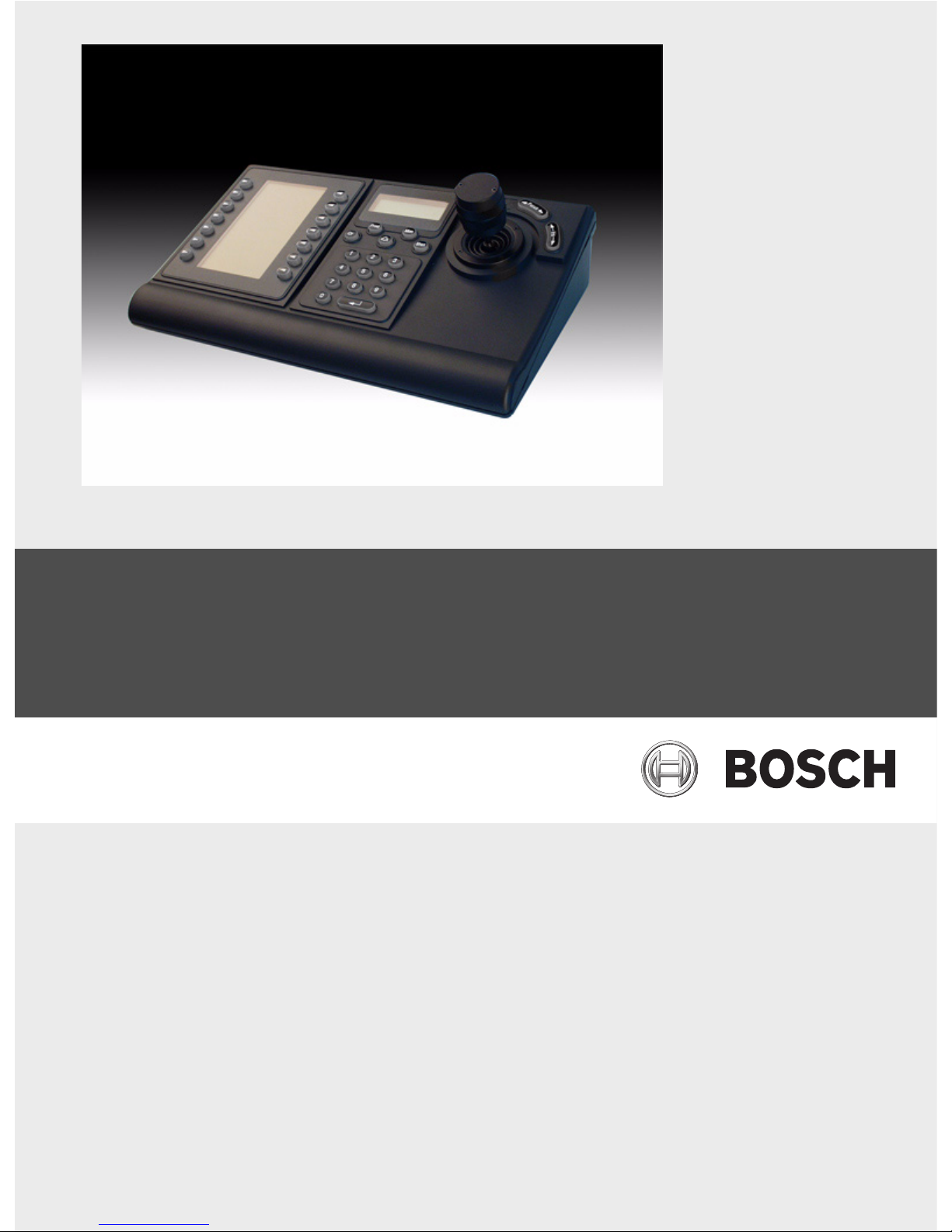
1Safety
1.1 Important Safety Instructions
Read, follow, and retain for future reference all of the following safety instructions. Heed all
warnings on the unit and in the operating instructions before operating the unit.
1. Cleaning - Unplug the unit from the outlet before cleaning. Follow any instructions
provided with the unit. Generally, using a dry cloth for cleaning is sufficient, but a moist
fluff-free cloth or leather shammy may also be used. Do not use liquid cleaners or aerosol
cleaners.
2. Heat Sources - Do not install the unit near any heat sources such as radiators, heaters,
stoves, or other equipment (including amplifiers) that produce heat.
3. Ventilation - Any openings in the unit enclosure are provided for ventilation to prevent
overheating and ensure reliable operation. Do not block or cover these openings. Do not
place the unit in an enclosure unless proper ventilation is provided, or the manufacturer's
instructions have been adhered to.
4. Water - Do not use this unit near water, for example near a bathtub, washbowl, sink,
laundry basket, in a damp or wet basement, near a swimming pool, in an outdoor
installation, or in any area classified as a wet location. To reduce the risk of fire or
electrical shock, do not expose this unit to rain or moisture.
5. Object and liquid entry - Never push objects of any kind into this unit through openings
as they may touch dangerous voltage points or short-out parts that could result in a fire
or electrical shock. Never spill liquid of any kind on the unit. Do not place objects filled
with liquids, such as vases or cups, on the unit.
6. Lightning - For added protection during a lightning storm, or when leaving this unit
unattended and unused for long periods, unplug the unit from the wall outlet and
disconnect the cable system. This will prevent damage to the unit from lightning and
power line surges.
7. Controls adjustment - Adjust only those controls specified in the operating instructions.
Improper adjustment of other controls may cause damage to the unit. Use of controls or
adjustments, or performance of procedures other than those specified, may result in
hazardous radiation exposure.
8. Overloading - Do not overload outlets and extension cords. This can cause fire or
electrical shock.
9. Power cord and plug protection - Protect the plug and power cord from foot traffic,
being pinched by items placed upon or against them at electrical outlets, and its exit
from the unit. For units intended to operate with 230 VAC, 50 Hz, the input and output
power cord must comply with the latest versions of IEC Publication 227 or IEC Publication
245.
10. Power disconnect - Units with or without ON/OFF switches have power supplied to the
unit whenever the power cord is inserted into the power source; however, the unit is
operational only when the ON/OFF switch is in the ON position. The power cord is the
main power disconnect device for switching off the voltage for all units.