Page
10 Mounting, demounting and electric installation............................................................ 25
10.1 Installation notes................................................................................................................................... 25
10.2 Housing dimensions............................................................................................................................. 25
10.3 Pin assignment..................................................................................................................................... 26
10.4 Mounting............................................................................................................................................... 26
10.5 Demounting.......................................................................................................................................... 27
10.6 Electric connection................................................................................................................................ 27
10.6.1 Procedure to connect the lines to X1S1/X1S2.................................................................................. 27
10.6.2 Line lengths and cross-sections........................................................................................................ 27
10.6.3 Connecting 24 V DC.......................................................................................................................... 28
10.6.4 Connecting digital 24 V inputs SEL and ESM................................................................................... 28
10.6.5 Connecting the CDI interface of the Y-repeater to the control cabinet PC and the operator dis‐
play.................................................................................................................................................... 28
10.7 Overall connection scheme.................................................................................................................. 30
11 Commissioning............................................................................................................ 33
12 Device description........................................................................................................ 35
12.1 Function of the digital inputs................................................................................................................. 35
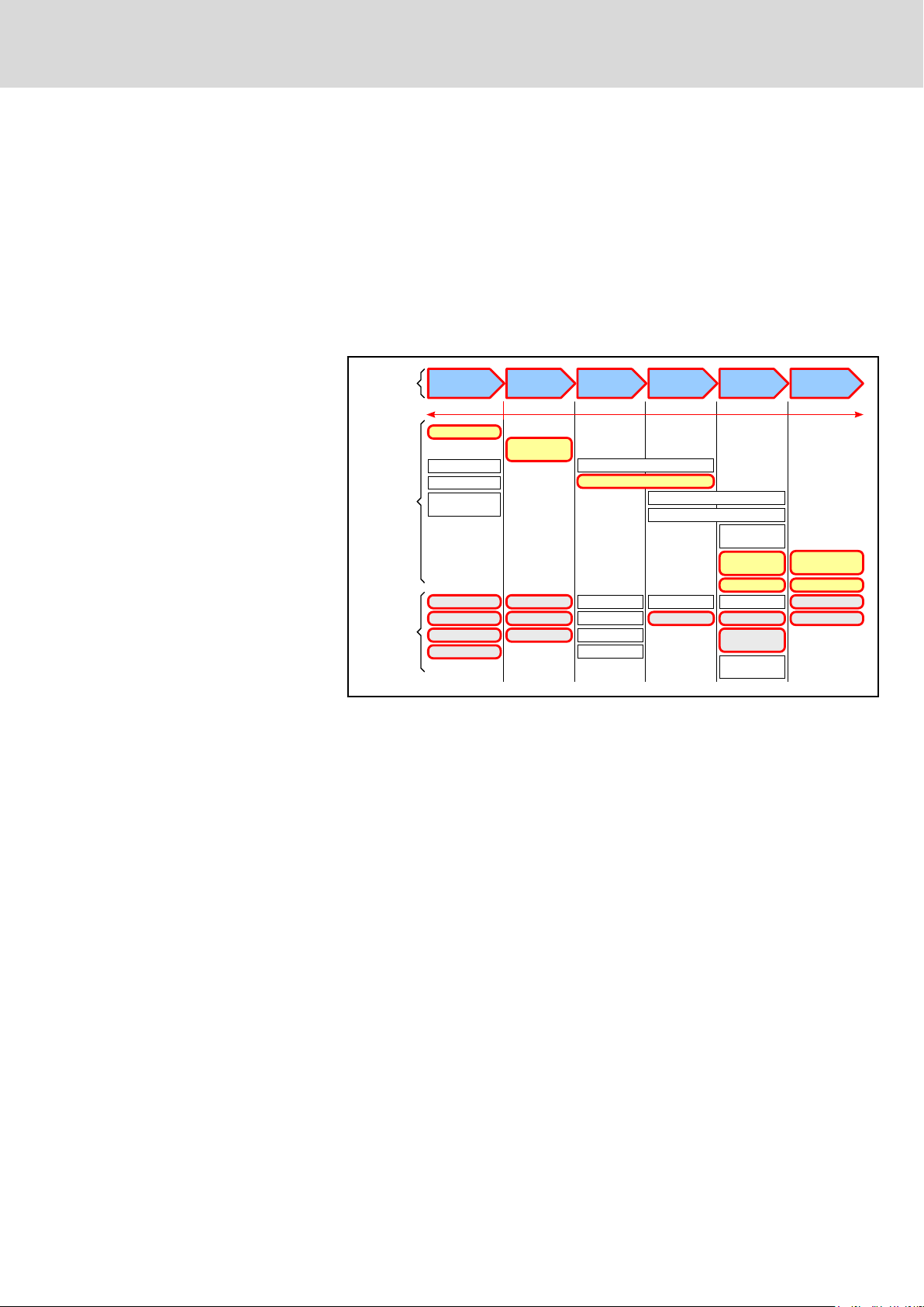
12.2 Switching times of the Y-repeater......................................................................................................... 36
12.2.1 Switching times without devices at the USB ports............................................................................. 36
12.2.2 Switching times with devices to the USB ports.................................................................................. 37
12.3 Display elements.................................................................................................................................. 37
12.4 Operating and error display.................................................................................................................. 37
13 Error causes and troubleshooting................................................................................ 39
14 Maintenance................................................................................................................ 41
14.1 Regular maintenance tasks.................................................................................................................. 41
15 Ordering information.................................................................................................... 43
15.1 Accessories and spare parts................................................................................................................ 43
15.2 Type code............................................................................................................................................. 43
16 Disposal....................................................................................................................... 45
16.1 Return................................................................................................................................................... 45
16.2 Packaging............................................................................................................................................. 45
17 Service and support..................................................................................................... 47
Index............................................................................................................................ 49
Bosch Rexroth AG DOK-SUPPL*-VAC*01*****-IT04-EN-PII/53
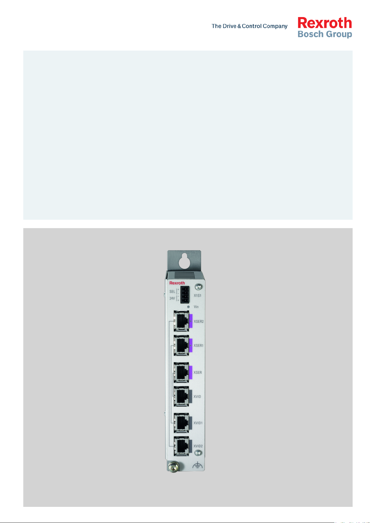
IndraControlVAC 01 Y-Repeater
Table of Contents