Bosch Rexroth APAS assistant K1100-10i User manual

Installation instructions
3 842 565 050/2019-11
Replaces: –
ENGLISH
APAS assistant K1100-10i
V01.00.00 - V01.00.99
3 842 562 910
ENGLISH

2/68
Bosch Rexroth AG, APAS assistant K1100-10i V01.00.00 - V01.00.99, 3 842 565 050/2019-11
The information in this manual is for product description purposes only. Any information in this manual on how to use the product only
constitute examples and recommendations. Catalog information is not binding. The information given does not exempt the user from
the obligation of own judgment and verication. Our products are subject to natural wear and aging.
© All rights reserved by Bosch Rexroth AG, also for the registration of industrial property rights. This document may not be reproduced
or distributed to third parties without our consent.
An example conguration is shown on the title page. The delivered product may thus vary from the illustration.
The original installation instructions are in German.
DE Die vorliegende Montageanleitung ist in den hier angebenen Sprachen verfügbar. Weitere Sprachen auf Anfrage.
Als gedruckte Version oder als PDF-Datei zum Download aus dem Medienverzeichnis:
www.boschrexroth.com/medienverzeichnis
Geben Sie in die Suchmaske (oben rechts, unter „Suche“) 3 842 563 137 ein, dann klicken Sie auf „Suche“.
EN These installation instructions are available in the languages shown here. Additional languages are available on request.
As a printed version or as a PDF le for download from the Media Directory:
www.boschrexroth.com/medienverzeichnis
In the search screen form (at the top right, under „Search“), enter 3 842 565 050, then click „Search“.
3 842 563 137 APAS assistant K1100-10i V01.00.00 - V01.00.99 DE Deutsch
3 842 565 050 APAS assistant K1100-10i V01.00.00 - V01.00.99 EN English

3/68
3 842 565 050/2019-11 APAS assistant K1100-10i V01.00.00 - V01.00.99, Bosch Rexroth AG
3/68Contents
1 About this documentation 6
1.1 Validity of the documentation 6
1.2 Further documentation 6
1.3 Presentation of information 7
1.3.1 Safety instructions 7
1.3.2 Safety markings 8
1.3.3 Information symbols 8
1.3.4 Terms used 9
2 Safety instructions 10
2.1 About this section 10
2.2 Intended use 10
2.3 Improper use 11
2.4 Personnel qualications 11
2.4.1 System integrator 11
2.4.2 Person commissioning the sensor skin 12
2.4.3 Operator 13
2.4.4 Maintenance/service technician 13
2.5 Installed safety equipment 13
2.6 Personal protective equipment 13
2.7 Integrator responsibilities 14
2.8 Owner responsibilities 14
2.9 General safety instructions 15
2.10 Product-specic safety instructions 15
3 Product description 16
3.1 Scope of delivery 16
3.2 Product overview 17
3.3 Speed switch function (optional) 17
3.4 Safety functions 18
3.4.1 Approaching the robot arm 18
3.4.2 Discrete EMERGENCY STOP 19
3.4.3 Local EMERGENCY STOP 19
3.5 Exchange of signals with safety relevance 20
Contents
3.5.1 Signals between safety controller of
APAS assistant and robot controller 20
3.5.2 EMERGENCY STOP linking between safety controller of
APAS assistant and customer system controller 21
3.5.3 Incorporation of end effector EMERGENCY STOP into
safety controller of APAS assistant 21
3.5.4 Trigger of stop responses 22
ENGLISH

4/68
Bosch Rexroth AG, APAS assistant K1100-10i V01.00.00 - V01.00.99, 3 842 565 050/2019-11
4 Technical data 23
4.1 Robot arm data 23
4.1.1 Work area and permissible velocity 24
4.1.2 Stopping distance and stopping times 24
4.1.3 Bearing load 25
4.1.4 Effective range of the sensor skin 26
4.2 Robot controller data 27
4.3 Safety module data 28
4.4 Pneumatics and hose breakaway device 29
4.4.1 Pneumatics 29
4.4.2 Hose breakaway device 29
4.5 Connecting cables 30
4.6 Bus topology PROFINET/PROFIsafe 31
4.7 Precongured WorkVisual project 32
4.7.1 Catalog element KR 10 R1100-2 APAS 400 V 32
4.7.2 Safety controller 32
4.7.3 End effector 36
4.7.4 Option packages 36
4.8 Signals for signal lamp 37
4.9 Interface between customer controller and APAS assistant controller 37
5 Transport and storage 38
5.1 Transporting the product 38
5.1.1 Removing the robot arm 38
5.1.2 Transporting the robot arm 39
5.1.3 Transporting the robot controller 40
5.2 Storing the product 41
6 Assembly and installation 42
6.1 Ambient conditions 42
6.2 Mechanical interface 42
6.2.1 Installing the robot arm 43
6.2.2 Installing the hose breakaway device 44
6.2.3 Installing the safety module 46
6.2.4 End effector interface 46
6.3 Electrical interfaces 47
7 Commissioning 48
7.1 Setting up the sensor skin 48
7.2 Commissioning robot and controller 48
7.3 Operation without higher-level controller 49
7.3.1 Preparing submit interpreter 49
7.3.2 Preparing the I/O circuitry 49
7.3.3 Preparing the program 50
7.3.4 Starting the program 50
7.4 Operation with higher-level controller 51
7.4.1 Connecting the robot with the higher-level controller 51
7.4.2 Acknowledging errors, acknowledging EMERGENCY STOP 53
7.5 Diagnosis variables 54
7.5.1 Overview 54
7.5.2 Displayed statuses 55
7.6 Parameter PROFIsafe host diagnosis code 58
7.6.1 States of communication with transmission 58
7.6.2 Error states 58

5/68
3 842 565 050/2019-11 APAS assistant K1100-10i V01.00.00 - V01.00.99, Bosch Rexroth AG
8 Operation 59
8.1 Operating modes 59
8.1.1 Automatic-external operation 59
8.1.2 T1 operation 60
8.1.3 T2 operation 60
8.2 Decommissioning 60
8.3 Disposal 60
9 Servicing and repair 61
9.1 Maintenance instructions 61
9.2 Maintenance of robot arm 61
9.3 Maintenance of robot controller 62
9.4 Maintenance of safety module 63
9.5 Maintenance of hose breakaway device 63
10 Appendix 64
ENGLISH

6/68 About this documentation
Bosch Rexroth AG, APAS assistant K1100-10i V01.00.00 - V01.00.99, 3 842 565 050/2019-11
1 About this documentation
1.1 Validity of the documentation
This document applies to the following product:
• APAS assistant K1100-10i APAS
This documentation is addressed exclusively to system integrators
(see Personnel qualications on page 11) who integrate the product into
existing systems. The installation instructions provide information about the
proper installation and use of the product.
Read the entire installation instructions, especially section 2 "Safety instructions",
before using this product.
Please note the safety instructions and observe the statements in these
installation instructions.
These installation instructions are a part of the product and must be available
at any time. When selling the product, this documentation must be handed on.
1.2 Further documentation
To be able to integrate the product into existing systems, the following
documentation must be available in addition to these installation instructions,
which you must read thoroughly and ensure you have understood it.
Title Version/number
Operating instructions KR C4 smallsize-2
KUKA Roboter GmbH
V7.0
Operating instructions KR AGILUS-2
KUKA Roboter GmbH
V3.0
Specications KR AGILUS
KUKA Roboter GmbH
V1.1
Installation and operating instructions KSS 8.5 SI V6
Conguration of kinematics
KUKA Roboter GmbH
V2.0
Installation and operating instructions KUKA.SafeOperation 3.4
KUKA Roboter GmbH
V6.0
Installation and operating instructions AE Sheet Steel 1350.500
RITTAL GmbH & Co. KG
Electrical documentation
KUKA Roboter GmbH
Electrical documentation of APAS assistant K1100-10i
Bosch Rexroth GmbH
IndraLogic XLC IndraMotion MLC 14VRS
SafeLogic system overview
R911341695
IH PNIOAck PSDx S20 documentation

About this documentation 7/68
3 842 565 050/2019-11 APAS assistant K1100-10i V01.00.00 - V01.00.99, Bosch Rexroth AG
1.3 Presentation of information
Standardized safety instructions, symbols, terms and abbreviations are used so
that you can use this documentation to work quickly and safely with your product.
These are explained in the following sections to help you understand them better.
1.3.1 Safety instructions
This document includes safety instructions before a course of action or a required
action whenever there is a risk of injury or property damage. Be sure to observe all
described safety precautions. Safety instructions are set out as follows:
SIGNAL WORD
Type and source of danger!
Consequences of non-compliance
Measures to prevent danger
…
• Warning sign: points out the danger
• Signal word: indicates the severity of the danger
• Type and source of danger: indicates the type and source of the danger
• Consequences: describes the consequences of non-compliance
• Prevention: states how the danger can be avoided
Table 1: Types of risk according to ANSI Z535.6-2006
Warning sign, signal word Meaning
DANGER Indicates a hazardous situation that will result in severe
injury or death if not avoided.
WARNING Indicates a hazardous situation that may result in severe
injury or death if not avoided.
CAUTION Indicates a hazardous situation that may result in minor to
moderate injury if not avoided.
NOTICE Property damage: The product or the surrounding area
could get damaged.
ENGLISH

8/68 About this documentation
Bosch Rexroth AG, APAS assistant K1100-10i V01.00.00 - V01.00.99, 3 842 565 050/2019-11
1.3.2 Safety markings
In this documentation, and also on the machine if necessary, the following warning
signs are used for health and safety notices when there is a risk of injury.
Table 2: Meaning of the safety markings
Symbol Meaning
Hazard
Dangerous electrical voltage
Suspended load
No unauthorized entry
Use foot protection
Observe instructions
1.3.3 Information symbols
Table 3: Meaning of the information symbols
Symbol Meaning
If this information is not observed, the product cannot be used and/or
operated as designed.
Single, independent action
1.
2.
3.
Numbered steps:
The numbers indicate that the steps must be performed in order.

About this documentation 9/68
3 842 565 050/2019-11 APAS assistant K1100-10i V01.00.00 - V01.00.99, Bosch Rexroth AG
1.3.4 Terms used
These installation instructions use the following designations:
Designation Meaning
Stopping distance Stopping distance = reaction distance + braking distance.
The stopping distance is part of the danger area.
Stopping angle The stopping angle is the angle the robot will move through after
triggering of the stop signal until it comes to a complete stop.
Stopping time The stopping time is the time that will pass after triggering of the
stop signal until the robot comes to a complete stop.
APAS assistant Short name of APAS assistant K1100-10i
Outreach Outreach = distance (in %) between axis 1 and the intersection
point of axes 4 and 5 (brake test).
EE End effector
Danger area The danger area comprises the work area and the stopping
distances.
Adjustment referencing Adjustment referencing is used to check if the current position of
the robot and the additional axes matches a reference position.
KLI KUKA Line Interface: Connection to higher-level controller
infrastructure (PLC, archiving)
KRC KUKA Robot Control
m Mass of rated load and additional load on the arm.
Phi Rotation angle (in °) around the respective axis.
POV Program override (in %) = travel velocity of the robot. This value
can be entered into the controller and read via the smartPAD.
Robot General designation the APAS assistant and/or of APAS assistant
K1100-10i
HBD Hose breakaway device
Sensor skin Capacitive sensor system for operator detection.
Sensor skin segment Sensor skin of an axis segment
Safety module APAS assistant safety controller and analysis unit of the sensor
skin
SSKU Analysis unit of the sensor skin
smartPAD Handheld programming device for KR C4. The smartPAD features
all operating and display options required for the operation and
programming of the industrial robot.
TCP Tool Center Point
ENGLISH

10/68 Safety instructions
Bosch Rexroth AG, APAS assistant K1100-10i V01.00.00 - V01.00.99, 3 842 565 050/2019-11
2 Safety instructions
2.1 About this section
The product has been manufactured in accordance with the generally accepted rules
of current technology. Nevertheless, there is a risk of personal injury and property
damage if you do not read this section and follow the safety instructions in this
document.
Read this documentation carefully and completely before you start working with
the product.
Keep the documentation accessible to all users at all times.
Always include them when giving the product to a third party.
2.2 Intended use
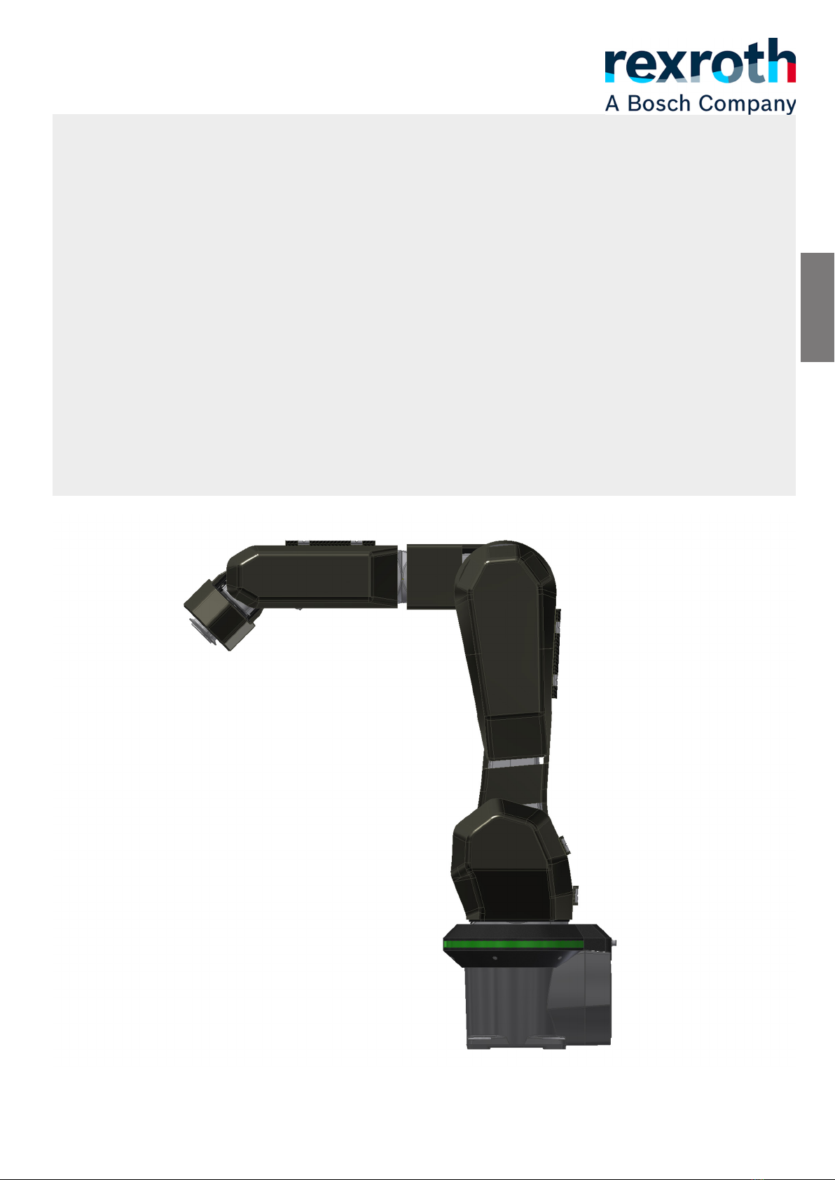
The APAS assistant K1100-10i is a robot system based on the industrial robot
KUKA Agilus KR10 R1100-2. The robot system is additionally equipped with
a capacitive sensor skin, an SRS and an SRS for collaborative operation. These safety
functions ensure that persons and detectable objects are detected safely and a safe
stop is triggered before a collision occurs. This makes safe human/robot collaboration
possible without a protective fence. The robot system constitutes a partly completed
machine and is exclusively intended for the following intended use:
• Independent performance of changing handling tasks with attached or gripped tools
in assembly as well as support of the operator in monotonous repetitive tasks.
• Installation on various substructures or in an existing system.
• Use exclusively in industrial applications and indoors.
• To prevent head and eye injuries,
– movements of the APAS assistant with adapted end effector, tool and gripped
workpiece, if applicable, are only permitted at a height less than 1.40 m above
all oors on which the personnel is standing, and
– work on the robot is only permitted when standing or walking upright.
• The exact ambient conditions in which the product may be used
(see Ambient conditions on page 42).
• The workpiece must be suitable for handling by the APAS assistant and for
collaborative operation. It must not have any points, cutting edges or similar
dangerous features.
• The product must be installed, set up, maintained and operated
according to these installation instructions and further documentation
(see Further documentation on page 6).
• The product may only be integrated, set up, maintained and
operated by an adult with the appropriate specialist knowledge
(see Personnel qualications on page 11).
• The product is strictly intended for professional use and not for private use.
The intended use also includes having read and understood these instructions,
especially section 2 "Safety instructions".

Safety instructions 11/68
3 842 565 050/2019-11 APAS assistant K1100-10i V01.00.00 - V01.00.99, Bosch Rexroth AG
2.3 Improper use
Any use other than that described in the section "Intended use" is considered
improper and is not permitted. Bosch Rexroth AG is not liable for any damage
resulting from improper use. The user alone bears any risks associated with
improper use. The following foreseeable misuses also constitute improper use:
• Use in explosive, medical environments or environments with strong
electromagnetic interference.
• Use with modied original protective equipment.
• Use in ESD and food areas, military or private use.
• Use with workpiece supports or workpieces not approved for operation.
• Use outside of the specied operation limits.
• Use outside of the permissible ambient conditions.
• Use for the transport of persons and animals.
• Use as a foot support.
• Assembly, connection, operation, handling and servicing of the product by
insufciently trained personnel.
Bosch Rexroth AG is not liable for any personal injury or property damage
resulting from improper use of the product.
For purchased parts and third-party makes incorporated into the product
see the manufacturer’s instructions and the supplied documentation
(see Further documentation on page 6) of the respective manufacturers.
2.4 Personnel qualications
The activities described in these installation instructions may only be performed by
authorized specialists.
2.4.1 System integrator
The system integrator is a trained specialist with knowledge in the following areas:
• Advanced knowledge of mechanical engineering
• Advanced knowledge of electrical engineering
• System knowledge of robot control
• Knowledge of sensor skin maintenance and commissioning.
Due to his/her training, knowledge and experience, the system integrator is able to
perform the following tasks:
• Incorporating the product into an existing system and adding an application to the
product.
• Detecting potential hazards during integration and dening suitable safety measures.
• Proper commissioning of the product.
• Programming and editing programs and automatic sequences.
• Troubleshooting, maintaining and servicing the product.
ENGLISH

12/68 Safety instructions
Bosch Rexroth AG, APAS assistant K1100-10i V01.00.00 - V01.00.99, 3 842 565 050/2019-11
For the work of the system integrator, the following mandatory training courses at
the BCI Training Center are required:
Designation Reference code
Basic course "Safe handling" [BCI-SP-AP031]
Advanced course "Sensor skin maintenance" [BCI-SP-AP015]
Advanced course "Preparation of work schedules" [BCI-SP-AP038]
Advanced course "Integration into projects" [BCI-SP-AP037]
You can nd an overview of the current training courses and training content
online at: https://www.bosch-apas.com/downloads/.
2.4.2 Person commissioning the sensor skin
The person commissioning the sensor skin is a trained specialist with the following
knowledge and skills:
• Sensor skin maintenance and commissioning
• Professional training in a technical eld
• Certicate of instruction in electrical engineering
Due to his/her training, knowledge and experience, the person commissioning the
sensor skin is able to perform the following tasks:
• Removal and installation of the sensor skin.
• Integration of additional sensor elements (e.g. optional collision detection element)
into the overall sensor skin.
• Parametrization of the sensor skin.
• Implementation of safety regulations for the operation of the sensor skin.
• Error detection and troubleshooting.
For the work of the person commissioning the sensor skin, the following
mandatory training courses at the BCI Training Center are required:
Designation Reference code
Basic course "Safe handling" [BCI-SP-AP031]
Advanced course "Sensor skin maintenance" [BCI-SP-AP015]
You can nd an overview of the current training courses and training content
online at: https://www.bosch-apas.com/downloads/.

Safety instructions 13/68
3 842 565 050/2019-11 APAS assistant K1100-10i V01.00.00 - V01.00.99, Bosch Rexroth AG
2.4.3 Operator
The operator has been instructed on the safe operation of the product in an
application and on potential dangers. After production release by the competent
safety specialist of the owner, the operator may perform the following tasks:
• Switching the product on and off.
• Start programs and automatic sequences.
2.4.4 Maintenance/service technician
The maintenance and service technician has been instructed on safe product
operation and product maintenance and troubleshooting.
The maintenance and service technician may perform the following tasks:
• Operating the product in manual mode.
• Programming and editing programs and automatic sequences.
• Troubleshooting, maintaining and servicing the product.
For the work of the maintenance/service technician, the following mandatory
training courses at the BCI Training Center are required:
Designation Reference code
Basic course "Safe handling" [BCI-SP-AP031]
Advanced course "Sensor skin maintenance" [BCI-SP-AP015]
Advanced course "Preparation of work schedules" [BCI-SP-AP038]
Advanced course "Integration into projects" [BCI-SP-AP037]
You can nd an overview of the current training courses and training content
online at: https://www.bosch-apas.com/downloads/.
2.5 Installed safety equipment
The APAS assistant has the following safety equipment:
• Sensor skin on axis segments 1-5 of the APAS assistant
• Sensor skin on the rotary union
• Robot controller
• Safety module: Analysis unit of the capacitive sensor skin, safety PLC for the APAS
assistant (PROFIsafe and discrete signals)
• Signal lamp to display the current state of the APAS assistant
• Handheld programming device (HPD) KUKA smartPAD with integrated
EMERGENCY STOP button
Additionally, the hose breakaway device for the use of pneumatic lines can be
installed. For further information see the hose breakaway device data on p. 25.
2.6 Personal protective equipment
The following protective equipment must be worn at all times:
• Protective goggles during setup operation (scope of delivery)
In the context of a specic application, safety risks can arise in collaborative
operation with the APAS assistant. These safety risks must be considered in
the risk assessment for this application and mitigated by accordingly derived
measures. These measures can include wearing further personal protective
equipment.
ENGLISH

14/68 Safety instructions
Bosch Rexroth AG, APAS assistant K1100-10i V01.00.00 - V01.00.99, 3 842 565 050/2019-11
2.7 Integrator responsibilities
The system integrator must comply with the following requirements:
Integrate the product according to the information in these
installation instructions and further relevant documentation
(see Further documentation on page 6).
Make sure that the national standards and regulations are complied with during
the installation of the product.
Perform a risk assessment according to EN ISO 12100 as amended for each
application in which the product is used. The product itself is a partly completed
machine, since the safety of the installation depends on the way the product is
integrated.
Design the application according to DIN EN 60204-1 and test the design.
Use safety functions and protective equipment.
If additional components (e.g. cables) not included in the scope of delivery of the
APAS assistant are integrated into it, they must not impair or disable any existing
safety functions.
Integrate the APAS assistant into the safety system of the overall system.
If the Ethernet safety interface is used, make sure that the overall system does
not pose any danger in an emergency. Shutting down the robot controller via the
Ethernet safety interface does not trigger an EMERGENCY STOP on the overall
system.
Prepare an EC declaration of conformity according to the Machinery Directive
for the overall system. The EC declaration of conformity is the basis for the
CE marking of the system.
Compile the technical documentation (operating and maintenance instructions,
vendor documentation, etc.) for the owner and their personnel.
Inform the owner about tasks they must perform according to these
installation instructions (e.g. denition of any maintenance cycles not yet dened).
Attach the CE mark in a visible location on the system.
Instruct the personnel on any existing residual risks.
2.8 Owner responsibilities
The owner must comply with and implement the following regulations:
• Ensuring proper use of the APAS assistant.
• Preparation of a hazard assessment for the workstation.
• Inspection of the protective equipment before starting work. The APAS
assistant must not be operated with deactivated or removed safety functions or
safety equipment.
• If the APAS assistant and the overall system share an EMERGENCY STOP circuit
and operating the overall system is possible even when the robot controller is
switched off, the smartPAD must either be covered or removed from the overall
system. This serves to prevent hazards resulting from a confusion of effective and
ineffective EMERGENCY STOP devices. Disconnected smartPADs must be removed
from the area around the overall system immediately.
• Enabling switches must not be permanently actuated with adhesive tape or other
tools or manipulated in any way.
• Instruction of the personnel at regular intervals.
• Monitoring duty and ensuring that there is sufcient space for the personnel to
move.
• Contacting the manufacturer in case of product safety defects.
• Checking that the personnel wears the personal protective equipment according to
the information in the installation and application instructions.
• Ensuring that any pinching and shear points which are not addressed in the
application-specic risk assessment are prevented.

Safety instructions 15/68
3 842 565 050/2019-11 APAS assistant K1100-10i V01.00.00 - V01.00.99, Bosch Rexroth AG
• Ensuring that no additional components are integrated in to the APAS assistant
which impair or disable the existing safety functions.
• Passwords for the KUKA System Software user groups must only be communicated
to authorized personnel.
2.9 General safety instructions
• As the owner, please note the following: before the initial commissioning of the
product, carry out a risk assessment in accordance with the national regulations in
your country (in Germany: according to the Occupational Health and Safety Act).
• As the distributing company/manufacturer of the machine, observe the following:
Before the initial commissioning of the machine, conduct a risk assessment in
accordance with DIN EN ISO 12100.
• Observe the applicable accident prevention and environmental protection
regulations.
• Observe the safety rules and regulations of the country in which the product is
being used.
• Only use Rexroth products that are in proper working order.
• Observe all the notices on the product.
• Persons who assemble, operate, disassemble or maintain Rexroth products should
not be under the inuence of alcohol, drugs or medication that may affect their
ability to respond.
• Use only original accessories and spare parts from Rexroth in order to prevent
hazards to people due to unsuitable spare parts.
• Observe the technical data and ambient conditions specied in the product
documentation.
2.10 Product-specic safety instructions
• Make sure that the EMERGENCY STOP button of the smartPAD is easily accessible
by the personnel at all times.
If the APAS assistant and the overall system share an EMERGENCY STOP circuit
and operating the overall system is possible even when the robot controller is
switched off, the smartPAD must either be covered or removed from the overall
system. This serves to prevent hazards resulting from a confusion of effective and
ineffective EMERGENCY STOP devices. Disconnected smartPADs must be removed
from the area around the overall system immediately
• Prior to working on the product:
– Secure a sufciently large work area.
– Inform the operating personnel and assign a supervisor.
– Observe the notices on the residual risk.
• Make sure that the product is only operated and monitored by personnel instructed
on the safety technology in operating modes T1 and T2.
• Do not touch any moving parts in automatic mode and test run mode.
• Do not modify or remove the protective panels.
ENGLISH

16/68 Product description
Bosch Rexroth AG, APAS assistant K1100-10i V01.00.00 - V01.00.99, 3 842 565 050/2019-11
3 Product description
The APAS assistant comprises all components of the KUKA KR 10 R1100-2 industrial
robot. The robot arm is additionally equipped with a capacitive sensor skin and safety
functions. The safety functions makes operation without a protective fence possible.
This makes safe human/robot collaboration possible. The APAS assistant stops as
soon as the sensor skin is triggered by an approaching person or object. The typical
switching distance is approx. 50 mm. As soon as the sensor range is free again, the
APAS assistant will automatically resume the motion sequence.
3.1 Scope of delivery
The following is included in the scope of delivery:
• APAS assistant K1100-10i robot arm (KUKA Agilus, KR 10 R1100-2) with sensor skin
and signal lamp
• Robot controller KUKA KR C4 smallsize-2
• Safety module
• Cable sets (see Connecting cables on page 30)
• Operating unit KUKA smartPAD Teach Pendant
• Transport device including clamp ring
• Hose breakaway device
• Protective goggles
• Installation instructions
• Further documentation (see Further documentation on page 6)
• Packaging
Should you require options after delivery, please contact Bosch Rexroth AG.

Product description 17/68
3 842 565 050/2019-11 APAS assistant K1100-10i V01.00.00 - V01.00.99, Bosch Rexroth AG
3.2 Product overview
1 Robot arm with sensor skin
2Handheld programming device KUKA smartPAD with EMERGENCY STOP button
3 Safety module: Analysis unit of the capacitive sensor skin, safety PLC for the
APAS assistant (PROFIsafe and discrete signals)
4 KUKA robot controller
5 Signal lamp to display the operating statuses
6 Rotary union
7 Hose breakaway device
3.3 Speed switch function (optional)
With the speed switch function, the workspace of the APAS assistant is monitored
by safety sensors installed by the customer. If a person moves into the monitoring
range of the safety sensors, the permissible velocity is switched from speed
velocity to collaboration velocity. The robot delay is safely monitored. It the robot
does not reach the collaboration velocity within the expected time, a safety stop
1 is triggered. The collaboration speed is safely monitored as long as a person is
detected by the safety sensors.
When the safety sensors installed by the customer report that there are no persons
in the danger area for speed velocity, the safe velocity monitoring for collaborative
operation is deactivated and the APAS assistant can be returned to speed velocity by
the customer.
2
1
7
3
4
6
5
ENGLISH

18/68 Product description
Bosch Rexroth AG, APAS assistant K1100-10i V01.00.00 - V01.00.99, 3 842 565 050/2019-11
3.4 Safety functions
The integrator must
• connect the end effector to the safety controller,
• connect the system controller with the robot controller, and
• link the safety controller with the EMERGENCY STOP circuit of the system.
The system integrator must achieve the performance level resulting from the
respective risk graph in the risk assessment for all application-specic safety
functions.
Notices regarding the safety functions of the robot controller can be found in
the KUKA operating instructions KUKA KR C4 smallsize-2
(see Further documentation on page 6).
Sections 3.4.1 to 3.4.3 list specic safety functions of the
APAS assistant K1100-10i.
3.4.1 Approaching the robot arm
Safety function Achieved
performance level
PFHD [1/h]
Operator approaching the robot arm PL d 6,6E-7
The sensor skin is used to monitor the area around the robot arm.
Upon approaching the sensor skin (typical triggering distance approx. 50 mm),
the safety stop 1 with automatic restart is triggered. As soon as the trigger range of
the sensor skin is free again, the robot system will restart automatically.
The sensor skin requires application-specic teaching in.
Customer APAS assistant K1100-10i V01.00.XX
System
controller
Ethernet
safety
interface
EMERGENCY
STOP linking,
discrete
Robot
controller
Sensor skin
+ SSKU
PROFINET /
PROFIsafe Discrete Discrete
Safety controller
End effector

Product description 19/68
3 842 565 050/2019-11 APAS assistant K1100-10i V01.00.00 - V01.00.99, Bosch Rexroth AG
3.4.2 Discrete EMERGENCY STOP
Safety function Achieved
performance level
PFHD [1/h]
Discrete EMERGENCY STOP PL d 1,4E-7
Discrete EMERGENCY STOP is triggered by
• Externally triggered customer EMERGENCY STOP on discretely wired safety circuit
• Determined diagnosis error of the safety PLC
• Determined diagnosis error during self-diagnosis of the sensor skin
• EMERGENCY STOP by end effector
In case of a discrete EMERGENCY STOP, the safety stop 1 without automatic restart
is triggered.
The cause of the error must be determined and remedied before a restart can be
performed.
The triggering EMERGENCY STOP device, e.g. at the end effector, must comply
with the following requirements in order to achieve the performance level of the
safety function stated above:
• Discrete I/Os, two-channel redundant, NC priority controlled
• Contacts are oating
• The EMERGENCY STOP device achieves a B10D value of 100,000 cycles
per channel, corresponding to the typical component values for an
EMERGENCY STOP system as per IEC 60947 and ISO 13850.
• Maximum demand rate ≤ 3840 cycles per year or MTTFd ≥ 260.4 a
3.4.3 Local EMERGENCY STOP
Safety function Achieved
performance level
PFHD [1/h]
Local EMERGENCY STOP PL d 2E-7
A local emergency stop is triggered when the robot system signals a local
emergency stop. The safety function is used to interrupt electrical or safety circuits
in application-specic actuators which are connected to the robot system.
When a local emergency stop is triggered, actuators in the periphery of the
APAS assistant K1100-10i are moved into their respective safe state. Since the
safe states are only known to the system integrator, he/she is required to put these
actuators into a safe state.
The cause of the error must be determined and remedied before the actuator may
leave its safe state.
Actuators in the periphery which are included in this safety function must fulll the
following requirements to achieve the performance level stated above:
• suitable for PL d
• PFHd ≤ 1E-7 1/h
• Relays with two assigned channels on the input side, with priority-controlled,
oating auxiliary contacts
ENGLISH

20/68 Product description
Bosch Rexroth AG, APAS assistant K1100-10i V01.00.00 - V01.00.99, 3 842 565 050/2019-11
3.5 Exchange of signals with safety relevance
3.5.1 Signals between safety controller of APAS assistant and robot controller
The following signals with safety relevance are exchanged via the Ethernet safety
interface PROFIsafe between the safety controller of the APAS assistant and the
robot controller.
Signal direction PROFIsafe byte PROFIsafe bit English description
KRC -> PLC-R 0 0 Local EMERGENCY STOP
from KRC
KRC -> PLC-R 0 6 Operating mode T1
KRC -> PLC-R 0 7 Operating mode T2
KRC -> PLC-R 1 6 Safety interface active
KRC -> PLC-R 2 0 Safety option active
PLC-R -> KRC 0 0 Reserved 1
PLC-R -> KRC 0 1 Input for external
EMERGENCY STOP
PLC-R -> KRC 0 2 Operator protection/
sensor skin triggered
PLC-R -> KRC 0 4 Safety STOP 1 (all axes)
PLC-R -> KRC 0 5 Safety STOP 2 (all axes)
PLC-R -> KRC 1 0 US2 supply voltage
PLC-R -> KRC 1 1 Safe operating stop
(all axes)
PLC-R -> KRC 1 2 Reserved 11
PLC-R -> KRC 1 3 Reserved 12
PLC-R -> KRC 1 4 Reserved 13
PLC-R -> KRC 1 5 Reserved 14
PLC-R -> KRC 1 6 Reserved 15
PLC-R -> KRC 3 0 Reserved 25
PLC-R -> KRC 3 1 Reserved 26
PLC-R -> KRC 3 2 Reserved 27
PLC-R -> KRC 3 3 Reserved 28
PLC-R -> KRC 3 4 Reserved 29
PLC-R -> KRC 3 5 Reserved 30
PLC-R -> KRC 3 6 Reserved 31
PLC-R -> KRC 3 7 Reserved 32
PLC-R -> KRC 5 15 Monitoring space 14 /
axis angle limitation
space
PLC-R -> KRC 5 15 Monitoring space 15 /
Collaboration room
PLC-R -> KRC 5 16 Monitoring space 16 /
Speed space
PLC-R -> KRC 6 0 Tool 1
Table of contents
Other Bosch Robotics manuals