results in very high continuous SPL
capability and superior low frequency
output without the need for external
limiters/compressors. The OC-1 is supplied
with a cable which is used to sense the
output voltage of the amplifier for AWCS II
system.The cable must be connected to
the four pin DIN connection on the rear
panel of the systems controller and the
amplifier output for the AWCS II system.
The system will automatically mute after
approximately one minute if this connec-
tion is not made.
The Bose®Acoustic Wave®CannonTM
System II loudspeaker provides a flexible,
building-block approach to meet the sound
reinforcement requirements of a wide variety
of applications. You will find detailed
installation and system design guidelines
in the Bose®Acoustic Wave®CannonTM
System II Loudspeaker Owner’s Guide.
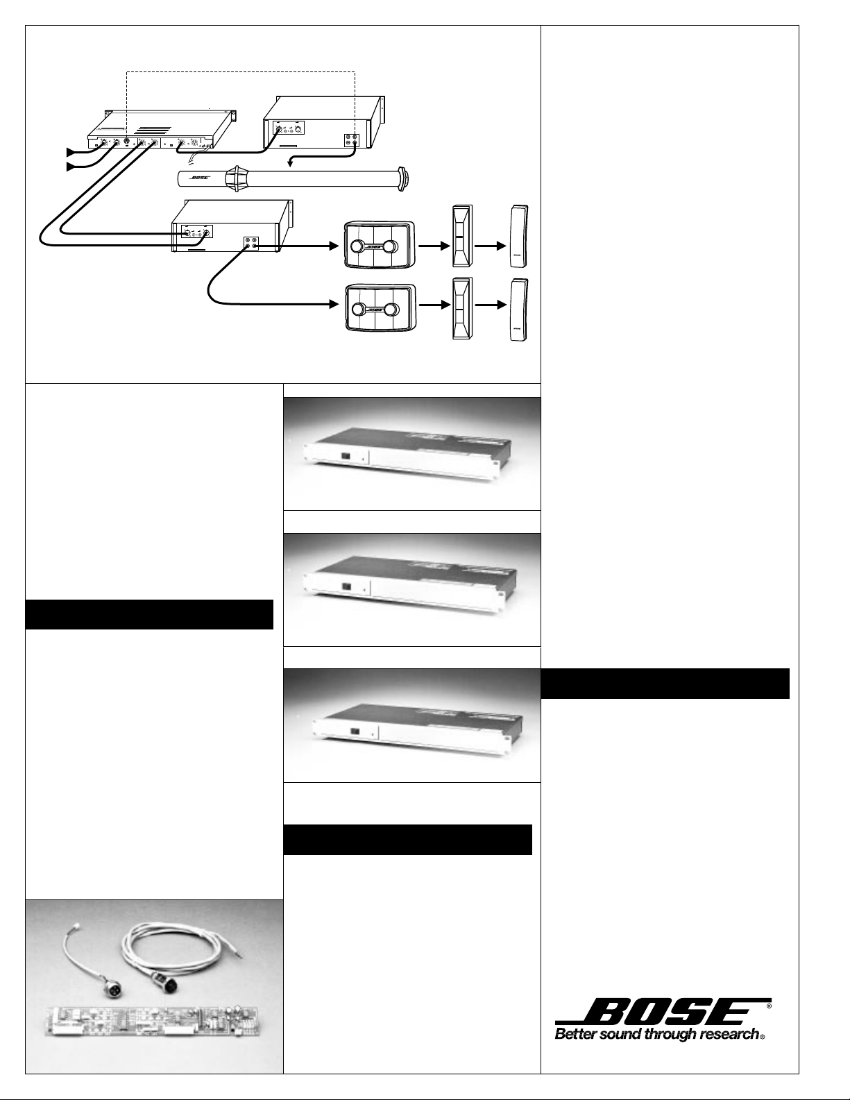
Figure 1 shows three possible system
configurations: one AWCS II loudspeaker,
two 802®, 402TM, or 502TM loudspeakers,
and the appropriate systems controller.
Figure 2 shows the OC-1 option card to
be installed in the systems controller.
Figure 3 a, b, c shows the 402C, 502C
and 802C Series II systems controllers.
Figure 1
© 1995 Bose Corporation, The Mountain, Framingham, MA
01701-9168 USA JN94899 PN177920-Rev. 2
Architects’ Specifications
The maximum acoustic output of the
bass enclosure shall be 115dB-SPL
from 25Hz to 125Hz, with measurements
referenced to a full-bandwidth pink-noise
input at 1 meter at the enclosure’s rated
power. Its power handling capacity shall
be 300 Watts continuous, referenced to
IEC noise for 100 hours.
The enclosure shall be made of custom
extruded polyvinyl chloride pipe. Outer
dimensions of the enclosure shall be 150"
(L) x 17" (W) (3.81 x .43 m); its weight
shall be 63 lb (29 kg).
The low-frequency device shallbe the
Bose®Acoustic Wave®CannonTM
System II loudspeaker.
The AWCSTM II system shall be provided
with a separate system controller, to be
connected before the input(s) of the
sys-
tem power amplifier(s). An OC-1 option
card, installed in the systems controller,
shall replace the bass active equalization.
The fixed, 2-channel system controller
shall provide active electronic equaliza-
tion and crossover functions. It shall in-
clude an operating mode switch, input
sensitivity switch, low-frequency output
level control, and mono sum switch. The
system controller shall use screw-type
terminal strips for balanced input and
output wiring connections. Outer dimen-
sion of the systems controller shall be
1.75" (H) x 19.0" (W) x 8.0" (D) (4.4 x
48.3 x 20.3 cm). It shall fit in the single
space of a standard 19" equipment
rack for mounting. Its weight shall be
5.5 lb (2.5 kg).
The electronic controller shall be the
Bose 402TMC, 502TMC or 802®C Series II
systems controller.
The Bose Acoustic Wave®Cannon
System II (AWCS II) loudspeaker is
covered by a 5-year, transferable
limited warranty. The Bose 402C 502C
and 802C Series II systems controllers
are covered by a 2-year, transferable
limited warranty.
Figure 2
INPUTB
INPUTB INPUTA
BRIDGE
INPUTA
220 V
~
MADEIN USA
CAUTION
Inorder to grant a secure operation do not mount the amplifier in
afully closed housing. To preven electric shock, do not remove
cover.Disconnect power line in case of servicing.
ACHTUNG:
Umsichere Funktion zu gewährielsten, Gerät nicht in vollständig
geshlossenesGehäuse einbauen. Abdeckung während des
Betriebesnicht entfernen. Bor Offnen des Gerätes Netzstecker
ziehen.
BoseCorporation, Framingham 01701, Mass, U.S.A.
SerialNo.:
Madein Germany
0
.
.
.
.
.
.
.
+3
-18
INPUTLEVEL
–10 +4
INPUT
INPUTLEVEL
–10 +4
MODE
OPT4
1
2
NC3
HIGH
FREQ
OUTPUT LOWFREQ
LEVEL
OUTPUTMODE
NORMSUM
LOW
FREQ
OUTPUT
CH1/SUM CH 2
230V
~
AC
50/60Hz 12W
PIN1 GRN
PIN2 +
PIN3 –
PROTECTEDBYU.S. PATENT 3,038,964
CH 2CH 1
PIN1 GRN
PIN2 +
PIN3 –
BA FR
CH 2
PIN1 GRN
PIN2 +
PIN3 –
CH 1
REFERTO YOUR INSTRUCTION MANUAL FOR PROPER INSTALLATION
ANDOPERATING PROCEDURES. INCORRECT WIRING MAY RESULTIN
DAMAGEAND/OR POOR PERFORMANCE.
CAUTION AVIS
RISKOF ELECTRICAL SHOCK
DONOT OPEN RISQUE DE CHOC ELECTRIQUE
NEPAS OUVRIR
WARNING:
TOREDUCE THE RISK OF FIRE OR ELECTRICAL SHOCK
DONOT EXPOSE THIS EQUIPMENT TO RAIN OR MOISTURE.
MODE SWITCH GUIDE
POSITION OPERATINGMODE
4
2-WAYWITH LOW FREQUENCY OPTION
(NOTUSED)
3
STANDARD2-WAY(WITH 502B)
2
VOICEONLY/FULL RANGE (WITH 502A)
1
geprüdfte
Sicherheit
TÜVRheinland
INPUTB
INPUTB INPUTA
BRIDGE
INPUTA
220 V
~
MADEIN USA
CAUTION
Inorder to grant a secure operation do not mount the amplifier in
afully closed housing. To preven electric shock, do not remove
cover.Disconnect power line in case of servicing.
ACHTUNG:
Umsichere Funktion zu gewährielsten, Gerät nicht in vollständig
geshlossenesGehäuse einbauen. Abdeckung während des
Betriebesnicht entfernen. Bor Offnen des Gerätes Netzstecker
ziehen.
BoseCorporation, Framingham 01701, Mass, U.S.A.
SerialNo.:
Madein Germany
®
®
®
®®
®®
AWCS™II
802® 402™502™
System Configurations
The low frequency device shall be a light-
weight double barrel enclosure that uses
two waveguides as the acoustic vehicle.
The transducer shall consist of one (1)
woofer of 12" (30 cm) diameter, mounted
between the flanges that join the two
waveguides. The waveguide design of
the barrel shall limit cone excursion to
1" (.4 cm) p-p, to reduce distortion. The
operating frequency range shall be 25Hz
to125Hz.The input connector, located on
the driver flange of the short barrel, shall
be 2-conductor spade lugs (barrier strips).
402C Controller
Figure 3a
Figure 3b 502C Controller
Figure 3c
Warranty Information
802C II Controller


