manuals.online logo
Brands
  1. Home
  2. •
  3. Brands
  4. •
  5. Boss Audio Systems
  6. •
  7. Car Stereo System
  8. •
  9. Boss Audio Systems MR1309UAB User manual

Boss Audio Systems MR1309UAB User manual

Other manuals for MR1309UAB

1

Other Boss Audio Systems Car Stereo System manuals
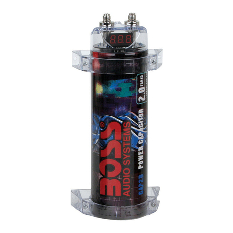
Boss Audio Systems CAP2B User manual

Boss Audio Systems

Boss Audio Systems CAP2B User manual
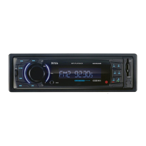
Boss Audio Systems 625UAB User guide

Boss Audio Systems

Boss Audio Systems 625UAB User guide
Boss Audio Systems 638BA User manual

Boss Audio Systems

Boss Audio Systems 638BA User manual

Boss Audio Systems 625UAB User manual

Boss Audio Systems

Boss Audio Systems 625UAB User manual

Boss Audio Systems RDS738BI User manual

Boss Audio Systems

Boss Audio Systems RDS738BI User manual

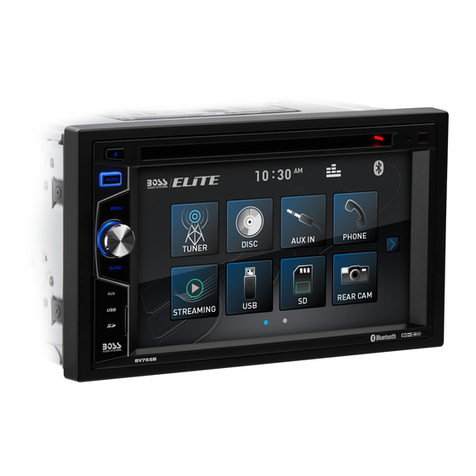
Boss Audio Systems ELITE BV755B User manual

Boss Audio Systems

Boss Audio Systems ELITE BV755B User manual

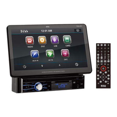
Boss Audio Systems BVS10.1 User manual

Boss Audio Systems

Boss Audio Systems BVS10.1 User manual

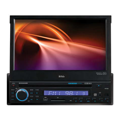
Boss Audio Systems BV9968BI User manual

Boss Audio Systems

Boss Audio Systems BV9968BI User manual

Boss Audio Systems BVML500 User manual

Boss Audio Systems

Boss Audio Systems BVML500 User manual

Boss Audio Systems 611UAB User manual

Boss Audio Systems

Boss Audio Systems 611UAB User manual

Boss Audio Systems 865DBI User manual

Boss Audio Systems

Boss Audio Systems 865DBI User manual
Boss Audio Systems 508UAB User manual

Boss Audio Systems

Boss Audio Systems 508UAB User manual

Boss Audio Systems BV6654B User manual

Boss Audio Systems

Boss Audio Systems BV6654B User manual

Boss Audio Systems 628UA User manual

Boss Audio Systems

Boss Audio Systems 628UA User manual

Boss Audio Systems 632UAB User manual

Boss Audio Systems

Boss Audio Systems 632UAB User manual

Boss Audio Systems 632UAB User manual

Boss Audio Systems

Boss Audio Systems 632UAB User manual

Boss Audio Systems BV6658B User manual

Boss Audio Systems

Boss Audio Systems BV6658B User manual

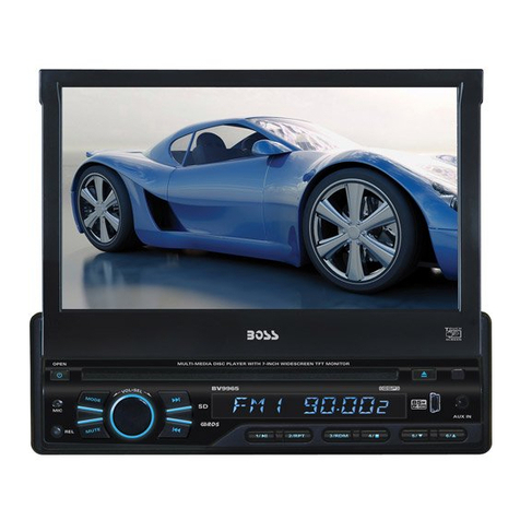
Boss Audio Systems BV9965 User manual

Boss Audio Systems

Boss Audio Systems BV9965 User manual

Boss Audio Systems BV9985 User manual

Boss Audio Systems

Boss Audio Systems BV9985 User manual

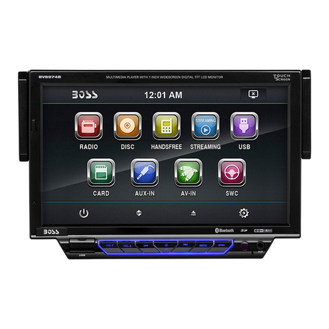
Boss Audio Systems BV8974B User manual

Boss Audio Systems

Boss Audio Systems BV8974B User manual

Boss Audio Systems MR50W User manual

Boss Audio Systems

Boss Audio Systems MR50W User manual
Boss Audio Systems CAP2C User manual

Boss Audio Systems

Boss Audio Systems CAP2C User manual
Popular Car Stereo System manuals by other brands

Sony CDXM60UI - Marine CD Receiver MP3/WMA/AAC... Features

Sony

Sony CDXM60UI - Marine CD Receiver MP3/WMA/AAC... Features

Philips CED780/98 quick start guide

Philips

Philips CED780/98 quick start guide

Becker Online Pro 7800 installation guide

Becker

Becker Online Pro 7800 installation guide

JVC KD-LH810 instructions

JVC

JVC KD-LH810 instructions

Clarion PU-9836A Service manual

Clarion

Clarion PU-9836A Service manual

Sony RM-X7BT reference guide

Sony

Sony RM-X7BT reference guide

Mitsubishi Electric AR0M manual

Mitsubishi Electric

Mitsubishi Electric AR0M manual

Insignia NS-HD5113 user guide

Insignia

Insignia NS-HD5113 user guide

Clarion BTD3341 user manual

Clarion

Clarion BTD3341 user manual

USA SPECS PA11-VW6 owner's manual

USA SPECS

USA SPECS PA11-VW6 owner's manual

Sony MEX-N4380BT operating instructions

Sony

Sony MEX-N4380BT operating instructions

Kenwood KCD-BT6544U/UY Service manual

Kenwood

Kenwood KCD-BT6544U/UY Service manual

JVC KD-DB912BT instruction manual

JVC

JVC KD-DB912BT instruction manual

Philips CSQ405/98 user manual

Philips

Philips CSQ405/98 user manual

Alpine TDM-7544 Specifications

Alpine

Alpine TDM-7544 Specifications

JL Audio Stealthbox SB-CAN-G2MVX3D/10TW3 installation guide

JL Audio

JL Audio Stealthbox SB-CAN-G2MVX3D/10TW3 installation guide

Denso TEN FT0108A user manual

Denso TEN

Denso TEN FT0108A user manual

Pyle PLD57MU owner's manual

Pyle

Pyle PLD57MU owner's manual

manuals.online logo
manuals.online logoBrands
  • About & Mission
  • Contact us
  • Privacy Policy
  • Terms and Conditions

Copyright 2025 Manuals.Online. All Rights Reserved.

USER'S
MANUAL
MR1309UAB
8LUETOOTH®-ENABLED
FULLY
MARINIZED
MP3-COMPATIBLE
DIGITAL
MEDIA
RECEIVER
WITH
USB
AND
SO
MEMORY
CARD
PORTS
AND
FRONT
PANEL
AUX
INPUT
~;
t::lt I \1 T
t\
I
·.~~
:::
,
''-'
1\
J_
, ,,
:::
-- --
==!-··~
;-·-===
DETACHABLE
FACE
®
INSTRUCTION
MANUAL
CAR RADIO RECEIVER I
MP3
PLAYER
WITH BULETOOTH HAND FREE SYSTEM
TUNING
I
SEEK
UP/DOWN
NEXT/ BACK BUTTON
~
A~.i-
r
~~··I
:::::
,--
'
-=:
--·
--·
LCD
DISPLAY
::.-:.419--\.
---
~
TALK CANCEL/ ENCODER
VOLUME
KNOB
MENU
BUTTON PLAY/ INTRO REPEAT RANDOM UP/DOWN
BUTTON SRC
POWER/
MUTE
BUTTON
BUTTON
AMS
BUTTON AUDIO
SELECT
BUTTON
PAUSE SCAN BUTTON BUTTON BUTTONS
BUTTON BUTTON
~
~~.i-
,
~~~.·
I
:::::
,--
i
-=:
.
--·
--·
::.-:.
4!9
--
\.
---
~
BAND INFRARED
BUTTON REMOTE
SENSOR
PRESET MEMORY STATION BUTTONS
(M1-M6)
,..----~--
TALK BUTTON
POWER BUTTON
----+----+-:
H---+----
MUTE BUTTON
VOLUME
UP
I
DOWN BUTTONS
···················
·
'14---+---
BAND BUTTON
~--=--+---
AUDIO BUTTON
DISP
BUTTON
~~~~-+---
TUNING
I
SEEK/ MP3 TRACK UP/DOWN BUTTON
'lli-+---t---
AMS BUTTON
..........,,..,.,.,.,..,.....,......+---
INTRO SCAN BUTTON
EQ
BUTTON
----+--+
LOUD BUTTON
----t-----=~
!:!..±1--t---
REPEAT BUTTON
·················PRESET
MEMORY BUTTONS
'----=----+--10+/-
FOLDER UP/DOWN BUTTONS
'~'-+--+---
DISP BUTTON
REMOTE CONTROL
INSTALLATION
• Before final installation,
connect
the wiring temporarily and make sure it is all working
properly.
• Use only the parts included with the unit to ensure proper installation. The use
of
unauthorized parts can cause malfunctions.
• This item must be installed
by
an authorized dealer in order
to
keep the warranty vaild.
• Install the unit where it
does
not get in the driver•s way and cannot injure the passenger if
there is a sudden stop, like an emergency stop.
• Avoid installing the unit where it would be subject
to
high temperature, such as direct
sunlight, or hot air, heater
or
where it would be subject
to
dust
dirt
or
excessive vibration.
• Be sure to remove the front panel before installing the unit.
DIN FRONT/REAR-MOUNT
This unit can be property installed either from Front (conventional DIN Front-mount) or Rear
(DIN Rear-mount installation, utilizing threaded screw holes at the sides
of
the unit chassis).
For details, refer to the following illustrated installation
methods
A and
B.
-DIN FRONT-MOUNT (Method
A}
Installation the unit
1
Removing the unit
a
c
1. Dashboard
2.
Holder
After inserting the half sleeve into the
dashboard, select the appropriate tab
according
to
the thickness
of
the
dashboard material and bend them
inwards
to
secure the holder in place.
a.
Frame
b. Insert fingers into the groove in the
front
of
frame and pull out to remove
the frame. (When re-attaching the
frame, point the side with a groove
down
wards and attach it.)
c.
Insert the levers supplied with the
unit into the grooves at both sides
of
the unit as shown in figure until they
click. Pulling the levers makes it
possible
to
remove the unit from the
dashboard.
E-2
-DIN REAR-MOUNT (METHOD
B)
Installation usingthe screwholesonthe sides ofthe unit.
Fasteningthe unittothefactory radio mounting bracket.
4
1. Select a position where the screw
holes ofthe bracket and the screw
holes of the main unit become
aligned (are fitted) and tighten the
screws at 2 places on each side.
2.
Screw
3.
Factoryradio mounting bracket.
4.
Dashboard orConsole
5.
Hook
(Removethis part)
Note: the mounting box, outer trim ring,
and half-sleeve are not used for method
B installation.
2. DETACHABLE
CONTROL
PANEL (D.C.P.)
Removing The Detachable Control Panel (D.C.P.).
PANEL RELEASE
BUTION
Attaching the DCP
CAUTION
1.
Turn the power off
2.
Press the
D.C.P.
release button
3.
Remove the
D.C.P.
1. Attach the panel at the right side first, with
point B on the main unit touching point A on
the
D.C.P.
(As shown on the diagram).
2.
Then press the left side of
D.C.P.
onto the
main unit until a click sound
is
heard.
• DO NOT insert the D.C.P from the left side. Doing so may damage it.
• The D.C.P can easily be damaged
by
shocks. After removing it, place it in a protective case
and be careful not to
drop
it or subject it to strong shocks.
• When the release button is pressed and the D.C.P
is
unlocked, the car•s vibrations may
cause it to fall. To prevent
dam~e
to
the
D.C.P,
always store it in a protective case after
detaching
it.
• The rear connector that connects the main unit and the D.C.P
is
an extremely important
part. Be careful not to damage it by pressing on it with fingernails, pens, screwdrivers, etc.
Note:
If the D.C.P is dirty, wipe off the dirt with soft, dry cloth
only. And use a cotton swab soaked
in
isopropyl
alcoholto clean thesocketon the backofthe
D.C.P.
E-3
DETACHABLE
CONTROL
PANEL (D.C.P.)
Removing The Detachable Control Panel
(D.C.P.).
D.C.P.
Attaching the Detachable Control panel (D.C.P.)
r
2.
CAUTION
1.
Turn the Power off.
2.
Press the Panel Release Button.
3.
Remove the D.C:P
1.
Insert the right side of the
D.C.P.
Into
the main unit.
NOTE: The
D.C.P.
Must be attached into
the T-Joint.
2.
Press the
D.C.P.
On to the left side
of
middle of
D.C.P.
Until a click sound is
heard.
• DO NOTinsertthe D.C.Pfromthe leftside. Doing so may
damage
it.
• The D.C.P can easily be
damaged
byshocks. After removing it, place it
in
a protectivecase and
be careful notto
drop
it
or
subjectitto strong shocks.
• Whenthe release button is pressed and the D.C.P is unlocked, the car's vibrations maycause it
to
fall. To preventdamage
to
the
D.C.P,
alwaysstore it in a protectivecase afterdetaching
it.
• The rear connectorthatconnectsthe main unitand the D.C.
Pis
an extremely importantpart. Be
careful not
to
damageit
by
pressing on it with fingernails, pens, screwdrivers, etc.
Note:
If the D.C.P is dirty, wipe off the dirt with soft,
dry
cloth only. And use a cotton swab soaked
in isopropyl alcohol to clean the socket on the
back
of
the
D.C.P.
E-4
ELECTRICAL CONNECTION
a.
Make sure
your
car battery
is
a 12 volt negative ground system.
b.
Before starting wiring connections, disconnect the power
supply
by removing the fuse
from the fuse box.
c.
Connect the power wire to one of the extra terminals ofthe fuse box.
d. Connect the black ground wire to a metal part of the car. It is important
to
make
good
contact.
e.
Make other wiring connections as shown.
f.
If
your
car does not have ISO connector, you can procure it from any car accessory shop.
Notes: INCORRECT WIRING OR OPERATION WILL VOID THE WARRANTY OF THIS UNIT.
Fuse
Replacement:
ELECTRICAL CONNECTION
To replace the fuse, pull out
tt"e
blown fuse from the socket. Insert
REAR
a new one with same rating
REAR RIGHT SPEAKER
m
rn
(-)
(+)
MEMORY +12 V FRONT RIGHT SPEAKER
m m
rn
(-)
(+)
REM
TRIGGER
+12
v
FRONT LEFT SPEAKER
ITJ
[I]
DJ
(-)
(+)
GROUND ACC REAR LEFT SPEAKER
mm mm
+12
v
(-)
(+)
SIDE A SIDE B
4
YELLOW
1
VIOLET
5
BLUE
2
VIOLET/BLACK
7
RED
3
GREY
8
BLACK
4
GREY/BLACK
5 WHITE
6
WHITE/BLACK
7 GREEN
8
GREEN/BLACK
ANTENNA
,_____
___
LINE OUT FRONT
WHITE (L)
RED (R)
HARNESS
POWER(+)
RED
+
12
V
YELLOW
(FUSED
MEMORY
GND
r---_B_L_A_C_K____.
LEFT
SP.
FRONT
-
GREEN/BLACK
+
WHITE
-
WHITE/BLACK
BLUE
AUTO
ANT.
VIOLET
+
VIOLET/BLACK
-
GREY
+
GREY/BLACK
GENERAL OPERATION
POWER
ON/OFF
BUTTON (
CD
)
REAR
RIGHT
SP.
FRONT
Press POWER button or any other button on the front ofthe radio to turn the unit on.
Press POWER button briefly to turn the unit off.
MUTE BUTTON
Press the mute button momentarily to mute the audio volume, and
11
Mute
11
will
in
the
display. Press the mute button again to restore volume to the previous setting.
AUDIO
SELECT BUTTON {ROTARY VOLUME
CONTROL
KNOB)
Pressthis buttonto selectdesired audiofunction.
VOLUME
{VOL)->BASS
{BAS)->TREBLE
{TRE)->BALANCE
{BAL)->FADER
{FAD)->
EQ {DSP
OFF/POP/ROCK/CLASSIC)->LOUD
Rotate Volume Control to adjust desired setting within 3 seconds.
At DSP OFF
mode
EQ
will be controlled by BASS/TREBLE setting.
LOUD
Use the LOUDNESS control to increase bass output.
E-5
MENU BUTTON
Press MENU Button to navigate through the menu items, while the desired menu item is
displayed, use Volume control
to
adjust the selected function:
-
LOCIDX
MODE
Use this
mode
to change between Local and Distant
(OX)
tuning mode. Local
Mode
improves reception in
some
areas where the signal is
too
strong.
-BEEP
MODE
{BEEP ON
I
OFF)
BEEP OFF: disable audible
beep
tone when any function is accessed.
BEEP ON: enable audible beep tone.
-SWITCHING BETWEEN
USA
AND
EUROPE FREQUENCY
In
radio mode, Press MENU button until AREA USA or AREA EUR is displayed. Rotate
Volume knob to switch between USA and EUR (Europe) frequency. Leave it for 3-4 seconds
until current frequency menu resumes
or
press any button to continue operation. Every time
desired area frequency is selected, frequency and tuning step will be switched to
corresponding settings automatically.
ROTARY ENCODER VOLUME
KNOB
Whenthe Menu function is
not
activated, rotatethis
knob
tochangethevolume level.
When Menufunction is activated, rotate this knobto navigatethrough differentmenu items.
SAC
BUTTON
• Press this button
to
select different sources , sequence as follow:
A)
Tuner
mode
(Radio)
B)
USB (only if a USB drive is inserted)
C)
SDIMMC (only is a SD or MMC card is inserted)
D)
AUXIN
E)
BT MODE (only if unit is paired to a mobile phone)
SOURCES PRIORITY
• Whenever a USB or SDIMMC is being inserted, unit will automatically switch to USB
or
SDIMMC mode,
does
not matter the unit is currently in what mode.
When in USB
or
SO
I
MMC mode, if the USB or SD
I
MMC is being removed, unit will
automatically switch to radio mode.
FRONT AUX
INPUT
Connect the external signal
to
the front 3.5mm earphone
jack
on front panel, then press
Mode
button to select Aux mode. Press
Mode
button again to cancel Aux
Mode
and return
to previous mode.
E-6
DISP BUTTON
Press DISP button once to display current playing status (e.g. Frequency of Radio/AUX/
Music information (Elapsed time and ID3) of USB/SD-MMC Play).
-During USB I SD-MMC play. Elapsed and ID3 tag of current track will be displayed
in
sequence.
AUTO MEMORY STORE/PRESET SCAN
BUTION
(AMS)
1.PRESET SCAN: Press AMS button briefly enter Preset Scan mode, it will scan all the preset
stations in the memories, you can hear that will stay on each station for about 5 seconds.
2.AUTO MEMORY STORE: Press AMS button long to enter Auto Store mode, this feature will
automatically scan the current band and enter up to 6 strongest stations into the 6 preset
memories.
To
stop Auto Store &Scan, press the AMS button again.
TUNING UP
I
DOWN BUTTON (
1<011111<011111
..,_..,_I )
Press this button
to
search for radio stations.
BAND
BUTION
Press this button to change between bands
FM1
,FM2,FM3,
MW1
,MW2(AM).
RESET BUTTON
The RESET button is located on the front panel (as shown on the diagram). To press it vertically
with a ballpoint pen
or
metal object will activate it. The reset button is to be activated for the
following reasons:
'
• Initial installation ofthe unitwhen all wiring
is
completed.
• All thefunction buttons
do
notoperate.
• Errorsymbol on thedisplay.
Note: If the unit cannot function normally after reseting, please use a cotton swab soaked
in
isopropylalcohol to clean thesocketon the back ofthe control panel.
LIQUID CRYSTAL DISPLAY PANEL (LCD)
The LCD panel display the frequency, time and activated functions.
NOTE:
It is a characteristic of LCD panel that if subjected to cold temperatures for an extended period
of time, they will take longer time to illuminate than under normal conditions,
in
addition, the
visibility ofthe numbers on the LCD may slightly decrease. The LCD read-out will return to
normal when temperatures increase to a normal range.
STATION PRESET BUTTONS (M1-M6)
You can store &recall six preset radio stations by pressing M1-M6 buttons
TO STORE A STATION:
1)
select a band (if needed)
2)
select a station by tuning up I down button
3)
hold a preset button which you want store the station for at least 2
seconds. The preset number will appear on the display
accompanied by a beeps sound.
TO RECALL A STATION:
1)
select a band (if needed)
2)
press a preset button briefly to recall the stored station.
E-7
MP3/SD/USB OPERATIONS
M1)PLAY/PAUSE
AND
FIRST
TRACK
BUTTON
Press this button briefly to pause MP3 play, press again to release pause.
M2)1NTRO SCAN BUTTON
Press this button to select Intra Scan function, the first 10 seconds of each track will be played
sequentially until this button
is
pressed again, then normal play will resume at the current track.
M3)REPEAT
BUTTON
Pressing this button will activate Repeat Function
in
thefollowing order:
RPT
ONE~RPT
ALL
M4)RANDOM
PLAY BUTTON
When random play mode
is
selected, the tracks will be played
in
random order, press this key
one more time to cancel random play mode.
TRACK
UP
AND
TRACK
DOWN
BUTTON
( 1
......
.._..._.1
)
Under normal play mode, press the Track Up Button for less than 1 second to skip the
playback to the next track, or press the Track Down Button for less than 1 seconds to return to
the beginning of the current track, press this button one more time to skip to the previous
track.
When any of these buttons is pressed for more than 1 second, the Mp3 player will enter
Cue/Review mode, this
is
indicated by the flashing track number on the LCD. When the key
is
released, normal play will resume.
E-8
MMC/SD CARD & USB DEVICE OPERATIONS
START THE USB DEVICE
MODE
1.The USB socket is accessible as indicated in picture
1.
(P.1)
2.Piug
in
the USB drive I device completely as indicated
in
picture
2(P.2)
and display will
show
USB-LOAD to
indicate that the USB drive I device is being plugged in
correctly & the download has begun.
3.Does not matter which source the unit is
in
(TUNER,SD/MMC,AUX,etc), once a USB drive I device
is being plugged into the unit, unit will automatically
switch to USB mode.
4.AII the USB files playback function is same as normal
MP3 files playback.
Warning: Excessive weight
or
size USB drive/device
may cause permanent &serious
damage
to the unit and
may cause access to the buttons on the front panel
impossible. User must use an extension cable (provide
by
USB device manufacturer) to connect with USB
socket to prevent any
damage
cause.
TO
STOP USB PLAYBACK
USB SOCKET
1.1f
the USB drive I device is unplugged, the unit will automatically switch to radio mode.
Or user can use MODE button to switch to other mode.
2.User can use the MODE button to choose USB mode (only if USB drive I device is
inserted
in
the unit ) or any other modes, when they are in any mode.
USB SPECIFICATION
* SUPPORT MAX 32G USB FLASH MEMORY
* SUPPORT MAX 9999 SONGS
* USB 1
.1
DEVICE SUPPORT
* USB 2.0 DEVICE SUPPORT
(TRANSFER SPEED SAME AS VER 1.1)
*FILE
MANAGER: FAT12/FAT16/FAT32
* CURRENT SUPPLY: MAX 500mA
CAUTION
1
.Always unplugged the USB gently from the unit,
excessive force used will cause permanent & serious
damage to the unit &the USB drive I device.
COMPATIBILITY
Due to the fast changing
technology
world, this unit may
or
may not be compatible to all the USB drive I device
available with all the future technology, especially those
USB drive I device which require to install a driver. Always
choose a compatible USB drive I device which is
compatible with this unit.
NOTE:
This unit is not compatible with portable Hard-Disc.
E-9