BOSSCO 8060 UBI User manual

This manual must be read carefully BEFORE installing, operating, servicing and/or
maintaining your Boss Industries Air Compressor.
Store in a safe and convenient location for future reference.
For technical support:
Phone: (800) 635-6587 (USA)
Phone: (219) 324-7776 (Outside USA)
Fax: (877) 254-4249 (USA)
service@bossair.com (email)
http://www.bossair.com (website)
309743
KWB
11-13-2014
Operator
Manual
BOSS 8060 UBI
PTO Air Compressor
This manual is for operator and maintenance personnel only.

309743

3 309743
Safety ...................................................................................................................5-12
Safety Disclaimer ................................................................................................................................6
Safety Overview .................................................................................................................................6
Safety Warnings .......................................................................................................................7-11
Welcome .............................................................................................................13-14
General Information ..........................................................................................................................14
System Overview ..............................................................................................................................14
System Specifications ........................................................................................................................14
Description of Components ..............................................................................15-18
Subsystems .............................................................................................................................16-18
Compressor Assembly .........................................................................................................16
Sump TankAssembly ...........................................................................................................16
Air Oil Manifold ...................................................................................................................17
CoolerAssembly ..................................................................................................................18
Air Filter Assembly ...............................................................................................................18
B-CANAssembly and Harnesses .........................................................................................18
Hoses and Tubing .................................................................................................................18
Operation ...........................................................................................................19-26
Compressor General Overview .........................................................................................................20
Inspection Prior to Moving Vehicle ........................................................................................20-21
Job Site Considerations ......................................................................................................................21
Starting the Compressor System ........................................................................................................21
Stopping the Compressor System ......................................................................................................22
Operating Multiple Components (if equipped) ....................................................................................22
Checking the Air Filter .......................................................................................................................22
Shutdowns ........................................................................................................................................23
Compressor Lockout ...........................................................................................................23
System Safeties ......................................................................................................................24-25
B-CAN ................................................................................................................27-32
B-CAN Overview ............................................................................................................................28
B-CAN Basic Display ...........................................................................................................28-29
Compressor Pressure Gauge ................................................................................................28
Compressor Temperature Gauge ..........................................................................................28
Hour Meter ..........................................................................................................................29
Compressor Status ..............................................................................................................29
Button Labels .......................................................................................................................29
B-CAN Basic Menu ..............................................................................................................30-32
Accessing the Menu ..............................................................................................................30
Information Screen ...............................................................................................................30
Display Options ...................................................................................................................31
Service Menu .............................................................................................................31-32
Switch to Service Mode .......................................................................................................32
Table of Contents

4309743
Table of Contents
Maintenance ......................................................................................................33-38
Overview ..........................................................................................................................................34
Recommended Spare Parts List .........................................................................................................34
How to Locate a Distributor ..............................................................................................................34
Maintenance Schedule ......................................................................................................................35
Compressor Lubrication Recommendation .......................................................................................36
Proper Compressor Oil Level ...........................................................................................................37
Draining Moisture from the System ....................................................................................................37
Warranty ............................................................................................................39-44
Warranty Statement ...........................................................................................................................40
Summary of Main Warranty Provisions ..............................................................................................41
Warranty/Return Goods Instructions ..................................................................................................42
Warranty Claims - Preparation of Part Return ....................................................................................42
Return or Warranty Claims - Filing Procedures ...................................................................................42
General ............................................................................................................................................43
Damage in Transit .............................................................................................................................43
Screw Compressor Airend Exchange Program ..................................................................................44
Drawings ............................................................................................................45-69
10G Compressor Assembly ...................................................................................................46-47
RSC9 Compressor Assembly .................................................................................................48-49
14D Compressor Assembly ...................................................................................................50-51
10G/RSC9 Sump Tank Assembly ..........................................................................................52-53
14D Sump Tank Assembly ....................................................................................................54-55
B-CANAssembly ..................................................................................................................56-57
Air Filter Assembly ................................................................................................................58-59
10G Air Oil Manifold .............................................................................................................60-61
RSC9 Air Oil Manifold ..........................................................................................................62-63
14D Air Oil Manifold .............................................................................................................64-65
10G/RSC9 Cooler Assembly .................................................................................................66-67
14D Cooler Assembly ............................................................................................................68-69

5 309743
Safety
Safety

6309743
The Boss 8060 UBI PTO compressor system is industrial equipment. This equipment is to be installed, operated,
maintained, and serviced only by trained personnel who have fully read and understand this manual and all associated
manuals. Just as you would not operate a bulldozer or excavator without training, you should never operate a Boss
compressor without training.
The following safety symbols are used throughout this manual to draw attention to important information. If the
information is not carefully read and the instructions are not followed, severe injury or death, and/or damage to property
and equipment may occur. The key to the safety symbols are listed below.
Safety
Safety Overview
Safety Disclaimer
The owner, lessor, and/or operator of the Boss Industries, Inc. 8060 UBI PTO compressor system are hereby notified and
forewarned that any failure to adhere to the following safety precautions may result in property damage and/or personal
injury or death.
Boss Industries, Inc. expressly disclaims responsibility or liability for any injury or damage caused by the failure to
observe the following specified precautions or by failure to exercise the ordinary caution and due care required when
operating or handling the Boss Industries, Inc. 8060 UBI PTO compressor system, even though not expressly specified.
Indicates a practice which, if not avoided, could result in
property and/or equipment damage only.
Indicates a hazardous situation which, if not avoided,
could result in minor or moderate injury.
Indicates a hazardous situation which, if not avoided,
will result in death or serious injury.
Indicates a hazardous situation which, if not avoided,
could result in death or serious injury.
Call Boss Industries, Inc. if there are any discrepancies with the listed safety
precautions and your company policies and procedures.
This equipment is to be installed, operated, maintained, and serviced
only by trained personnel who have fully read and understand this
manual and all associated documentation for the Boss 8060 UBI PTO
compressor system. Failure to adhere to this warning could result in
death or serious injury, damage to property and equipment or both.
7 309743
The following safety warnings and precautions must be observed at all times for the Boss 8060 UBI PTO compressor
system:
Safety
Safety Warnings
Do not discard this manual. This manual should be kept
in a location that can be easily accessed at all times.
Proper attire is required at all times when installing,
operating, maintaining, and/or servicing the Boss 8060
UBI PTO air compressor system. This includes, but is
not limited to, safety glasses, work gloves, and steel toe
footwear. Company policies and procedures must be
followed.
Do not direct compressed air discharged from the system
at any person, including yourself. Failure to follow
warning could result in personal injury or death and/or
damage to equipment and property.
Do not disable, override, or remove system safeties or
controls, either temporarily or permanently. Overriding
safeties will result in serious injury, death, and/or damage to
equipment.
Fully read and understand this manual and all other
associated documents before installing, operating,
maintaining, and/or servicing this equipment. Failure to
comply could result in personal injury or death and/or
damage to equipment and property.
The Boss 8060 UBI PTO compressor system is to be
installed, operated, maintained, and serviced only by
trained personnel. An untrained individual could suffer
personal injury or death and/or damage to equipment
and property.
The Boss 8060 UBI PTO compressor system contains
hot oil that is circulated through this system during opera-
tion. Do not touch any compressor system components
until the system has been shut off and allowed to cool to
ambient temperature. Failure to follow warning could
result in personal injury or death and/or damage to
equipment and property.

8309743
Do not use flammable solvents for cleaning compressor
parts as this can cause the unit to ignite and/or explode
during operation. Failure to comply could result in
personal injury or death and/or damage to equipment
and property.
This compressor is designed to compress air only. Do
not attempt to compress other gases. Compression of
other gases may create a situation where an explosion or
fire may occur. This will result in serious injury, death,
and/or damage to equipment.
Do not use air from this compressor system for breathing
or food processing. Air discharged from this compres-
sor system contains small particles of oil that must not be
ingested. This will result in serious injury, death, and/or
damage to equipment.
Never adjust the pressure regulator to increase the
system pressure above 125 PSIG.If pressure require-
ments are higher, contact Boss Industries, Inc. for
necessary component changes. Failure to comply could
result in personal injury or death and/or damage to
equipment and property.
Prior to every use check all safety devices for proper
operation. Failure to comply could result in personal
injury or death and/or damage to equipment and prop-
erty.
Do not install a shut-off valve in any oil lines throughout
the Boss 8060 UBI PTO compressor system. Failure to
comply will result in serious injury, death, and/or damage
to equipment.
Safety
Safety Warnings (cont.)

9 309743
Safety
Safety Warnings (cont.)
Connect air hoses only in full compliance with OSHA
Standard 29 CFR 1926:302(b)(7). The required safety
devices (velocity fuses) should be tested in accordance
with their manufacturer’s recommendations to verify that
they reduce pressure in case of hose failure and will not
nuisance trip with the hose and tool combinations in use.
Failure to comply could result in personal injury or death
and/or damage to equipment and property.
Never leave the machine running unattended or leave a
tool connected to an air hose when not in use. Failure to
comply could result in personal injury or death and/or
damage to equipment and property.
Use only Boss Industries, Inc. approved
replacement parts. Not all components have the same
specifications. Only Boss approved replacement parts
are safe to use when servicing a Boss 8060 UBI PTO
compressor system. Failure to comply could result in
personal injury or death and/or damage to equipment and
property.
The Boss 8060 UBI PTO compressor system contains
ASME certified pressure vessels. Never attempt to
repair or modify any pressure vessel. Failure to comply
could result in personal injury or death and/or damage to
equipment and property.
Do not attempt to service or maintain any part of the
compressor system while the vehicle is running. Failure to
comply could result in personal injury or death and/or
damage to equipment and property.
The Boss 8060 UBI PTO compressor is a
pressurized system. Do not attempt to remove any
compressor system part without first completely relieving
entire system of pressure. Failure to comply will result in
serious injury, death, and/or damage to equipment.
Relieve Boss 8060 UBI PTO compressor system of all
stored air pressure after every use. Failure to comply
could result in personal injury or death and/or damage to
equipment and property.
10309743
Safety
Hot oil under pressure will cause severe personal injury or
death. Do not remove valves, caps, plugs, or piping when
compressor is running or pressurized. Shut down com-
pressor and relieve system of all pressure before removing
valves, caps, plugs, or piping. Failure to comply will result
in serious injury, death, and/or damage to equipment.
Do not operate compressor without the fan guard in place.
Failure to comply could result in personal injury or death
and/or damage to equipment and property.
The driveline rotates. Switch off engine and disconnect
battery or electrical supply before attempting to work or
perform maintenance on the compressor package. Failure
to comply could result in personal injury or death and/or
damage to equipment and property.
Read the operators manual before starting this unit.
Failure to adhere to instructions can result in severe
personal injury. Replacement manuals can be purchased
from Boss Industries, Inc.
The B-CAN is not a touch screen unit. To operate, use
the buttons below the screen.
Safety Warnings (cont.)
Operators must not tamper with engine governed speed.
High operating speeds are dangerous and increase the
risk of personal injury or damage to equipment.
Never weld to truck chassis, as this will cause damage to
many electrical or electronic components grounded to
vehicle’s chassis.
Gasoline and natural gas are highly flammable, and their
vapors are explosive. Do not permit smoking, open
flames, sparks, or heat in the vicinity while exposed to
these gases.

11 309743
Safety
Safety Warnings (cont.)
This compressor is designed for outdoor use only. Do not
use this compressor inside any building or enclosure.
Deadly carbon monoxide gas may cause fatal injuries. In
addition a fire or an explosion may occur. No user-
performed modifications, including venting of exhaust and/
or cooling ventilation, will eliminate the danger.
The Boss 8060 UBI PTO compressor system requires an
adequate flow of cooling air for its continued operation.
Never operate the unit inside any room or enclosure where
the free flow of cooling air into and out of the unit might be
obstructed. Without sufficient cooling air flow, the com-
pressor quickly overheats, damaging the unit and nearby
property. Maximum compressor capacity may be reduced
where ambient temperatures exceed 100°F.
Do not pressure wash or apply excessive force to the face
of the B-CAN module. Doing so may break the water
resistant seal, causing failure to the B-CAN panel. Failure
to comply could result in personal injury or death and/or
damage to equipment and property.

12309743
Safety

13 309743
Welcome
Welcome

14309743
General Information
Welcome
System Specifications†
Thank you for choosing the Boss 8060 UBI PTO Air Compressor System. Before
installing, servicing, maintaining, or operating this compressor, read over this manual
and become well acquainted with this system. Doing this will increase your safety
and maximize the life of the compressor system.
While this manual is written to be as accurate as possible, Boss strives to continu-
ally improve the efficiency and performance of its products. As a result, sometimes
there may be slight differences between a given version of the manual and the
system.
System Overview
The Boss 8060 UBI PTO air compressor package is comprised of unique
subsystems that are independently mounted to fit a wide range of vehicles. This
subsystem design allows components to be mounted in the location that works
best for your specific vehicle.
The 8060 UBI PTO air compressor system is controlled by the Boss B-CAN. The
B-CAN is the most advanced, user friendly, digital compressor controller available
for the PTO compressor market. The dynamic on-screen display will simplify the
operation, service, and maintenance processes.
** Hydraulic calculations include 85% mechanical efficiency and 96% volumetric efficiency.
†Specifications subject to change without prior notice.
GISP011@yrevileD MFC 06 58 001 521 061 581
)1:50.3(rosserpmoCotMPRdeepStupnI MPR 057 0101 0021 0541 5781 0612
**IBHU-0608rofISP0022@MPGtupnI MPG 2.51 5.02 4.42 4.92 0.83 8.34
)1:05.2(rosserpmoCotMPRdeepStupnI MPR 519 0521 5741 5771 0532 X
)1:69.1(rosserpmoCotMPRdeepStupnI MPR 0011 5751 0681 0032 X X
)9CSR(rosserpmoCotMPRdeepStupnI MPR X X 0002 0052 X X
)D41(rosserpmoCotMPRdeepStupnI MPR X X X X 5222 0052
yticapaCdiulF snollaG57.4
)yrD(thgieW .sbl324
This manual must be read carefully BEFORE installing, operating, servicing and/or
maintaining your Boss Industries Air Compressor.
Store in a safe and convenient location for future reference.
For technical support:
Phone: (800) 635-6587 (USA)
Phone: (219) 324-7776 (Outside USA)
Fax: (877) 254-4249 (USA)
service@bossair.com (email)
http://www.bossair.com (website)
309743
BSM
11/7/2012
Operator
Manual
BOSS 8060 UBI
PTO Air Compressor
This manual is for operator and maintenance personnel only.

15 309743
Description of
Components
Description of Components
16309743
Subsystems
Description of Components
The Boss 8060 UBI PTO air compressor system is a group of subsystems that are shipped loose to be mounted in open
spaces on the vehicle’s frame and body. The subsystems are connected using hoses and tubing that are also shipped in
the kit. Not all vehicles are capable of being equipped with a Boss 8060 UBI PTO air compressor system. Please contact
your local distributor to verify your vehicle is capable of supporting the Boss 8060 UBI PTO air compressor system.
The images shown below are for reference only and may not match your exact system.
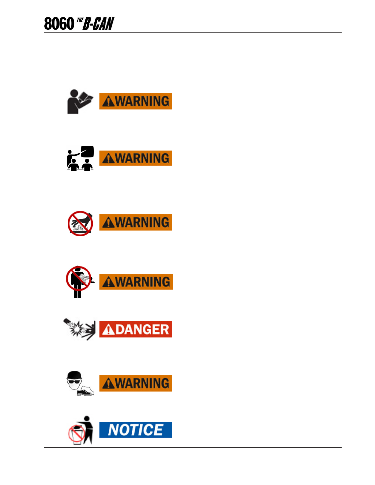
Sump Tank Assembly
The air oil mixture leaving the compressor assembly flows into the
sump tank assembly. The sump tank is the first stage of oil
separation in the 8060 UBI PTO compressor system. The sump
tank also acts as an oil reservoir to ensure there is plenty of oil
capacity to handle continuous air compressor operation.
The tank safety relief valve is located at the top of the sump tank.
This valve acts as a backup to protect the system from excessive
pressure buildup as a result of a system malfunction.
Also in the tank assembly is the oil fill cap and oil level sightglass.
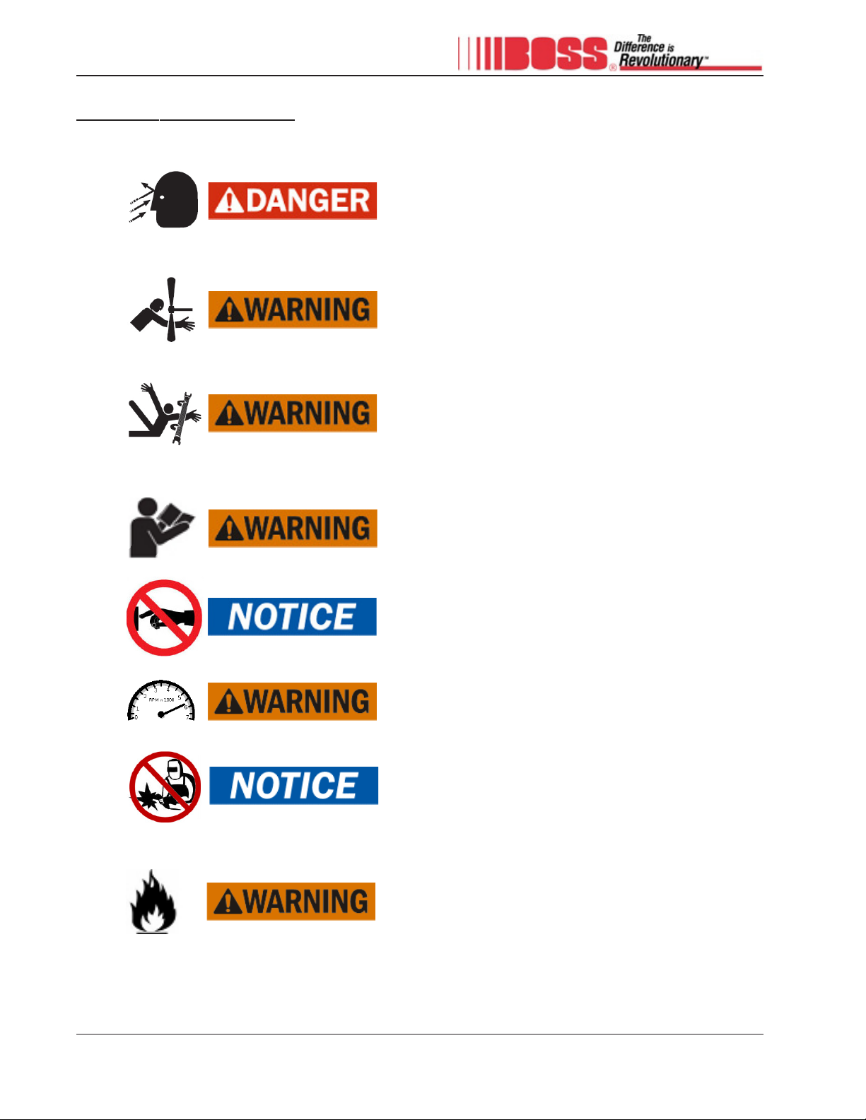
Compressor Assembly
The heart of the Boss 8060 UBI PTO air compressor system is the rotary
screw airend. The rotary screw is a positive displacement, oil flooded
device employing one stage of compression to achieve the desired
pressure. In operation, two helically grooved rotors mesh to compress air.
Intake air is trapped as the male lobes roll down the female grooves,
pushing trapped air along, compressing it until it reaches the discharge
port in the end of the stator. This delivers smooth-flowing, pulse-free air
to the sump tank.
The oil in a rotary screw airend serves three purposes:
• Lubricates the rotating parts and bearings.
• Serves as a cooling agent to remove the heat from compression.
• Seals the running clearances.
Mounted to the airend is a companion flange, intake valve, and mounting bracket.

17 309743
Description of Components
Subsystems (cont.)
The spin-on coalescer is the second and final stage of oil separation in the Boss 8060 UBI PTO
compressor system. As the oil laden air passes through the filter media, oil gathers on the walls and
collects at the bottom of the element. The oil that is separated is then returned to the rear of the
compressor assembly.
On the upstream side of the coalescer is the pressure transducer. This transducer provides precise
feedback to the B-CAN on the status of the compressor system.
On the downstream side of the coalescer is the regulator valve. The regulator valve is a proportional
control valve that sends a signal to close the intake valve when the system pressure has reached the
correct level.
Also mounted downstream of the coalescer is the blowdown valve. The blowdown valve’s function is
to relieve the system of air pressure when the 8060 UBI PTO compressor system is shut off. This
valve is piloted by a signal from the intake valve and vents the system pressure to atmosphere.
The most overlooked component in the Boss 8060 UBI PTO compressor system is the minimum
pressure orifice. This orifice is designed to maintain adequate pressure in the system to ensure proper
oil circulation.
Air Oil Manifold
The air oil manifold is a common point for senders and switches
along with filters and control valves. The air oil manifold is
divided into two sides: air and oil.
The air side contains the following:
• Spin-On Coalescer
• Pressure Transducer
• Regulator Valve
• Blowdown Valve
• Minimum Pressure Orifice
The oil side of the manifold contains the following:
• Spin-On Oil Filter
• Temperature Sender
• Thermal Valve
As oil is pushed out the bottom of the sump tank, it is directed to the spin-on oil filter. After the filter
is the thermal valve. The thermal valve bypasses the cooler at start-up to minimize the time to elevate
the system to proper operating temperature.
Lastly, on the oil side is the temperature sender. This sender provides feedback to the B-CAN on the
status of the compressor system.
18309743
1
1
2
2
3
3
4
4
A A
B B
C C
D D
Subsystems (cont.)
Description of Components
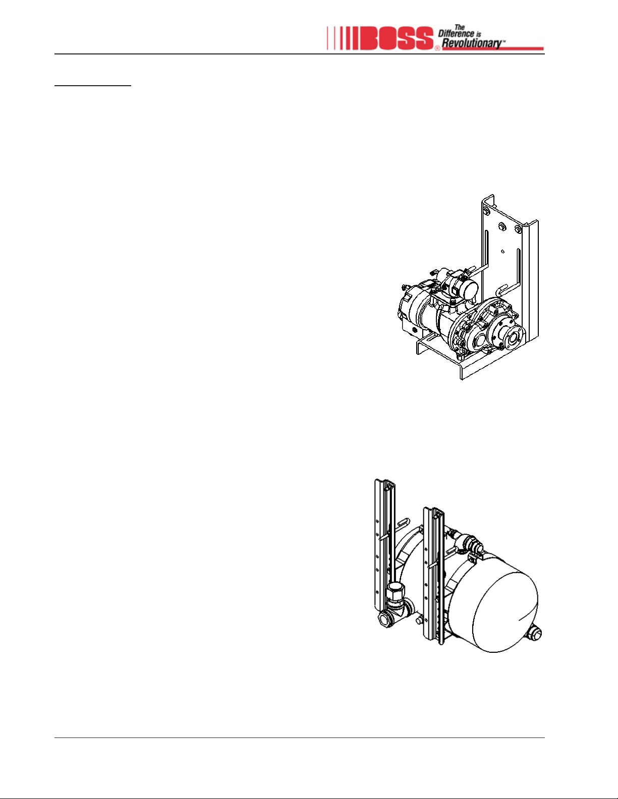
B-CAN Assembly and Harnesses
The B-CAN controller is the brain behind the Boss 8060 UBI PTO air
compressor system. The B-CAN is a compact, durable, and convenient
controller. It allows all system components, including a compressor,
generator, and hydraulic pump, to be controlled from one location with the
touch of a button. This controller receives feedback from the compressor
system to ensure proper performance. Utilizing the vehicle’s on-board
Controller Area Network (CAN), the B-CAN communicates with the vehicle
and PTO compressor systems. Along with the B-CAN controller are simple
plug and play harnesses to greatly reduce installation time.
Air Filter Assembly
The air filter assembly is the entrance for ambient air to the Boss 8060 UBI
PTO compressor system. Air is drawn through this assembly and into the
intake valve on the compressor assembly. The air filter assembly is a two
stage system that is capable of handling medium to high dust environ-
ments. The system incorporates an acoustical rain cap and corrosion
resistant housing. The air filter assembly also includes a service indicator
that shows the life of the filter even when the compressor system is off.
Cooler Assembly
The cooler assembly is an aerodynamically designed cooling package that
utilizes an electric fan that cycles on and off based on oil temperature to
ensure the temperature stays in the correct range.
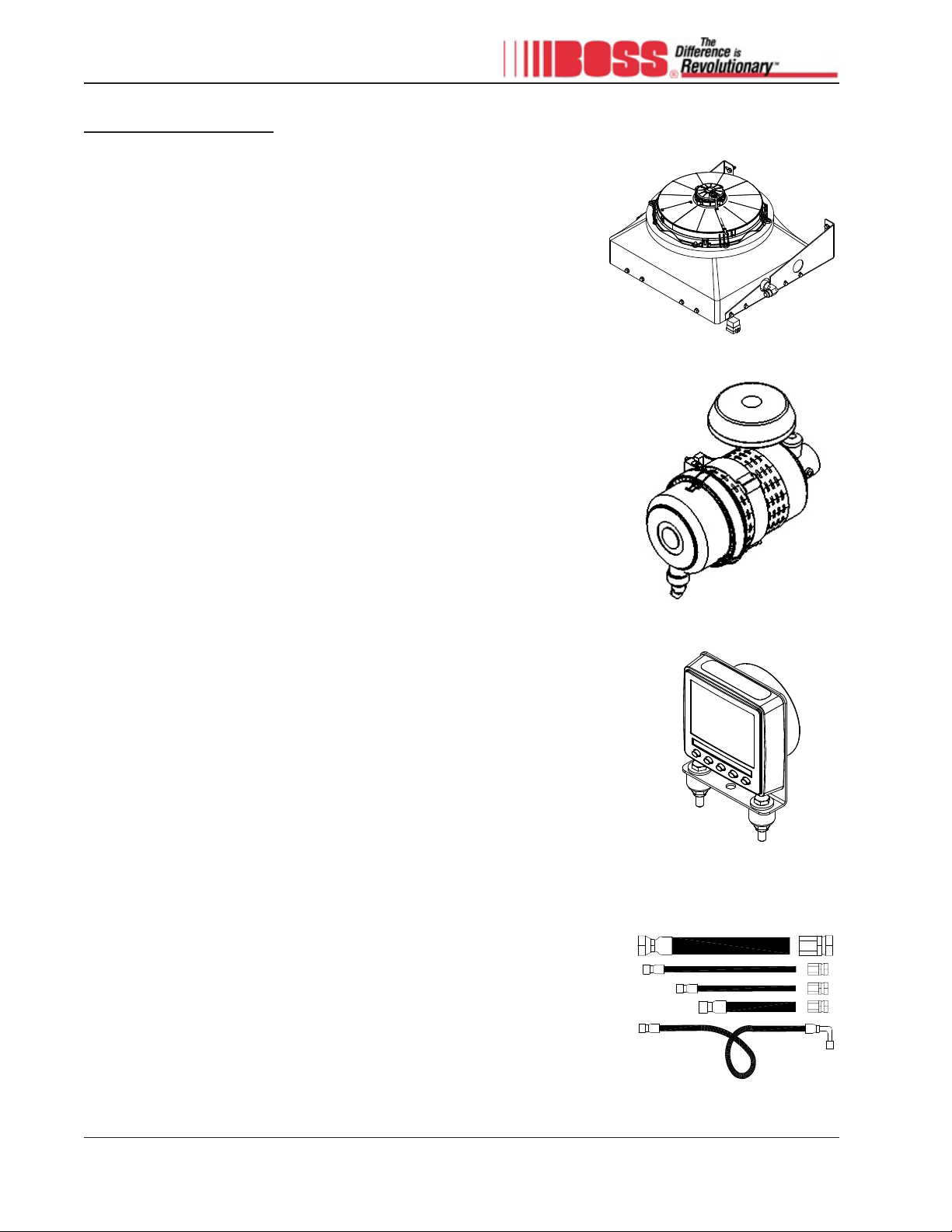
Hoses and Tubing
The 8060 UBI PTO compressor system is shipped with all the hoses and
tubing required for standard installations. The hoses and tubes are rated at
the pressures and temperatures required for safe operation. All hoses are
single wire braid hose with 37° JIC ends. The color and size differentiated
tubing uses push-on connections.

19 309743
Operation
Operation

20309743
Compressor General Overview
Operation
Inspection Prior to Moving Vehicle
At the start of your shift, before taking the vehicle to the job site in the morning, the following inspections should be
performed. This simple one-minute check will help to ensure you don’t drive to the job site with an inoperable compres-
sor.
1. With vehicle on a level surface check to ensure the oil level is at least halfway on the sightglass. If not, see
maintenance section for proper filling procedure.
Operation of the 8060 UBI PTO compressor system should only be performed by trained operators. Carefully read the
entire Operation section of this manual before attempting to operate the system. Be sure to follow all company policies
and procedures.
Operation of the compressor is controlled with the first button on the B-CAN. The color and text of the button changes
with the current state of operation. The possible states are:
If the system has a generator (GEN) or hydraulic pump (HYD)
installed, the 5th button will be used to control it. Engagement is the
same as for the compressor.
A green ENGAGE COMPR button indicates all safeties have been
met. Press this button to engage the compressor.
A yellow COMPR button indicates not all safeties have been met.
Press this button to display the reason(s) engagement cannot
occur.
A dark grey COMPR LOCKED button indicates the compressor is
locked and service is required. Press this button to display the
service that is needed.
A red STOP COMPR button indicates the compressor is currently
engaged. Press this button to disengage the compressor.
Table of contents
Other BOSSCO Air Compressor manuals

BOSSCO
BOSSCO Infinity User manual

BOSSCO
BOSSCO RCL-10 User manual

BOSSCO
BOSSCO BA435 PISTON Installation and user guide

BOSSCO
BOSSCO K36BP PISTON Installation and user guide

BOSSCO
BOSSCO 210 DUS JD4045 Installation and user guide

BOSSCO
BOSSCO BA440 PISTON User manual

BOSSCO
BOSSCO 36 BHP PISTON Installation and user guide
Popular Air Compressor manuals by other brands


TOOLCRAFT
TOOLCRAFT 2149347 operating instructions

Truper
Truper COMP-50LT manual

SHARKS
SHARKS Airstation SHK 476 Instruction for operation and maintenance

Challenge
Challenge T609 instruction manual

Craftsman
Craftsman 919.167620 owner's manual

Utile
Utile L240 Installation, operation & maintenance instructions


