BOSSCO RCL-10 User manual

UBOsSS
RCL-I0
COMPRESSOR
mui
Owner’s
Manua
OUBOSS
RCL-10
COMPRESSOR
LIMITER
INSTRUCTIONS
®
Please
read
the
instructions
carefully.
FEATURES
The
Dynamics
Processor
RCL-10
has
Compressor,
Limiter,
Expander,
and
more,
Noise
Gate
functions.
Adopting
a
high
quality
VCA,
the
RCL-10
allows
high
SN
ratio,
low
harmonic
distortion
and
little
tone
quality
deterioration.
Each
control
can
be
used
to
present
various
effects.
The
Key
In
Jack
allows
to
change
the
response
depending
on
the
type
of
input
signal,
and
the
Stereo
Link
Jack
allows
con-
nection
of
two
sets
of
RCL-10's
for
synchronization.
The
RCL-10
is
one
of
the
Micro
Studio
Series,
and
by
using
the
Rack
Mount
Adaptor
loptiona!),
any
two
of
the
Series
can
be
mounted
on
the
standard
19"
rack
(EIA-1U).
FUNCTIONS
The
RCL-10
has
four
functions;
Compressor,
Limiter,
Expander
and
Noise
Gate.
«Compressor/Limiter
Both
are
the
functions
of
compressing
the
input
signal,
but
different
in
the
threshold
level
(*1)
and
ratio
(*2)
settings.
Compressor
is
used
to
compress
the
signal
of
a
wide
dynamic
range
and
even
the
level.
Limiter
is
a
stronger
function
that
is
used
to
protect
a
unit
from
excessive
input
or
to
reduce
sound
distrotion.
«Expander
This
is
the
function
of
widening
the
dynamic
range
of
input
signal.
Use
this
to
make
a
dynamic
sound.
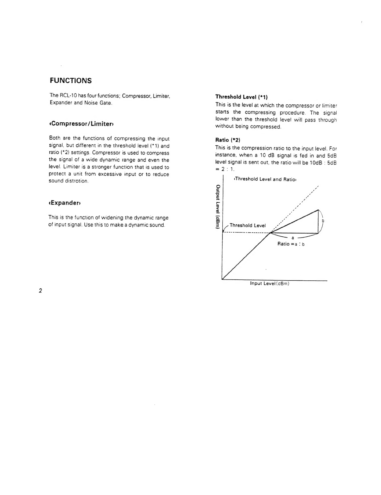
Threshold
Level
(*1)
This
is
the
level
at
which
the
compressor
or
limiter
Starts
the
compressing
procedure.
The
signal
lower
than
the
threshold
level
will
pass
through
without
being
compressed.
Ratio
(*2)
This
is
the
compression
ratio
to
the
input
level.
For
instance,
when
a
10
dB
signal
is
fed
in
and
5dB
level
signal
is
sent
out,
the
ratio
will
be
10dB
:
5dB
=2:1.
‘Threshold
Level
and
Ratio:
(wugp)
120a7
INdiInNO
Ratio
=a:
b
Input
Level
(aBm)

Attack
Time
This
is
the
time
needed
for
the
ratio
of
the
signal
over
the
threshold
level
to
reach
the
set
ratio.
Release
Time
This
is
the
time
required
for
the
signal
that
has
become
under
the
threshold
level
(=
the
signal
that
stops
compressing}
to
reach
the
normal
level.
‘Attack
Time
and
Release
Time
_----
Input
Level
(Ugp)
j8Adq
aS
A
a
ee
Threshold
Level
Output
Level
:
|
Attack
Time
|
|
x
|
Release
Time
Time
@
Control
Setting
Examples
[Trees]
tie
reer]
=a
‘Noise
Gater
Attack
Time
|
Release
Time
Fairly
Short)
Fairly
Short
This
serves
to
mute
the
signal
that
is
lower
than
the
set
level
(threshold
level).
Therefore,
it
can
be
effectively
used
for
removing
noise
when
nothing
is
being
played,
or
reducing
the
crosstalk
when
several
microphones
are
used.
Threshold
Level
The
signal
lower
than
this
level
will
be
muted.
Decay
Time
This
is
the
time
spent
for
the
muting.
Fairly
Short;
|
1
i
}
i

PANEL
DESCRIPTIONS
<FRONT
PANEL>
@
EFFECT
INDICATOR
This
lights
up
when
the
effect
is
turned
on.
So
you
can
easily
see
whether
the
unit
is
in
the
Normal
or
Effect
mode.
EFFECT
SWITCH
Each
time
this
switch
is
pushed,
the
unit
is
alternately
turned
to
the
Effect
and
Normal
modes.
OVERLOAD
INDICATOR
When
the
signal
fed
into
the
unit
is
too
high,
this
indicator
lights
up.
If
it
lights
up
too
often,
lower
the
input
level
of
the
connected
unit,
or
set
the
Level
Switch
@
to
the
“-10dBm”"
position.
GAIN
REDUCTION
INDICATOR
In
the
compressor
or
limiter
mode,
this
lights
up
when
the
unit
is
operating.
So,
this
can
be
an
aid
for
setting
the
threshold
level.
In
the
expander
mode,
this
lights
up
when
the
unit
is
not
operating,
and
goes
out
when
operating.
THRESHOLD
This
decides
the
threshold
level
(the
level
where
the
compressor
starts
working).
Rotating
it
clockwise
will
increase
the
level,
making
the
effect
of
the
compressor/limiter
weaker.
e
C8
°
*
In
Expander
mode
(when
the
ratio
is
1:
1.5
to
1:1),
this
knob
has
no
effect.
RATIO
This
adjusts
the
compression
ratio.
When
it
is
rotated
clockwise
from
the
center
position
(1:1
to
x:
1),
the
RCL-10
functions
as
compressor’
limiter.
And
when
rotated
counterclockwise
(1:1
to
1:
1.5),
it
functions
as an
expander.
At
its
Center
position,
the
compression
ratio
is
1:1,
therefore
none
of
the
compressor,
limiter
or
expander
works.
ATTACK
This
adjusts
the
attack
time.
Rotating
this
clock-
wise
will
make
the
attack
time
longer.
RELEASE
This
adjusts
the
release
time.
Rotating
it
clock-
wise
will
make
the
release
time
longer.
THRESHOLD
This
decides
the
threshold
level
of
the
noise
gate.
Rotating
the
knob
clockwise
will
increase
the
level.
At
its
fully
counterclockwise
position,
the
noise
gate
function
is
not
obtained
at
all.
DECAY
Dacay
Time
is
the
time
needed
for
the
input
signal
under
the
set
threshold
level
to
finally
fade
out.
Rotating
the
knob
clockwise
will
make
a
longer
decay
time.
OUTPUT
LEVEL
This
adjusts
the
output
level
of
the
effect
signal.
When
the
ratio
is
1:1,
setting
this
knob
to
the
center
position
will
make
the
output
and
input
levels
equal.
@
POWER
INDICATOR
This
lights
up
when
the
unit
is
turned
on.
@®
POWER
SWITCH
Push
this
switch
to
turn
the
unit
on,
and
push
it
again
to
turn
off.
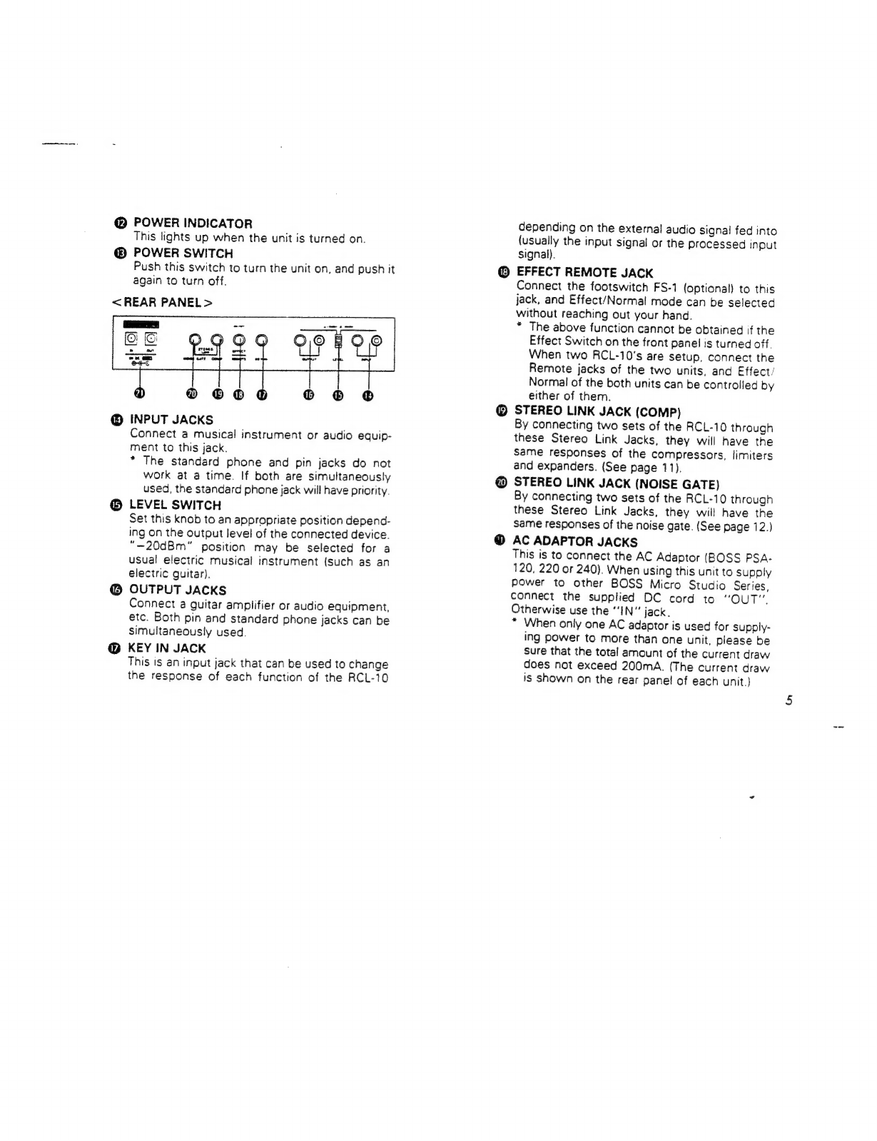
<REAR
PANEL>
@
INPUT
JACKS
Connect
a
musical
instrument
or
audio
equip-
ment
to
this
jack.
*
The
standard
phone
and
pin
jacks
do
not
work
at
a
time.
If
both
are
simultaneously
used,
the
standard
phone
jack
will
have
priority.
@
LEVEL
SWITCH
Set
this
knob
to
an
appropriate
position
depend-
ing
on
the
output
level
of
the
connected
device.
“—20dBm”
position
may
be
selected
for
a
usual
electric
musical
instrument
(such
as
an
electric
guitar).
@
OUTPUT
JACKS
Connect
a
guitar
amplifier
or
audio
equipment,
etc.
Both
pin
and
standard
phone
jacks
can
be
simultaneously
used.
@
KEY
IN
JACK
This
Is
an
input
jack
that
can
be
used
to
change
the
response
of
each
function
of
the
RCL-10
depending
on
the
externa!
audio
signal
fed
into
{usually
the
input
signal
or
the
processed
input
signal).
EFFECT
REMOTE
JACK
Connect
the
footswitch
FS-1
(optional)
to
this
jack,
and
Effect/Normal
mode
can
be
selected
without
reaching
out
your
hand.
*
The
above
function
cannot
be
obtained
if
the
Effect
Switch
on
the
front
panel
is
turned
off.
When
two
RCL-10's
are
setup,
connect
the
Remote
jacks
of
the
two
units,
and
Effect’
Normal
of
the
both
units
can
be
controlled
by
either
of
them.
STEREO
LINK
JACK
(COMP)
By
connecting
two
sets
of
the
RCL-10
through
these
Stereo
Link
Jacks,
they
will
have
the
Same
responses
of
the
compressors,
limiters
and
expanders.
(See
page
11),
STEREO
LINK
JACK
(NOISE
GATE)
By
connecting
two
sets
of
the
RCL-10
through
these
Stereo
Link
Jacks,
they
will
have
the
same
responses
of
the
noise
gate.
(See
page
12.)
AC
ADAPTOR
JACKS
This
is
to
connect
the
AC
Adaptor
(BOSS
PSA-
120,
220
or
240).
When
using
this
unit
to
supply
power
to
other
BOSS
Micro
Studio
Series,
connect
the
supplied
DC
cord
to
“OUT”.
Otherwise
use
the
“IN”
jack,
*
When
only
one
AC
adaptor
is
used
for
supply-
ing
power
to
more
than
one
unit,
please
be
sure
that
the
total
amount
of
the
current
draw
does
not
exceed
200mA.
(The
current
draw
is
Shown
on
the
rear
panel
of
each
unit.)
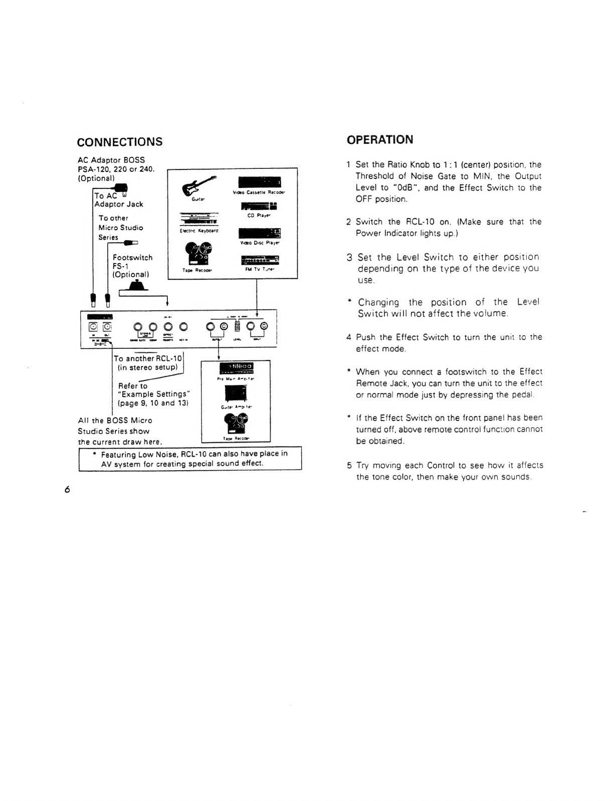
CONNECTIONS
AC
Adaptor
BOSS
PSA-120,
220
or
240.
(Optional)
Video
Cassette
Recoce’
Gutar
_
Lo
perme
He
ane
CO
Player
Elecine
Keyboard
tre
ee
|
To
AC
&
Adaptor
Jack
To
other
Micro
Studio
Series
Ves
Disc
Player
Footswitch
FS-1
(Optional)
To
another
RCL-10
(in
stereo
setup)
trod
Pre
Mar
dmc
ter
Gatar
Amo
he
|
Tape
Recade
“Example
Settings”
(page
9,
10
and
13)
All
the
BOSS
Micro
Studio
Series
show
the
current
draw
here.
*
Featuring
Low
Noise,
RCL-10
can
also
have
place
in
AV
system
for
creating
special
sound
effect.
OPERATION
*
Set
the
Ratio
Knob
to
1:1
(center)
position,
the
Threshold
of
Noise
Gate
to
MIN,
the
Output
Level
to
"0dB”,
and
the
Effect
Switch
to
the
OFF
position.
Switch
the
RCL-10
on.
(Make
sure
that
the
Power
Indicator
lights
up.)
Set
the
Level
Switch
to
either
position
depending
on
the
type
of
the
device
you
use.
Changing
the
position
of
the
Level
Switch
will
not
affect
the
volume.
Push
the
Effect
Switch
to
turn
the
unit
to
the
effect
mode.
When
you
connect
a
footswitch
to
the
Effect
Remote
Jack,
you
can
turn
the
unit
to
the
effect
or
normal
mode
just
by
depressing
the
pedal.
If
the
Effect
Switch
on
the
front
panel
has
been
turned
off,
above
remote
control
function
cannot
be
obtained.
Try
moving
each
Control
to
see
how
it
affects
the
tone
color,
then
make
your
own
sounds.
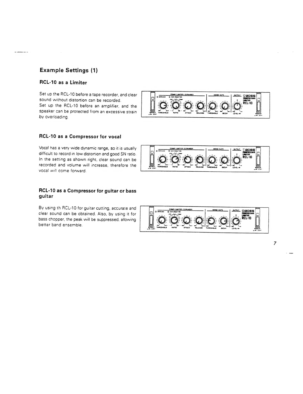
Example
Settings
(1)
RCL-10
as
a
Limiter
Set
up
the
RCL-10
before
a
tape
recorder,
and
clear
sound
without
distortion
can
be
recorded.
Set
up
the
RCL-10
before
an
amplifier,
and
the
speaker
can
be
protected
from
an
excessive
strain
by
overloading.
RCL-10
as
a
Compressor
for
vocal
Vocal
has
a
very
wide
dynamic
range,
so
it
is
usually
difficult
to
record
in
low
distortion
and
good
SN
ratio.
In
the
setting
as
shown
right,
clear
sound
can
be
recorded
and
volume
will
increase,
therefore
the
vocal
will
come
forward.
RCL-10
as
a
Compressor
for
guitar
or
bass
guitar
By
using
th
RCL-10
for
guitar
cutting,
accurate
and
clear
sound
can
be
obtained.
Also,
by
using
it
for
bass
chopper,
the
peak
will
be
suppressed,
allowing
better
band
ensemble.
aa.
1:6:
om
ea,
COMP
Lert
Eh
SE
PENDER
MOISE
Gate
ore
“BOSS
=:
attacx
RELEASE
Comes
uasiTER
/trpanoee
Corner
0
ommmcron
OHO!
OC
wtace
Nuease,
Tame
sHend
pecan
“Tree.
-

RCL-10
as
an
Expander
When
recording
drum
voices,
you
may
use
the
RCL-10
for
tom.
The
recorded
sound
will
be
extremely
dynamic.
RCL-10
as
a
Noise
Gate
In
a
setup
using
many
effect
units,
noise
will
increase
that
much.
Using
the
RCL-10
as
a
Noise
Gate
at
the
end
of
the
group
of
the
effect
units
will
remove
the
q
1
@)
undesired
noise
heard
when
nothing
is
being
played.
Ee
RCL-10
as
a
signal
gate
When
recording
drum
voices,
use
the
RCL-10
fora
en
bass
drum
and
cut
the
unnecessary
release
time,
and
the
recorded
sound
will
be
tight.
Also
by
using
it
,
{
LD
for
a
microphone,
the
crosstalk
among
the
micro-
EPPREL,
Tmarswoid
“nano
Warmer”
“Reueast
fo
phones
can
be
reduced,
and
clear
sound
will
be
obtained.

Example
Settings
(2)
The
RCL-10
features
a
Key
In
Jack
and
Stereo
Link
Jacks,
allowing
wide
variety
of
applications.
RCL-10
as
a
gate
echo
elas
ieaten
vimana
You
can
make
gate
echo
sound
which
is
often
used
pag
for
a
snare
drum.
Snare
Drum
Output
Output
Audio
Signal
Distributer
Reverb
Unit
Rhythm
Machine
(BOSS
J-5,
etc)
Output
(Roland
TR-909
TR-707
etc)
To
Key
In
Jack
To
Input
Jack
|
Output
To
Mixer,
etc
)

10
RCL-10
as
a
de-essor
for
vocal
To
make
clearer
vocal
sound,
you
may
boost
the
treble
by
using
equalizer.
This,
however,
inevitably
emphasizes
sibilant
sounds.
To
resolve
this
problem,
use
the
limiter
on
the
band
of
6kHz
which
contains
sibilant
sounds.
Input
Preamplifier,
Mixer
(BOSS
BX-400
etc)
Audio
Signal
Distributer
(BOSS
J-5
etc)
0
t
Graphic
Equalizer
utpu
(BOSS
Micro
Studio
Series
RGE-10)
Output
To
Key
In
Jack
To
Input
Jack
To
Mixer,
etc

RCL-10
as
a
Limiter
in
stereo
mae
ao
By
connecting
two
sets
of
the
RCL-10
through
the
ce
TE
ae
pe
|
cp.
|
ik.
Pe
Stereo
Link
Jacks
(COMP),
they
will
have
the
same
|
AD:
@
ND?
PAD:
MDA!
responses
of
the
Compressors,
Limiters
and
Tee
Seca
teens
ou
Expanders,
therefore,
even
in
stereo
use,
natural
limiting
effect
can
be
obtained.
ey
Near
od
AFFUCT
Tene
seco
2m
oo
*
Normally,
set
these
two
RCL-10’s
exactly
the
same.
If
they
are
set
differently,
the
one
with
smaller
amount
of
compression
will
synchronize
to
the
other
one.
Stereo
Outputs
Mi
O0e
Tape
Recorder
(Left
Channel)
To
Input
Jack
(Right
Channel)
To
Input
Jack
Output
Connect
two
Stereo
Link
Jacks
«COMP,
L
To
Tape
Recorder,
etc
1]

12
RCL-10
as
a
Noise
Gate
in
stereo
Lately,
more
stereo-out
effect
units
have
been
on
the
market,
so
you
may
sometimes
want
to
use
the
Noise
Gate
in
stereo.
If
so,
connect
two
sets
of
the
RCL-10's
through
the
Stereo
Links
(NOISE
GATE),
and
the
responses
of
these
two
units
will
be
the
same.
In
this
way,
noise
can
be
removed
without
spoiling
natural
impression.
*
Normally
set
these
two
RCL-10’s
exactly
the
same.
If
they
are
set
differently,
the
one
with
smaller
input
level
will
synchronize
to
the
other
one.
Electric
Guitar
{Left
Channel)
To
Input
Jack
Connect
two
Stereo
Link
Jacks
«NOISE
GATE)
Guitar
Amplifier
Guitar
Amplifier
(L)
(R)

RCL-10
as
an
Expander
for
distortion
sound
Example
Settings
Expressing
a
delicate
picking
nuance
in
guitar's
distortion
sound
is
not
an
easy
job.
Using
the
RCL-10
as
an
Expander,
however,
a
subtle
nuance
of
picking
=,
can
be
expressed,
reducing
noise
at
a
time.
Also,
by
setting
the
release
time
fairly
long,
you
can
control
the
level
of
the
distortion
sound
with
the
volume
control
of
the
guitar.
(BOSS
J-5, etc)
Input
|
Audio
Signal
Distributer
Output
Output
Electric
Guitar
To
Key
In
Jack
To
Input
Jack
Distortion
Unit
(BOSS
HM-2,
DS-1,
DF-2,
etc)
13

14
IMPORTANT
NOTES
@
Be
sure
to
use
the
AC
Adaptor
BOSS
PSA-120,
220
or
240
depending
on
the
line
voitage
system
in
your
country.
@
When
you
use
only
an
AC
adaptor
for
suppiying
power
to
more
than
one
unit,
please
be
sure
that
the
total
current
draw
does
not
exceed
200mA.
(The
current
draw
of
each
unit
is
shown
on
its
rear
panel.)
@®
When
the
unit
is
not
to
be
used
for
a
long
period
of
time,
disconnect
the
AC
adaptor
from
the
wail
socket.
@®
Avoid
using
the
unit
in
extreme
heat
or
humidity
or
where
it
may
be
affected
by
dust
@
Please
never
remove
the
cabinet
from
the
body
of
the
unit.
@
When
you
use
only
Micro
Studio
Series
without
optio-
nal
Rack
Mount
Adaptor
""RAD-10"’,
please
attatch
the
rubber
feet.
Refer
to
figure.
AC
ADAPTOR
BOSS
PSA-120,
220
OR
240
Be
sure
to
use
the
optional
BOSS
PSA
series.
Using
any
other
adaptor
will
cause
trouble.
RACK
MOUNT
INSTALLATION
The
RCL-10
is
one
of
the
BOSS
Micro
Studio
Series,
and
by
using
the
Rack
Mount
Adaptor
RAD-10,
any
two
sets
of
the
Series
can
be
mount-
ed
in
a
standard
19”
rack
(EIA-1U).
Remove
the
rubber
feet
(x4)
from.the
units,
then
attatch
the
units
to
the
Rack
Mount
Adaptor
RAD-10,
then
mount
the
whole
set
in
the
rack.

SPECIFICATIONS
Input
Level/Input
impedance:
-—20dBm/1MQ,
—10dBm’47kQ
Output
Level/Output
Impedance:
—20dBm/2kN,
—10dBm.2kN
Output
Load
Impedance:
over
10kN
+0
Frequency
Response:
10Hz
to
25kHz
(_
3B)
Residual
Noise:
under
95dBm
(INF-A,
Level
Switch
set
to
~20dBm)
Compressor/Limiter/Expander
@
Threshold:
-—40dBm
to
0dBm
(Level
Switch
set
to
-20dBm)
©
Ratio:
1:1.5to=x:1
@
Attack:
0.2ms
to
50ms
e
Release:
50ms
to
2s
Noise
Gate
@
Threshold:
-xto-10dBm
(Level
Switch
set
to
-20dBm)
@
Decay:
2ms
to
5s
Output
Gain:
-~=x
to+14dB
THD:
under
0.03%
Switches:
Power
Effect
Level
(—20dBm,
-10d8m)
Jacks:
Input
(Standard
Phone,
Pin)
Output
(Standard
Phone,
Pin)
Effect
Remote
(On/Off)
Key
In
Stereo
Link
«COMP»
Stereo
Link
«(NOISE
GATE)
AC
Adaptor
(In,
Out)
Indicators:
Power:
Current
Draw:
Dimensions:
Weight:
Accessory:
OPTIONS:
Power
Effect
Overload
Gain
Reduction
9V
DC
(BOSS
PSA-120,
220
or
240)
60mA
218(W)
x
44(H)
x
169(D)
mm
8-9/16"(W)
x
1-3/4"(H)
x
6-11/16''(D)
900¢/2
Ib
DC
Cord
(0.5m)
AC
Adaptor
BOSS
PSA-120,
220
or
240
Rack
Mount
Adaptor
RAD-10
Footswitch
FS-1
Micro
System
Rack
BMR-5
@
Specifications
are
subject
to
change
without
notice.
BOSS
Micro
Studio
Series
RCL-10
RBF-10
RGE-10
RPH-10
RDD-10
Compressor
‘Limiter
Flanger
Graphic
Equalizer
Phaser
Digital
Delay
15

Notes

UBOSS
Products
of
Roland
RCL-10
Instructions
Printed
in
Japan
’85
Sep.C.3
Jd
Ol-)
Other manuals for RCL-10
1
Table of contents
Other BOSSCO Air Compressor manuals

BOSSCO
BOSSCO BA435 PISTON Installation and user guide

BOSSCO
BOSSCO K36BP PISTON Installation and user guide

BOSSCO
BOSSCO BA440 PISTON User manual

BOSSCO
BOSSCO Infinity User manual

BOSSCO
BOSSCO 210 DUS JD4045 Installation and user guide

BOSSCO
BOSSCO 8060 UBI User manual

BOSSCO
BOSSCO 36 BHP PISTON Installation and user guide


