BOSSCO Ladderspan 3T User manual
Instruction Manual
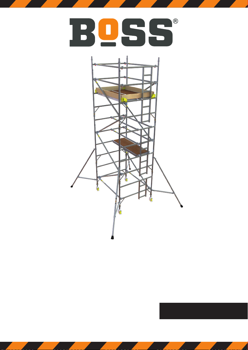
Ladderspan 3T
Mobile Aluminium Tower
1450/850 Ladderspan
3T - Through the Trapdoor Method
PN03299400_BoSS_Ladderspan 3T_IM_RevB 1121.indd 1PN03299400_BoSS_Ladderspan 3T_IM_RevB 1121.indd 1 04/11/2021 17:0704/11/2021 17:07

BoSS Ladderspan 3T Instruction Manual
PN03299400_BoSS_Ladderspan 3T_IM_RevB 1121.indd 2PN03299400_BoSS_Ladderspan 3T_IM_RevB 1121.indd 2 04/11/2021 17:0704/11/2021 17:07

1bossaccesstowers.com
Contents
1Safety First
1.1 Introduction 2
1.2 Tower Designation 3
1.3 Maintenance - storage - transport 3
2Building the Tower
2.1 Pre-Assembly Checks 4
2.2 Component Diagram 5
2.3 Quantity Schedule 6
2.4 Stabilisers 9
2.5 Assembly 10
2.5.1 Assembly for 1450 Towers 11
2.5.2 Assembly for 850 Towers 16
2.6 Dismantling 18
3 Using the Tower
3.1 Safety Checklist 19
3.2 Pre-Use Checklist 19
3.3 Use 20
3.4 Movement of the assembled prefabricated tower scaffold 21
PN03299400_BoSS_Ladderspan 3T_IM_RevB 1121.indd 1PN03299400_BoSS_Ladderspan 3T_IM_RevB 1121.indd 1 04/11/2021 17:0704/11/2021 17:07

2BoSS Ladderspan 3T Instruction Manual
1 Safety First
1.1 Introduction
Please read this instruction manual carefully.
THIS INSTRUCTION MANUAL SHALL BE AVAILABLE AT THE LOCATION OF USE
OF THIS MOBILE ACCESS TOWER.
THIS PRODUCT SHALL ONLY BE USED IN ACCORDANCE WITH THIS MANUAL.
FAILURE TO FOLLOW THESE INSTRUCTIONS MAY LEAD TO
DEATH OR SERIOUS INJURY.
IF ANY ASPECT OF THESE INSTRUCTIONS CONFLICTS WITH LOCAL
REGULATIONS PLEASE CONTACT WERNER UK SALES & DISTRIBUTION LTD.
FOR ADVICE.
Please note that diagrams are for illustrative purposes only.
Instruction manuals are also available to download at www.bossaccesstowers.com.
BoSS mobile aluminium towers are light-weight scaffold towers used throughout
the building and construction industry for both indoor and outdoor access solutions
where a stable and secure platform is required. Ideal for maintenance and
installation work or short-term access, the highly versatile towers provide a strong
working platform for a variety of heights.
Verification and assessment documentation is held by Werner UK Sales &
Distribution Ltd.
If you need further information, design advice, additional instruction manuals or any
other help with this product, please contact Werner UK Sales & Distribution Ltd.
Compliances
The BoSS Ladderspan mobile tower system has been
designed, tested, approved and certified to EN 1004-1:2020.
This instruction manual is in compliance with EN1298-IM-en.
PN03299400_BoSS_Ladderspan 3T_IM_RevB 1121.indd 2PN03299400_BoSS_Ladderspan 3T_IM_RevB 1121.indd 2 04/11/2021 17:0704/11/2021 17:07

3bossaccesstowers.com
1 Safety First
1.2 Tower Designation
EN 1004 3 8/12 XXXD H2
Design Code
Load Class (2 = 153kg/m2UDL, 3 = 204kg/m2UDL)
Max. Platform Height Outdoors (m)
Max. Platform Height Indoors (m)
Access Method
A = Stairway, B = Stair ladder, C = Inclined Ladder, D = Vertical Ladder
Clear Height Class (H1 = 1.85m, H2 = 1.90m)
1.3 Maintenance - storage – transport
•The BoSS mobile tower system is robust and requires little maintenance.
•All components and their parts should be regularly inspected to identify
damage, particularly to joints.
•Refer to the BoSS Inspection Guidance for detailed inspection and
maintenance advice, the guidance is available to download at:
www.bossaccesstowers.com.
•Threads, hinges, and brace latches may be lubricated with light oil. Ensure oil
does not contaminate climbing or walking surfaces.
•Safety labels should be kept legible. Replacement labels are available from
Werner UK Sales & Distribution Ltd.
•Surfaces should be kept reasonably free of dried paint, plaster etc.
•Use of solvents on wooden platform surfaces and plastic components should
be avoided.
•Components should be stored in clean, dry conditions with due care to prevent
damage.
•During transportation ensure components are not damaged by excessive
strapping forces.
PN03299400_BoSS_Ladderspan 3T_IM_RevB 1121.indd 3PN03299400_BoSS_Ladderspan 3T_IM_RevB 1121.indd 3 04/11/2021 17:0704/11/2021 17:07
Other manuals for Ladderspan 3T
2
This manual suits for next models
3
Table of contents


