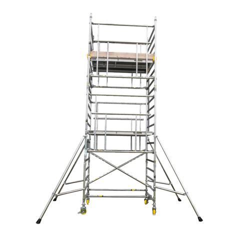
BOSSCO Ladderspan 3T User manual

Instruction Manual
Ladderspan 3T
Mobile Aluminium Tower
1450/850 Ladderspan
3T - Through the Trapdoor Method
EN 1004-2 en

BoSS Ladderspan 3T Instruction Manual

1bossaccesstowers.com
Contents
1Safety First
1.1 Introduction 2
1.2 Tower Designation 3
1.3 Maintenance - Storage - Transport 3
2Building the Tower
2.1 Pre-Assembly Checks 4
2.2 Component Diagram 6
2.3 Quantity Schedule 8
2.4 Stabilisers 11
2.5 Assembly 12
2.5.1 Assembly General: Steps to 14
2.5.2 Assembly For 1450 Towers: Steps to 15
2.5.3 Assembly For 850 Towers: Steps to 18
2.6 Dismantling 20
3 Using the Tower
3.1 Safety Checklist 21
3.2 Pre-Use Checklist 21
3.3 Use 22
3.4 Movement Of TheAssembled Prefabricated Tower Scaffold 24
1 3
4 8
4 9

2BoSS Ladderspan 3T Instruction Manual
1 Safety First
1.1 Introduction
Please read this instruction manual carefully.
This instruction manual shall be available at the location of use of
this mobile access tower. Instruction manuals are also available to
download at www.bossaccesstowers.com.
This product shall only be used in accordance with this manual without any
modification.
FAILURE TO FOLLOW THESE INSTRUCTIONS MAY LEAD TO
DEATH OR SERIOUS INJURY.
Mobile access towers must always be used in accordance with the national
regulations. If any aspect of these instructions conflicts with local regulations please
contact Werner UK Sales & Distribution Ltd. for advice.
Please note that diagrams are for illustrative purposes only.
User training courses are available, but must not be used as a substitute for
familiarity with this manual.
BoSS mobile aluminium towers are light-weight scaffold towers used throughout
the building and construction industry for both indoor and outdoor access solutions
where a stable and secure platform is required. Ideal for maintenance and
installation work or short-term access, the highly versatile towers provide a strong
working platform for a variety of heights.
Verification and assessment documentation is held by Werner UK Sales &
Distribution Ltd.
Compliances The BoSS Ladderspan mobile tower system has been
designed, tested, approved and certified to EN 1004-1:2020.
This instruction manual is in compliance with EN 1004-2-en.

3bossaccesstowers.com
1 Safety First
1.2 Tower Designation
EN 1004 3 8/12 XXXD H2
Design Code
Load Class (2 = 153kg/m2UDL, 3 = 204kg/m2UDL*)
Max. Platform Height Outdoors (m)
Max. Platform Height Indoors (m)
Access Method
A = Stairway, B = Stair ladder, C = Inclined Ladder, D = Vertical Ladder
Clear Height Class (H1 = 1.85m, H2 = 1.90m)
*UDL = Uniformly distributed load
1.3 Maintenance - Storage – Transport
•The BoSS mobile tower system is robust and requires little maintenance.
•All components and their parts should be regularly inspected to identify
damage, particularly to joints.
•Refer to the BoSS Inspection Guidance for detailed inspection and
maintenance advice, the guidance is available to download at:
www.bossaccesstowers.com.
•Threads, hinges, and brace latches may be lubricated with light oil. Ensure oil
does not contaminate climbing or walking surfaces.
•Safety labels should be kept legible. Replacement labels are available from
Werner UK Sales & Distribution Ltd.
•Surfaces should be kept reasonably free of dried paint, plaster etc.
•Use of solvents on wooden platform surfaces and plastic components should
be avoided.
•Components should be stored in clean, dry conditions with due care to prevent
damage.
•During transportation ensure components are not damaged by excessive
strapping forces.

4BoSS Ladderspan 3T Instruction Manual
2 Building The Tower
2.1 Pre-Assembly Checks
•Check overhead that the area into which the structure is to be erected contains
no obstructions, particularly electrical or radio radiation hazards. The structure is
conductive.
•Ensure the ground on which the mobile access tower is to be erected is capable
of supporting the tower in use.
•Check the surface is level within the 210mm range of the adjustable legs.
•Only components specified in this manual shall be used with BoSS towers.
Check all required components are onsite and in a suitable working condition.
•Damaged components shall not be used and must
be put beyond use and disposed of according to local
regulations.
•Adjustable legs should only be used for levelling purposes and never to gain
extra height.
•Ensure distance from the ground to first climbing rung is less than 400mm.
•Only climb the tower from the inside using the access
method provided.
•This tower provides a work platform. It must not be
used to access other structures.
•Tower scaffolds are not designed to be lifted or suspended.
•Ensure the safe working load on the structure is not exceeded.
•Tools and materials should be lifted using a reliable lifting material (e.g. a strong
rope) employing a reliable knot (e.g. clove hitch) to ensure safe fastening and
always lift within the footprint of the prefabricated tower scaffold (i.e. within the
area bounded by the stabilisers).

5bossaccesstowers.com
•Check this manual is available and its contents familiar to all those involved.
•If assembling outdoors; check the forecast windspeed.
| The assembled tower is certified to wind forces
equating to 27mph, but handling components under
those conditions would be hazardous.
| Also consider the wind funnelling effect of nearby
buildings.
•Towers greater than 8.2m platform height are for indoor use only.
•This structure is designed to be self-supporting under the loading condition
requirements of EN 1004-1:2020 and does not require tying in. Consideration
should be given to potential wind conditions if the tower is left unattended.
2 Building The Tower

6BoSS Ladderspan 3T Instruction Manual
2.2 Component Diagram
2 Building The Tower
Instruction
Manual
Horizontal
Brace
Span
Frame
4 Rung
Platform
(Fixed and
Trapdoor
Platforms)
Ladder Frame
4 Rung
End Toe
Board
Stabiliser
Span
Frame
2 Rung
Ladder Frame
2 Rung
Adjustable Leg
Castor
Diagonal
Brace
Side
Toe
Board

7bossaccesstowers.com
Component Weights
2 Building The Tower
Component
Code Name Weight (kgs)
32842300 Castor 150mm 3.3
33551300 Adjustable Leg 1.1
60851300 Ladder Frame 850 2 Rung 4.7
60251300 Span Frame 850 2 Rung 2.7
60751300 Ladder Frame 850 3 Rung 6.7
60151300 Span Frame 850 3 Rung 3.4
60651300 Ladder Frame 850 4 Rung 8.7
60051300 Span Frame 850 4 Rung 4.1
61151300 Ladder Frame 1450 2 Rung 5.4
60551300 Span Frame 1450 2 Rung 4.0
61051300 Ladder Frame 1450 3 Rung 8.0
60451300 Span Frame 1450 3 Rung 5.6
60951300 Ladder Frame 1450 4 Rung 10.4
60351300 Span Frame 1450 4 Rung 7.1
30151100 Fixed Platform 1.8m 11.8
30251100 Fixed Platform 2.5m 16.0
30451100 Trapdoor Platform 1.8m 12.7
30551100 Trapdoor Platform 2.5m 16.3
31251300 Horizontal Brace 1.8m (red) 2.0
34851300 Horizontal Brace 2.5m (red) 2.4
31351300 Diagonal Brace 2.1m (blue) 2.1
31451300 Diagonal Brace 2.7m (blue) 2.5
30450900 Side Toe Board 1.8m 3.2
30550900 Side Toe Board 2.5m 4.4
30250900 End Toe Board 0.85m 1.0
30350900 End Toe Board 1.45m 2.1
30150900 Toe Board Holder 0.3
31751300 SP7 Fixed Stabiliser 3.8
31851300 SP10 Telescopic Stabiliser 8.8
31951300 SP15 Telescopic Stabiliser 12.8

8BoSS Ladderspan 3T Instruction Manual
2.3 Quantity Schedule
BoSS 1450 Ladderspan to EN 1004: Available in 2 lengths - 1.8m and 2.5m
Internal or External Use Internal Use
Component Working
Height (m) 3.2 3.7 4.2 4.7 5.2 5.7 6.2 6.7 7.2 7.7 8.2 8.7 9.2 9.7 10.2 10.7 11.2 11.7 12.2 12.7 13.2 13.7 14.2
Code Name Platform
Height (m) 1.2 1.7 2.2 2.7 3.2 3.7 4.2 4.7 5.2 5.7 6.2 6.7 7.2 7.7 8.2 8.7 9.2 9.7 10.2 10.7 11.2 11.7 12.2
32842300 Castor 150mm 4 4 4 4 4 4 4 4 4 4 4 4 4 4 4 4 4 4 4 4 4 4 4
33551300 Adjustable Leg 4 4 4 4 4 4 4 4 4 4 4 4 4 4 4 4 4 4 4 4 4 4 4
61151300 Ladder Frame 1450 2 Rung - 1 1 - - 1 1 - - 1 1 - - 1 1 - - 1 1 - - 1 1
60551300 Span Frame 1450 2 Rung - 1 1 - - 1 1 - - 1 1 - - 1 1 - - 1 1 - - 1 1
61051300 Ladder Frame 1450 3 Rung - 1 - 1 - 1 - 1 - 1 - 1 - 1 - 1 - 1 - 1 - 1 -
60451300 Span Frame 1450 3 Rung - 1 - 1 - 1 - 1 - 1 - 1 - 1 - 1 - 1 - 1 - 1 -
60951300 Ladder Frame 1450 4 Rung 1 - 1 1 2 1 2 2 3 2 3 3 4 3 4 4 5 4 5 5 6 5 6
60351300 Span Frame 1450 4 Rung 1 - 1 1 2 1 2 2 3 2 3 3 4 3 4 4 5 4 5 5 6 5 6
30151100/
30251100
Fixed Platform 1.8m
and 2.5m 1 1 1 2 1 1 1 2 1 1 1 2 1 1 1 2 1 1 1 2 1 1 1
30451100/
30551100
Trapdoor Platform 1.8m and
2.5m 1 1 1 1 2 2 2 2 3 3 3 3 4 4 4 4 5 5 5 5 6 6 6
31251300/
34851300
Horizontal Brace 1.8m
and 2.5m (red) 6 6 6 10 10 10 10 14 14 14 14 18 18 18 18 22 22 22 22 26 26 26 26
31351300/
31451300
Diagonal Brace 2.1m
and 2.7m (blue) 2 4 4 6 6 8 8 10 10 12 12 14 14 16 16 18 18 20 20 22 22 24 24
30450900/
30550900
Side Toe Board 1.8m
and 2.5m 2 2 2 2 2 2 2 2 2 2 2 2 2 2 2 2 2 2 2 2 2 2 2
30350900 End Toe Board 1.45m 2 2 2 2 2 2 2 2 2 2 2 2 2 2 2 2 2 2 2 2 2 2 2
30150900 Toe Board Holder 4 4 4 4 4 4 4 4 4 4 4 4 4 4 4 4 4 4 4 4 4 4 4
31751300 SP7 Fixed Stabiliser 4 4 4 4 4 4 4 - - - - - - - - - - - - - - - -
31851300 SP10 Telescopic Stabiliser - - - - - - - 4 4 4 4 4 4 - - 4 4 4 4 4 4 4 4
31951300 SP15 Telescopic Stabiliser - - - - - - - - - - - - - 4 4 - - - - - - - -
Tower Total Self-weight 1.8m (kgs) 103 113 116 145 149 159 163 211 216 226 230 258 263 288 292 304 309 319 323 351 356 366 369
Tower Total Self-weight 2.5m (kgs) 116 127 131 165 170 180 184 239 243 254 257 292 296 323 327 346 350 360 364 399 403 414 418
Max. Exerted Leg Load 1.8m (kgs) 150 150 150 150 160 170 180 190 200 210 220 240 255 270 300 300 300 310 310 310 320 320 320
Max. Exerted Leg Load 2.5m (kgs) 160 160 170 170 180 180 190 190 200 200 210 260 305 310 320 330 340 350 360 370 380 390 400
2 Building The Tower

9bossaccesstowers.com
BoSS 850 Ladderspan to EN 1004: Available in 2 lengths - 1.8m and 2.5m
Internal or External Use Internal Use
Component Working
Height (m) 3.2 3.7 4.2 4.7 5.2 5.7 6.2 6.7 7.2 7.7 8.2 8.7 9.2 9.7 10.2 10.7 11.2 11.7 12.2 12.7 13.2 13.7 14.2
Code Name Platform
Height (m) 1.2 1.7 2.2 2.7 3.2 3.7 4.2 4.7 5.2 5.7 6.2 6.7 7.2 7.7 8.2 8.7 9.2 9.7 10.2 10.7 11.2 11.7 12.2
32842300 Castor 150mm 4 4 4 4 4 4 4 4 4 4 4 4 4 4 4 4 4 4 4 4 4 4 4
33551300 Adjustable Leg 4 4 4 4 4 4 4 4 4 4 4 4 4 4 4 4 4 4 4 4 4 4 4
60851300 Ladder Frame 850 2 Rung - 1 1 - - 1 1 - - 1 1 - - 1 1 - - 1 1 - - 1 1
60251300 Span Frame 850 2 Rung - 1 1 - - 1 1 - - 1 1 - - 1 1 - - 1 1 - - 1 1
60751300 Ladder Frame 850 3 Rung - 1 - 1 - 1 - 1 - 1 - 1 - 1 - 1 - 1 - 1 - 1 -
60151300 Span Frame 850 3 Rung - 1 - 1 - 1 - 1 - 1 - 1 - 1 - 1 - 1 - 1 - 1 -
60651300 Ladder Frame 850 4 Rung 1 - 1 1 2 1 2 2 3 2 3 3 4 3 4 4 5 4 5 5 6 5 6
60051300 Span Frame 850 4 Rung 1 - 1 1 2 1 2 2 3 2 3 3 4 3 4 4 5 4 5 5 6 5 6
30151100/
30251100
Fixed Platform 1.8m
and 2.5m - - - 1 - - - 1 - - - 1 - - - 1 - - - 1 - - -
30451100/
30551100
Trapdoor Platform 1.8m and
2.5m 1 1 1 1 2 2 2 2 3 3 3 3 4 4 4 4 5 5 5 5 6 6 6
31251300/
34851300
Horizontal Brace 1.8m
and 2.5m (red) 6 6 6 10 10 10 10 14 14 14 14 18 18 18 18 22 22 22 22 26 26 26 26
31351300/
31451300
Diagonal Brace 2.1m
and 2.7m (blue) 2 4 4 6 6 8 8 10 10 12 12 14 14 16 16 18 18 20 20 22 22 24 24
30450900/
30550900
Side Toe Board 1.8m
and 2.5m 2 2 2 2 2 2 2 2 2 2 2 2 2 2 2 2 2 2 2 2 2 2 2
30250900 End Toe Board 0.85m 2 2 2 2 2 2 2 2 2 2 2 2 2 2 2 2 2 2 2 2 2 2 2
30150900 Toe Board Holder 4 4 4 4 4 4 4 4 4 4 4 4 4 4 4 4 4 4 4 4 4 4 4
31751300 SP7 Fixed Stabiliser 4 4 4 4 4 4 4 - - - - - - - - - - - - - - - -
31851300 SP10 Telescopic Stabiliser - - - - - - - 4 4 4 4 4 4 - - 4 4 4 4 4 4 4 4
31951300 SP15 Telescopic Stabiliser - - - - - - - - - - - - - 4 4 - - - - - - - -
Tower Total Self-weight 1.8m (kgs) 84 93 96 122 126 135 138 184 188 197 200 226 230 255 257 284 288 297 299 310 314 323 325
Tower Total Self-weight 2.5m (kgs) 93 103 106 139 142 152 154 208 211 220 223 256 259 285 288 305 308 318 321 354 357 367 369
Max. Exerted Leg Load 1.8m (kgs) 150 150 155 155 155 155 155 160 160 160 160 160 185 210 235 260 285 310 325 330 335 340 345
Max. Exerted Leg Load 2.5m (kgs) 140 140 140 140 150 150 150 150 160 160 170 170 175 200 230 230 240 250 260 270 280 285 285
2 Building The Tower

10 BoSS Ladderspan 3T Instruction Manual
Assembly Variations
This section lists the permitted component variation from the Quantity Schedule.
Note: These substitutions must be made before assembly.
Stabilisers
Stabilisers with Universal
Clamps may be substituted:
Castors
Other Castor sizes and types
may be substituted:
High Clearance Frame If side walk-through access is required at the base
of 4.2m, 6.2m, 8.2m, 10.2m or 12.2m platform
height towers, high clearance frames may be used
in place of the four lower diagonal braces and two
lower horizontal braces.
High clearance frames must not be used in
conjunction with walk-through frames.
Component
Code Description Weight
(kg)
30051500 High Clearance Frame
1.8m 10.0
30151500 High Clearance Frame
2.5m 12.0
2 Building The Tower
Component
Code Description Weight
(kg)
31842300 Diameter 150mm (Tyred) 3.2
32942300 Diameter 200mm 3.9
31942300 Diameter 200mm (Tyred) 3.9
Component
Code Description Weight
(kg)
31751400 SP7 4.0
31851400 SP10 9.0
31951400 SP15 13.1

11bossaccesstowers.com
Walk-through Frame
If side walk-through access is required at the base of
4.2m, 6.2m, 8.2m, 10.2m or 12.2m platform height
towers, high clearance frames may be used in place
of the four lower diagonal braces and two lower
horizontal braces.
High clearance frames must not be used in
conjunction with walk-through frames.
If end walk-through access is required at the base
of 2.2m, 4.2m, 6.2m, 8.2m, 10.2m or 12.2m platform
height, 1450 wide towers, walk-through frames may
be used.
In this case the 1m ladder frame and span frame
must be tted above the walk-through frames.
Walk-through frames must not be used in addition to
high clearance frames.
Component
Code Description Weight(kg)
33151700 Walk-through Frame
2.0m 10.8
2 Building The Tower
2.4 Stabilisers
X
Y
90%
Double Width 1450
Tower Single Width 850 Tower
1.8m 2.5m 1.8m 2.5m
X & Y X & Y X & Y X Y
SP7 3351 3629 2294 3201 3201
SP10 4789 5100 4458 4734 3734
SP15 5520 5838 5195 5485 6074
SP10 and SP15 stabilisers must always be fully extended.
Position the lower clamp so that the arm is as close to horizontal as possible. Adjust
the position of the top clamp to ensure the stabiliser foot is in firm contact with the
ground. Ensure the clamps are secure.

12 BoSS Ladderspan 3T Instruction Manual
2 Building The Tower
2.5 Assembly
This tower structure must be assembled, and components oriented, in accordance
with this instruction manual. Deviation from this instruction manual is not permitted.
•No tools are required for assembly.
•The assembly uses the 3T (Through the Trapdoor) method that provides
collective fall protection.
•The tower may be assembled by a single person, but it is recommended that
two or more are used to pass up components on the taller assemblies.
•Components must be lifted within the footprint of the tower using a reliable
method such as a strong rope with a clove hitch knot.
•Castor brakes should be locked as soon as the tower base is in position.
•The tower base should be levelled to within 0.6° before continuing the assembly.
•The adjustable legs are for levelling the tower only and not to be used to gain
extra height.
•Ensure when the base is levelled the distance from the ground to the rst
climbing rung is less than 400mm.
•Stabilisers of the size specied in the quantity schedule should be tted at the
earliest opportunity.

13bossaccesstowers.com
2 Building The Tower
•Always start assembly with the smallest end frames at the base.
Platform Height (m) Frame at Base
1.7, 2.2, 3.7, 4.2, 5.7, 6.2, 7.7, 9.7, 10.2, 11.7,12.2 2 Rung
2.7, 4.7, 6.7, 8.7, 10.7 3 Rung
1.2, 3.2, 5.2, 7.2, 9.2, 11.2 4 Rung
•Where all three frames are specied, start with the 2 rung, 3 rung next and
4 rung on top. Refer to the quantity schedule for details.
Platform heights:
1.2m, 3.2m, 5.2m, 7.2m, 9.2m, 11.2m Platform heights:
2.2m, 4.2m, 6.2m, 8.2m, 10.2m, 12.2m
Platform heights:
1.7m, 3.7m, 5.7m, 9.7m, 11.7m Platform heights:
2.7m, 4.7m, 6.7m, 8.7m, 10.7m, 12.7m

14 BoSS Ladderspan 3T Instruction Manual
2.5.1 Assembly General
Push castor into adjustable
leg. Push castor/adjustable leg
assemblies into a span frame. Lock
castors. Repeat procedure with a ladder
frame.
It is recommended that for ease of
levelling a gap of 50mm is left between
the bottom of the leg and the adjustable
nut.
Fit one horizontal brace (red) onto
the vertical of a span frame, just
above the bottom rung, with the claw
facing outwards. The frame will now be
self-supporting.
All locking claws must be opened
before tting.
Position the ladder frame as
shown and fit the other end of the
horizontal brace on to the vertical (just
above the bottom rung).
Fit a second horizontal brace between
the bottom rungs on the other side of the
frames to square the tower.
1
2 Building The Tower
2
Unlocked
Locked
Locked
Assembly for 1450 towers, see page 15 for following steps.
Assembly for 850 towers, see page 18 for following steps.
3

15bossaccesstowers.com
2 Building The Tower
2.5.2 Assembly For 1450 Towers
The procedure illustrated shows a 4.2m platform height tower starting with a 2 rung
end frame.
Fit two additional end frames,
ensuring the frame interlock
clips are engaged.
Fit two diagonal braces (blue) in
opposite directions between the 1st
and 3rd rungs.
Ensure the frames are vertical and
level by checking with a spirit level and
setting the adjustable legs as required.
Only use the adjustment on the legs
to level the tower and not to gain
extra height.
Fit the next pair of diagonal braces
in opposite directions between the
3rd and 5th rungs. Fit a trapdoor platform
on the 4th rung (2.0m) with the trapdoor
next to the ladder. Ensure the trapdoor
is positioned with the hinges towards the
outside of the tower as shown.
Climb the ladder from the protected
trapdoor position, fit the horizontal
braces on the 5th and 6th rungs (in that
order) on both sides of the platform.
When horizontal braces are fitted as
guardrails, they should be 0.5m and
1.0m (1 and 2 rungs) above the platform
level in all cases.
Do not climb onto the platform until
all guardrails are in place.
4
INTERLOCK CLIP
Locked
Unlocked
5

16 BoSS Ladderspan 3T Instruction Manual
2 Building The Tower
Fit stabilisers (see notes
on page 11).
Continue the procedure until the
required height is reached, adding
additional pairs of end frames, diagonal
braces and fitting trapdoor platforms,
as shown on previous steps. At every
platform level, add horizontal braces as
guardrails from the protected position
within the trapdoor (as shown in Step 5).
At the required platform height, fit the
fixed platform and a trapdoor platform
alongside it. Fit the final guardrails (as
shown in Step 5).
6
7

18 BoSS Ladderspan 3T Instruction Manual
2 Building the Tower
2.5.3 Assembly For 850 Towers
The procedure illustrated shows a 3.2m platform height tower starting with a 4 rung
end frame.
Fit a trapdoor platform on the 2nd
rung. Fit the horizontal braces on
both sides of the tower. When horizontal
braces are fitted as guardrails, they
should be 0.5m and 1.0m (1 and 2
rungs) above the platform level in all
case.
Fit two diagonal braces in
opposite directions between the
1st and 3rd rungs.
Ensure that the frames are vertical
and level by checking with a spirit level
and setting the adjustable legs as
necessary.
Only use the adjustment on the legs
to level the tower and not to gain
extra height.
Fit stabilisers (see notes on page 11).
Fit the next pair of end frames and
check the frame interlock clips are
engaged.
4
5
INTERLOCK CLIP
Locked
Unlocked
Other manuals for Ladderspan 3T
2
This manual suits for next models
2
Table of contents
Other BOSSCO Ladder manuals
Popular Ladder manuals by other brands

Arke
Arke 5199 Assembly instructions

Outwater
Outwater architectural products E-GLIDE EG.300 Series instruction manual
USTEPS
USTEPS Prime Line instruction manual

Roto
Roto Quadro 2 Installation manual and operating instructions
EBCO
EBCO Smart Step Ladder 1 Step quick guide
Vestil
Vestil LAD-TRS Series instruction manual


