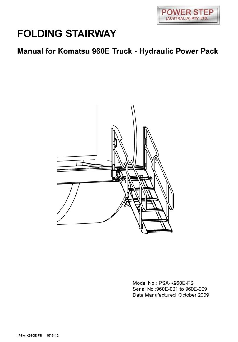
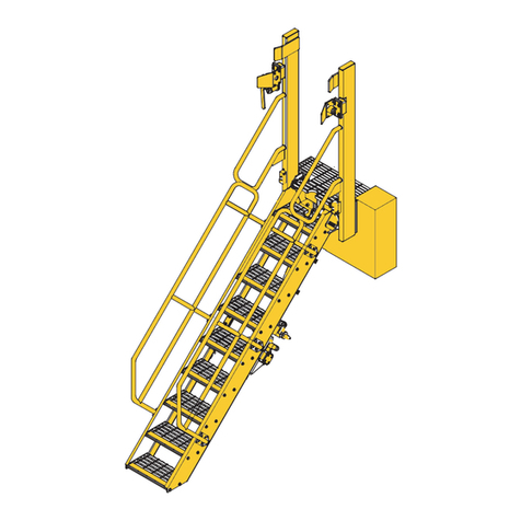
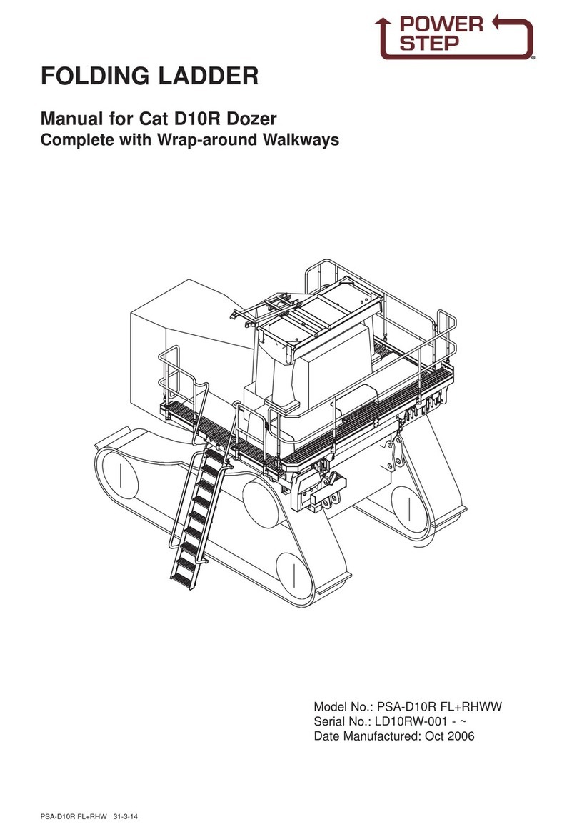
Power Step PSA-773D-FS User manual

FOLDING STAIRWAY
Manual for Cat 773D Truck
Hydraulic Operation
CAT773D 19-12-12
Model No.PSA-773D-FS
Serial No.:773D - ~
Date Manufactured: August 2012

FOLDING STAIRWAY
Caterpillar 773D Truck
Hydraulic Operation
Pg2
CAT773D 19-12-12
CONTENTS
Page 3Section 1 Installation and Mounting instructions
Installation Drawings
12 Section 2 Recommended Maintenance Procedure
13 Section 3 Operating Procedure
Section 4 Drawings and Repair Parts lists
14 4 Assembly Complete
15 4-1 Platform Assembly
Parts List
16 4-2 Fixed Stair Assembly
Parts List
19 4-3 Lower Stair Assembly
Parts List
21 4-4 Hydraulic Cylinder & Plumbing
Parts List
Valve Diagram
23 4-5 Power Pack Assembly
26 4-6 Electrical Controls
Parts List
Wiring Diagrams

Pg3
CAT773D 19-12-12
FOLDING STAIRWAY
Caterpillar 773D Truck
Installation and Mounting Instructions Mounting Bars PS-22683
NOTE
Follow all on-site/Mine lifting and safety procedures when installing
Power Step Landings to Truck.
PROCEDURE
See Drawing PS-22683
1. Remove existing cabin landing and cabin-side ladder.
2. Fit Mounting Bars per View 1. Do not tighten bolts.
3. Fit Top Landing, bolting to the tapped holes in the Mounting Bars.
4. Tighten all the bolts.
VIEW 1.
VIEW 2.

See Drawing 24804 Page 8
1. Fit the Raised Platform to the stair set and truck per Views 1 & 2. The Raised
Platform bolts to the main cabin landing on one side and is supported through
isolators from the radiator enclosure on the other side. Weld the Landing Isolator
Bracket components per Detail 1.1 - the Back to the radiator enclosure and the
Cleat to the Back - in such a position as to make the Platform level and parallel to
the radiator enclosure. Do not burn the rubber isolators while welding.
2. Attach the Flooring Extension to the Raised Walkway as shown in Views 3 & 4, so
it can be folded over towards the engine hood to present a trafficable surface level
with the raised platform or stowed away on top of the raised walkway. Pg4
CAT773D 19-12-12
FOLDING STAIRWAY
Caterpillar 773D Truck
Section 1 Installation Instruction Drawings PS-24802/3/4
Front Bolting Pad
PROCEDURE
See Drawing 24802 Page 5
1. Mount and weld the Front Bolting Pad and Mounting Gussets to the front bumper,
located per View 1.2. Weld per Detail 3 - Preliminary Welding.
Note that this preliminary welding is required to temporarily support the stair during
early stages of the installation procedure. The welding must be upgraded to its'
final specification later in the installation.
2. Check that the dimension shown in Views 1.1 & 1.3, (the distance between the
alignments of the Return Edge of the cabin landing and the face of the Front Bolting
Pad) is measures 130 +/- 10 on the truck. If it does not measure 130 +/- 10, contact
Power Step - some rectification will be required.
3. Check that the dimension shown in View 1.2, (the distance between the alignments
of the face of the cabin landing frame where the stair fits and the end face of the
front bumper) measures 125 +/- 10 on the truck. If it does not measure 125 +/- 10,
contact Power Step - some rectification will be required.
See Drawing 24803 Page 6
1. Fit the Stair Assembly (24 390) to the Front Bolting Pad per
View 1 Stair Installation and to the Landing per View 2.0 Stair/Landing Connection
and Detail 2.1 Isolators
2. Bolt the Support Plate underneath the top of the stair per View 3.0.
Locate the end Bolting Pad against the end of the bumper per Detail 3.1
and tack weld in place.
3. Fully weld the bolting pads to the bumper per Drg 24 389
NOTE
Follow all on-site/Mine lifting and safety procedures when installing
Power Step Landings to Truck.

Pg5
CAT773D 19-12-12
FOLDING STAIRWAY
Caterpillar 773D Truck
Section 1 Installation Instruction Drawings PS-24802
Front Bolting Pad
VIEW 1.2
VIEW 3
VIEW 2
VIEW 1.3
VIEW 1.1
Welding: All Cat SP to AS1554 unless
specifically directed otherwise.

Pg6
CAT773D 19-12-12
FOLDING STAIRWAY
Caterpillar 773D Truck
Section 1 Installation Instruction Drawings Landing PS-24803
See Procedure notes Page 4
VIEW 3.0 DETAIL 3.1 DETAIL 2.1
VIEW 4
VIEW 1

Pg7
CAT773D 19-12-12
FOLDING STAIRWAY
Caterpillar 773D Truck
Section 1 Installation Instruction Drawings PS- 24389
Welding of Bolting Pads
Welding: All Cat SP to AS1554 unless
specifically directed otherwise.

Pg8
CAT773D 19-12-12
FOLDING STAIRWAY
Caterpillar 773D Truck
Section 1 Installation Instruction Drawings PS- 24804
Raised Walkway
NOTE
Follow all on-site/Mine lifting and safety procedures
when installing Power Step Landings to Truck.
See Procedure notes Page 4
VIEW 4
VIEW 3
VIEW 2
DETAIL 1.1
DETAIL 1.2

Pg9
CAT773D 19-12-12
FOLDING STAIRWAY
Caterpillar 773D Truck
Section 1 Installation Instruction Drawings Handrails PS- 24805
PROCEDURE
See Drawing 24802 Page 10
1. Fit all the handrails to the stair set per View 1. Note that Bolting Pads for the
Bonnet Handrail are to be welded in locations to suit on the front of the radiator
surround. Note also, the posts of the Bonnet Handrail are to be lengthened or
shortened as required to give a top rail height of about 950 above the engine hood.
2. Fit the Power Unit per View 1.
3. Fit the Landing Shield to the front of the Raised Walkway per View 1.
4. Fit the Buffer Socket and Mounting/s to the truck bumper per drg 24 390
5. Adjust the handrail vibration buffers, Views 2 & 3 and Detail 4: The stair set is
fitted with rubber bumpers to reduce vibration in the handrails. Adjust the bumpers
so they bear firmly on their adjacent handrails.Trim the fingers of the bumper
mountings if they are likely to snare clothing and cause tripping etc or by protruding
into the walking path of users of the stair might present a danger or inconvenience
to the users of the stair.
NOTE
Follow all on-site/Mine lifting and safety procedures when installing
Power Step Landings to Truck.
Pg10
CAT773D 19-12-12
FOLDING STAIRWAY
Caterpillar 773D Truck
Section 1 Installation Instruction Drawings Handrails PS- 24805
VIEW 1 HANDRAILS
DETAIL 4
VIEW 3
VIEW 3
See Procedure notes Page 9

Pg11
CAT773D 19-12-12
FOLDING STAIRWAY
Caterpillar 773D Truck
Section 1 Installation Instruction Drawings Buffer Bracket PS- 24390
PROCEDURE
Fit Buffer Socket & Mounting 24 371 in suitable position to receive Buffer when Stair
is stowed. Pad 24 371 01 welds to truck bumper behind hinged stair.
Before locating and welding Pad to bumper, bolt Socket Bracket to Pad with bolts in
slots so Bracket is as high as possible relative to Pad, that is, with adjustment
available in slot to allow lowering of bracket on Pad when required to accommodate
future wear in the buffer hinges and cylinder pins, bushes etc.
The Pad and Bracket can then be hung on the buffer (with the lower stair in it is
fully raised, vertical stowed position) to establish the position of the Pad on the
bumper. Adjust so stair is tight in raised position, not swinging with the truck's
movement.

Daily Visually check stairway and structure for damage, loose components,
handrails, etc.
Check for any oil leaks
Notify the appropriate supervisor for any observed damage or malfunction.
500 Hours
Check main mounting bolts for torque.
Check oil levels and bushes for wear.
Thoroughly check all electrical wiring for damage & replace as necessary.
Grease all nipples and moving parts.
Repeat daily check as above.
5000 Hours
Check and inspect all main bolts on stairway system.
Re-torque if required.
Repeat daily check as above.
Drain and refill Hydraulic tanks & hoses.
Bleed system before use.
Check for wear and replace damaged or worn parts.
Check wiring and electrical components for damage.
Grease all nipples and moving parts
Pg12
CAT773D 19-12-12
FOLDING STAIRWAY
Caterpillar 773D Truck
Section 2 Recommended Maintenance Procedure

Pg13
CAT773D 19-12-12
FOLDING STAIRWAY
Caterpillar 773D Truck
Section 3 Operating Procedure
To Lower Ladder (from the machine)
Position machine in a level, safe area, away from the work face, whenever possible.
Apply park brake and lower engine speed to idle.
Check that the area below the Ladder Access System is clear of people and
obstacles, and lower ladder by operating the two position air switch adjacent
to the ladder, to the down position by pressing the switch down.
If the truck is parked on uneven ground, the bottom of the stairway may touch the
ground before the ladder is in the fully lowered position.
Should this occur, descend the ladder with caution.
To Raise Ladder
Ascend the ladder onto the landing of the truck.
Ensure the area around the ladder is clear of people and standing to the side, clear
of the area the handrails and ladder raises into, operate the air switch to the
raise position (up).
The ladder is now raised and stored.
OPERATING NOTES
NOTE: FLOW CONTROL VALVE ADJUSTMENT:
The valve should be positioned to restrict the flow and speed of the Power Step when
lowering. Adjust the knob on top of the valve by turning left or right (clockwise) when the
step is being lowered, until it is lowering at a safe and reasonable speed.
When it is adjusted, lock the adjusting knob by tightening the grub screw located on the
side of the knob.
NOTE: MAGNETIC 'GO' SWITCH ADJUSTMENT:
The switch target trigger area is located on the opposite side and end from the cable entry
point on the switch. Once it is mounted to the switch bracket, adjust the switch in or out
from the stair steel trigger point, to be within 3mm - 10mm from touching each other when
the stair is in the desired rest position.
[DO NOT EXCEED 10MM DISTANCE BETWEEN THE SWITCH AND STRIKER PLATE].
Test by raising and lowering the Power Step a couple of times and adjust again if
necessary.

Pg14
CAT773D 19-12-12
FOLDING STAIRWAY
Caterpillar 773D Truck
Section 4 Assembly Complete PSA-773D-FS

Pg15
CAT773D 19-12-12
FOLDING STAIRWAY
Caterpillar 773D Truck
Section 4-1 Platform Assembly PS-22671A
See Parts List Page 16

Pg16
CAT773D 19-12-12
FOLDING STAIRWAY
Caterpillar 773D Truck
Section 4-1 Platform Assembly PS-22671
See Drawing Page 15
Item Part No. Part Name Qty
1
2
3
4
5
5A
6
7
8
9
10
11
12
13
14
15
16
17
18
18A
19
20
21
22
23
24
25
26
-
27
PS-22671
PS-22663
PS-22681
PS-22680-98
PS-22680-99
PS-22680-97
PS-22670
PS-22670-06
PS-22672-99
PS-22672-98
PS-22666-01
PS-22666-99
PS-34103
PS-40002
PS-23261
PS-22680-08
CPS-M16X75ZP
CPS-M12X35ZP
CPS-M12X30ZP
CPS-M12X25ZP
CPS-M12X20ZP
CPS-M10X30ZP
CPS-M16NZP
CPS-M12NZP
CPS-M10NN
CPS-M16WH
CPS-M12WH
CPS-M10WH
-
PS-24396
TOP LANDING
RAISED PLATFORM
HANDRAIL -TOP LANDING
HANDRAIL-RAISED WALKWAY
HANDRAIL-BONNET
BONNET TOEBOARD(supplied loose)
MIRROR POST
SPACER-MIRROR POST
SIDE MOUNTING BAR
FRONT MOUNTING BAR
LANDING ISOLATOR PLATE
LANDING ISOLATOR BRACKET
BUSH-RUBBER (Mackay M169)
BUFFER (Insul-840-99725)
LANDING SHIELD
BOLTING PAD
BOLT-M16 x 75
BOLT-M12 x 35
BOLT-M12 x 30
BOLT-M12 x 25
BOLT-M12 x 20
BOLT-M10 x 30 c/sunk
NUT-M16
NUT-M12
NUT-M10 NYLOC
WASHER-HARDENED-M16
WASHER-HARDENED-M12
WASHER-HARDENED-M10
-
FLOORING EXTENSION
1
1
1
1
1
1
1
1
1
1
1
1
4
1
1
2
4
30
30
12
8
2
4
34
2
8
115
2
-
1

Pg17
CAT773D 19-12-12
FOLDING STAIRWAY
Caterpillar 773D Truck
Section 4-2 Fixed Stair Assembly PS-23253A
See Parts List Page 18

Pg18
CAT773D 19-12-12
FOLDING STAIRWAY
Caterpillar 773D Truck
Section 4-2 Fixed Stair Assembly PS-23253A
See Drawing Page 17
Item Part No. Part Name Qty
1
1A
1B
2
3
4
5
6
7
8
9
10
11
11A
12
13
14
15
16
17
18
19
20
21
22
23
24
25
26
27
28
PS-23253
PS-22665
PS-23266
PS-23265
PS-23264
PS-24380
PS-22266
PS-22678
PS-22678-07
PS-24380-05
PS-22238
PS-40002
PS-23262
PS-24374
PS-21930A
PS-22233-05
CPS-M24X60ZP
CPS-M20X30ZP
CPS-M16X45ZP
CPS-M16X20ZP
CPS-M12X120ZP
CPS-M12X50ZP
CPS-M12X40ZP
CPS-M12X30ZP
CPS-M12X20ZP
CPS-M16NZP
CPS-M12NZP
CPS-M24WH
CPS-M20WH
CPS-M16WH
CPS-M12WH
LANDING & FIXED STAIR FABRICATION
STAIR ATTACHMENT BRACKET
POWER UNIT BRACKET
OUTER HANDRAIL-FIXED STAIR
INNER HANDRAIL-FIXED STAIR
STAIR SUPPORT PLATE
TREAD
STAIR MOUNTING ARM
BOLTING PAD-STAIR MOUNTING ARM
BOLTING PAD
BRACKET-GO SWITCH
HANDRAIL BUMPER
BRACKET-HANDRAIL BUMPER-(long)
BRACKET-HANDRAIL BUMPER
ISOLATOR MOUNTING ASSEMBLY
ACTUATOR ATTACHMENT
BOLT-M24 x 60
BOLT-M20 x 30
BOLT-M16 x 45
BOLT-M16 x 20
BOLT-M12 x 120
BOLT-M12 x 50
BOLT-M12 x 40
BOLT-M12 x 30
BOLT-M12 x 20
NUT-M16
NUT-M12
WASHER-HARDENED-M24
WASHER-HARDENED-M20
WASHER-HARDENED-M16
WASHER-HARDENED-M12
1
1
2
1
1
1
5
1
1
1
1
4
2
2
2
1
4
4
4
4
2
12
14
34
4
4
54
4
4
12
116

Pg19
CAT773D 19-12-12
FOLDING STAIRWAY
Caterpillar 773D Truck
Section 4-3 Lower Stair Assembly PS-24373A
See Parts List Page 20

Pg20
CAT773D 19-12-12
FOLDING STAIRWAY
Caterpillar 773D Truck
Section 4-3 Lower Stair Assembly PS-24373A
See Drawing Page 19
Item Part No. Part Name Qty
1
2
3
4
5
6
7
8
9
10
11
12
13
14
15
16
17
18
19
20
21
22
23
24
25
-
26
26A
27
28
PS-24373
PS-23465
PS-24376
PS-24375
PS-22266
PS-22233-03
PS-22233-02
PS-22233-01
PS-22383
PS-40001
PS-24371
PS-22233-04
PS-22246
PS-22246-05
CPS-M16X25ZP
CPS-M12X70ZP
CPS-M12X50ZP
CPS-M12X30ZP
CPS-M12X35ZP
CPS-M8X50ZP
CPS-M12NZP
CPS-M8NN
CPS-M16WH
CPS-M12WH
CPS-M8WH
-
PS-24384-01
PS-24384-02
PS-23263
PS-24371-01
BOTTOM STAIR FABRICATION
LADDER EXTENSION
OUTER HANDRAIL-LOWER STAIR
INNER HANDRAIL-LOWER STAIR
TREAD (Inc. one on Extension)
HINGE PLATE SPACER
HINGE CHEEK PLATE
SWITCH TARGET
BUFFER ARM
BUFFER
BUFFER SOCKET & MOUNTING
HINGED STAIR ACTUATOR ATTACHMENT
HINGE PIN
HINGE BUSH
BOLT-M16 x 25
BOLT-M12 x 70
BOLT-M12 x 50
BOLT-M12 x 30
BOLT-M12 x 35
BOLT-M8 x 50 (pin keeper bolt)
NUT-M12
NUT-NYLOC-M8
WASHER-HARDENED-M16
WASHER-HARDENED-M12
WASHER-HARDENED-M8
-
POST PACKERS (not shown)
GO SWITCH POST PACKER (not shown)
HANDRAIL SPACERS (not shown)
BOLTING PAD
1
1
1
1
5
1
4
1
1
1
1
1
2
2
4
10
6
34
2
2
52
2
4
104
4
-
6
1
4
1
This manual suits for next models
1
Table of contents
Other Power Step Ladder manuals

Power Step
Power Step LeTourneau L1850 User manual

Power Step
Power Step PSA-EX5500-FRS User manual

Power Step
Power Step PSA-K930E-FS User manual

Power Step
Power Step PSA-EX2500-FRS User manual

Power Step
Power Step PSA-EX3600-FRS User manual

Power Step
Power Step Caterpillar 854G User manual

Power Step
Power Step Cat D10R Dozer User manual

Power Step
Power Step Komatsu 960E User manual

Power Step
Power Step D10T User manual

Power Step
Power Step PSA-D11R-FL User manual