BOSSCO BE-5B User manual

oB0ss
BASS
MULTIPLE
EFFECTS
5
SPECIAL
SELECTED
EFFECTS
FOR
BASSISTS
|
BE
5B
Owner’s
Manual
a)
1BOSS
BE-5B
BASS
MUU
cea
Thank
you,
and
congratulations
on
your
choice
of
the
BOSS
BE-5B
Bass
Multiple
Effects
unit.
;
:
The
BE-5B
is
a
multi-purpose
effects
unit
equipped
with
all
five
of
the
effects
most
often
needed
with
bass
guitars.
In
order
to
make
good
use
of
all
the
features
available
to
you,
and
be
able
to
continue
using
the
unit
for
many
years
with
confidence,
please
completely
read
this
Owner's
Manual
before
you
start
using
it.
@
IMPORTANT
NOTES
e
When
you
make
any.connections
with
other
devices,
always
turn
off
the
power
to
all
equipment
first.
This
will
help
in
preventing
malfunc-
tion,
and
darnage
to
speakers.
®
Do
not
force
the
unit
to
share
the
same
power
outlet
as
one
used
for
distortion
producing
devices
(such
as
motors,
variable
lighting
devices).
Be
sure
to
use
a
separate
power
outlet.
®
Before
using
the
AC
adaptor,
always
make
certain
the
voltage
of
the
available
power
supply
conforms
to
its
rating.
e
Do
not
place
heavy
objects
onto,
step
on,
or
otherwise
risk
causing
damage
to
the
power
cord.
@
Whenever
you
disconnect
the
AC
adaptor
from
the
outlet,
always
grasp
it
by
the
plug,
to
prevent
internal
damage
to
the
cord
and
the
hazard
of
possible
short
circuits.
®
If
the
unit
not
to
be
used
for
a
long
period
of
time,
unplug
the
cord
from
the
socket.
e
Avoid
using
or
the
unit
in
the
following
places,
as
damage
could
result.
©
Place
subject
to
extremes
in
temperature.
(Such
as
under
direct
sunlight,
near
heating
units,
above
equipment
generating
heat,
etc.)
©
Places
near
water
and
moisture.
(Baths,
washrooms,
wet
floors,
etc.)
Places
otherwise
subject
to
high
humidity.
©
Dusty
environments.
©
Places
where
high
levels
of
vibration
are
produced.
Copyright
©
1989
by
ROLAND
CORPORATION
Alt
rights
reserved.
No
part
of
this
publication
may
be
reproduced
in
.
any
form
without
the
permission
of
ROLAND
CORPORATION.
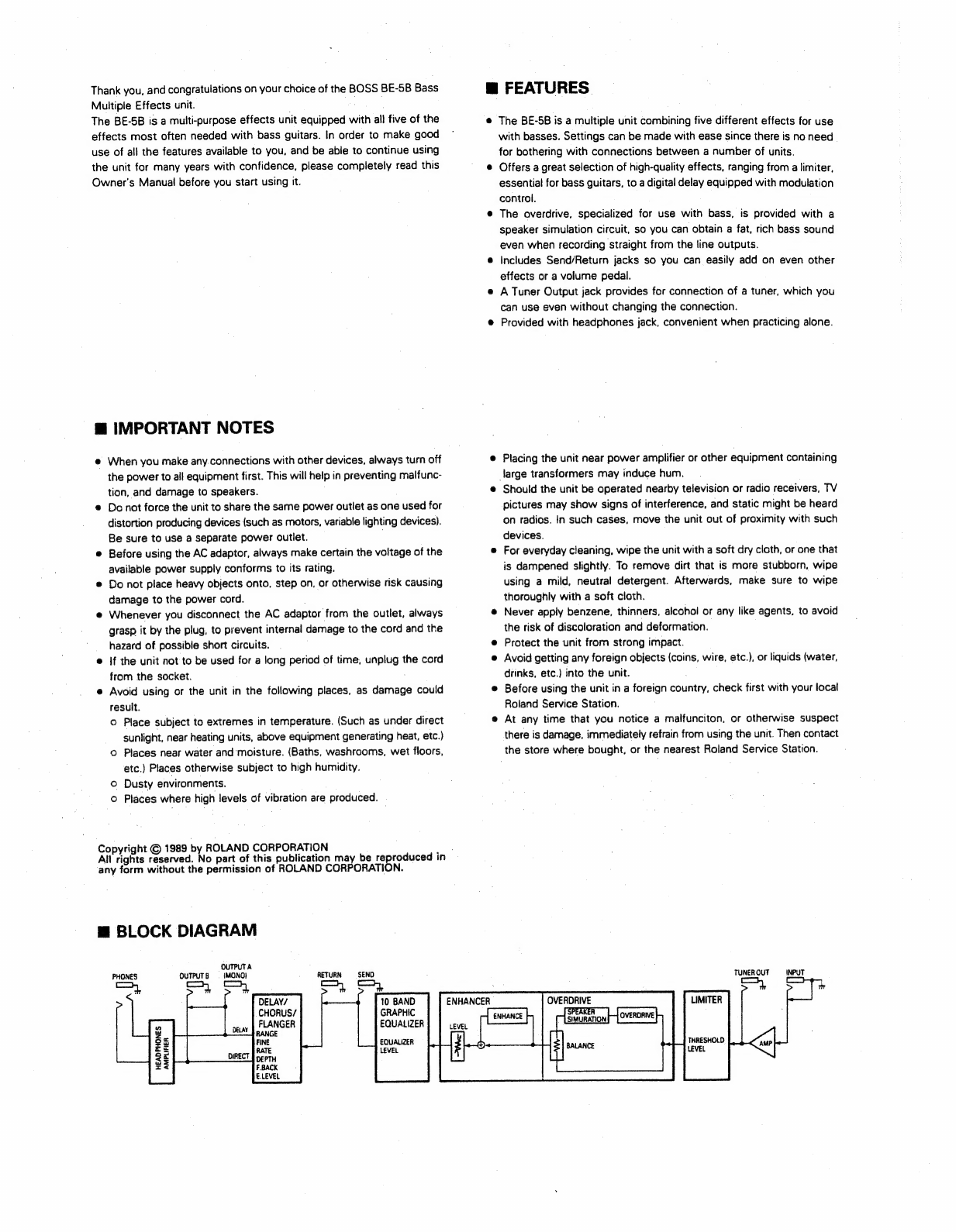
m
BLOCK
DIAGRAM
QUTPUTA
.
PHONES
OUTPUTB
=
(MONO}
.
RETURN
SEND
10
BAND
GRAPHIC
EQUALIZER
EQUALIZER
LEVEL
HEADPHONES
AMPLIFIER
m
FEATURES.
The
BE-58
is
a
multiple
unit
combining
five
different
effects
for
use
with
basses.
Settings
can
be
made
with
ease
since
there
is
no
need
-
for
bothering
with
connections
between
a
number
of
units.
Offers
a
great
selection
of
high-quality
effects,
ranging
from
a
limiter,
essential
for
bass
guitars,
to
a
digital
delay
equipped
with
modulation
control.
The
averdrive,
specialized
for
use
with
bass,
is
provided
with
a
speaker
simulation
circuit,
so
you
can
obtain
a
fat,
rich
bass
sound
even
when
recording
straight
from
the
line
outputs.
Includes
Send/Return
jacks
so
you
can
easily
add
on
even
other
effects
or
a
volume
pedal.
A
Tuner
Output
jack
provides
for
connection
of
a
tuner,
which
you
can
use
even
without
changing
the
connection.
Provided
with
headphones
jack,
convenient
when
practicing
alone.
Placing
the
unit
near
power
amplifier
or
other
equipment
containing
large
transformers
may
induce
hum.
Should
the
unit
be
operated
nearby
television
or
radio
receivers,
TV
pictures
may
show
signs
of
interference,
and
static
might
be
heard
on
radios.
In
such
cases,
move
the
unit
out
of
proximity
with
such
devices.
For
everyday
cleaning,
wipe
the
unit
with
a
soft
dry
cloth,
or
one
that
is
dampened
slightly.
To
remove
dirt
that
is
more
stubborn,
wipe
using
a
mild,
neutral
detergent.
Afterwards,
make
sure
to
wipe
thoroughly
with
a
soft
cloth.
Never
apply
benzene,
thinners,
alcohol
or
any
like
agents,
to
avoid
the
risk
of
discoloration
and
deformation.
Protect
the
unit
from
strong
impact.
Avoid
getting
any
foreign
objects
(coins,
wire,
etc.),
or
liquids
(water,
drinks,
etc.)
into
the
unit.
Before
using
the
unit
in
a
foreign
country,
check
first
with
your
local
Roland
Service
Station.
At
any
time
that
you
notice
a
malfunciton,
or
otherwise
suspect
there
is
damage,
immediately
refrain
from
using
the
unit.
Then
contact
the
store
where
bought,
or
the
nearest
Roland
Service
Station.
TUNER
OUT
INPUT
—
OVERDRIVE
LIMITER

@
SAMPLE
SETTINGS
MROCK
A
sound
that
fits
nght
in
with
the
current
rock
scene.
The
trick
Is
in
using
just
the
right
touch
of
overdrive
MMETAL
With
the
overdrive
providing
a
little
dis-
tortion,
the
equalizer
boosts
the
lower
range
to
make
a
fat
sound
that
is
just
right
for
heavy
metal.
@FLANGING
METAL
The
overdrive
puts
out
a
good
measure
of
distortion
along
with
a
lot
of
wailing
fram
the
flanger
to
add
up
to
a
really
strong
flanged
sound.
M@
METAL
SOLO
A
long
delay
provides
a
sound
good
for
melodious
phrasing.
MCHOPPER
With
the
limiter
smoothing
all
the
peaks.
the
enhancer
and
equalizer
create
a
sound
with
an
impressive
attack
BJAZZ
Equalizer
used
to
raise
the
lower
range
and
bring
out
the
feel
of
a
wood
bass.
SLOW
BALLAD
With
chorus
applied,
and
the
equalizer
used
to
raise
the
lower
range,
a
sound
filled
with
fantasy
is
created.
In
addition,
clarity
is
preserved
by
raising
the
upper
range
with
the
enhancer
and
equalizer.
Great
for
solos.
MSAMBA
The
equalizer
is
used
to
emphasize
the
middle
range,
and
the
enhancer
cleans
up
the
profile.
Suttable
for
rhythmical
songs.
FEEDBACK
*
E
LEvEet
RATE
OEPTH
Sa
FEEOBACK
RANGE
nS
83)
1S
250
500
&
\
f
r
TORTS
Heli
oo
&
LEVEL
RATE
DEPTH
thi
wh
FEEDBACK
6
OG
©
LEVEL
RaTe
DEPTH
RSRSAEUUUULUIEUS
FEEORACK
FINE
5S
61
#126
250
(
‘a
)
Ce
E
GEVEL
aie
QEPTH
aD
Trim
a
a)
BALANCE
qepeebeeeed
ed
FEEOBACK
a
RATE
DEPTH
€.
LEVEL
THT
PL
ars
Fae
€
LEVEL
RATE
FEEDBACK
NS
63
128
250
S00
PI
PP
€
LEVEL
RATE
BALANCE
FEEDRACK
ENHANCER
€
LeveL
RATE
BAL
ANCE
©)
DeLAvrchonus
/FLANGER
|
=
10
BAND
GRAPHIC
EQUALIZER
Is
®
ENHANCER
/
OVERDRIVE
aay

@
OPERATION
m@
CONNECTION
Po
vic
{>
Amplifier
Amplifier
OUTPUT
A
OUTPUT
B
weut
TUNER
Out
SEND
RETURN
A
CUTPUT
8
PHONES
wpe
pert
©
OUBOSS
OO
OO
OF
OE.
AY
(MONO)
DHRECT
J
TUNER
OUT
SEND
RETURN
PHONES
Tuner
(TU-12/TU-125
etc.:
optional)
INPUT
OUTPUT
External
Effect
Device
AC
Adaptor
(FV-5OL
etc.:
optional)
(PSA-120,
220
or
240:
supplied)
Headphones
(RH-12
etc.
:
optional)
Amplifier
Amplifier
=
OUTPUT
=
B
©
aC
TF
TUNER
OUT
AC
Adaptor
PHONES
(PSA-120,
220
or
240:
supplied)
Tuner
(TU-12/TU-12S
etc.:
optional)
|
{
apes
_
=
alereh-
Headphones
(RH-12
etc.:
optional)
©)
power
©
Indicator
lights.
1.
Once
the
bass
and
amplifier
have
been
connected
as
shown
in
the
illustration,
connect
the
supplied
AC
adaptor.
The
unit
is
ready
for
use
when
Its
Power
*
Make
sure
volume
is
raised
after
connection
is
finished.
BASS
MULTIPLE
EFFECTS
|
SPLCIAL, SELECTED
EFFECTS
FOR
Maemo
2.
Each
knob
is
set
so
it
appears
as
shown
in
“PANEL
DESCRIPTIONS”.
3.
Make
the
settings
for
each
of
the
effects.
@
Use
the
Pedal
Switch
to
turn
“on”
the
effect
that
is
to
be
set.
(When
on,
the
Effects
Indicators
for
that
effect
will
light.)
*
All
other
effects
need
to
be
“off.”
1
a
@
While
referring
to
"SAMPLE
SETTINGS”,
under
"PANEL
DESCRIPTIONS",
make
settings
as
desired.
@
Repeat
the
above
procedures
and
make
settings
for
the
other
effects.

§
PANEL
DESCRIPTIONS
DELAY/CHORUS/FLANGER
The
digital
delay
is
equipped
with
controls
for
modulation.
Can
be
used
to
fatten
a
sound
by
adding
slightly
delayed
elements,
or
provide
the
effects
of
long
delays.
Since
the
BE-5B
employs
a
digital
delay,
there
is
no
deterioration
in
the
quality
of
the
source
sound.
Settings
for
delay
time
are
accepted
consecutively
from
2
to
500
msec.
In
addition,
thanks
to
the
modulation
function,
chorus
and
flanging
effects
can
be
obtained.
(See
EXAMPLES
FOR
SETTING
_
DELAY/CHORUS/FLANGER.)
@
RANGE:
Delay
Time
Range
knob
Adjusts,
in
combination
with
the
FINE
knob,
the
delay
time
(amount
of
delay
with
respect
to
the
source
sound).
The
RANGE
knob
accepts
8
levels
of
possible
settings
for
the
delay
time.
iC:
Range
providing
longer
delay
times.
Used
to
set
for
a
delay
providing
a
recognizable
delayed
sound.
[|
Range
providing
shorter
delay
times.
Used
to
get
a
short
delay,
which
can
be
used
to
fatten
up
sound.
@
DEPTH:
Modulation
Depth
knob
Adjusts
the
depth
of
the
modulation
when
the
digital
delay
is
used
to
obtain
chorus
or
flanging
effects.
[C+]:
Modulation
is
deepened.
[7]:
Modulation
is
lessened.
At
the
minimum,
no
modulation
is
obtained.
@
FINE:
Delay
Time
Fine
knob
Provides
for
fine
adjustment
of
the
delay
time
set
with
the
RANGE
knob.
The
available
range
provides
for
a
multiplier
of
from
0.5
to
1.0
times
the
value
set
with
the
RANGE
knob.
IC:
Delay
time
is
lengthened.
[¥]:
Delay
time
is
shortened.
@
RATE:
Moduration
Rate
knob
Adjusts
the
rate
of
the
modulation
when
the
digital
delay
is
used
to
obtain
chorus
or
flanging
effects.
IQ:
The
modulation
rate
is
made
faster.
[4]:
The
modulation
rate
is
made
slower.
*
With
the
Modulation
Depth
knob
set
too
low,
no
effect
results.
@
FEEDBACK:
Feedback
knob
Adjust
the
amount
of
the
delayed.
sound
that
is
repeated
(amount
of
feedback).
IQ:
increases
amount
of
feedback.
{#>|:
Decreases
amount
of
feedback.
When
set
at
the
minimum,
one
repetition
takes
place
(there
is
a
single
delay).
*
Take
caution,
since
oscillation
can
occur
if
the
amount
of
the
FEEDBACK
knob
sets
too
high.
@
EFFECT
LEVEL:
Effect
Level
knob
Adjust
the
level
of
the
delayed
sound.
{C:
The
delayed
sound
is
increased.
When
at
the
maximum,
the
delayed
sound
and
the
direct
sound
are
identical.
[I]:
The
delayed
sound
is
decreased.
When
at
the
minimum,
only
the
direct
sound
is
output;
no
output
of
the
delayed
sound
takes
place.
@
Power
indicator
Lights
up
when
the
supplied
AC
adaptor
is
saneeeiad
indicating
that
the
unit
is
ready
for
use.
;
@
Effects
indicators
Light
up
for
an
effect
that
is
on
(When
its
effects
can
be
‘Obteinge)
Allow
you
to
confirm
the
on/off
status
of
each
effect.
©.
Pedal
Switch
Switch
each
effect
on
or
off.
@®
Input
Jack
Accepts
connection
of
a
bass
guitar.
@
Tuner
Out
Jack
From
the
Tuner
Out
jack,
tuner-use
bass
guitar
signals
are
output
at
all
times.
Tuning
can
be
carried
out
at
any
time
simply
by
connecting
a
tuner.
@
Send
Jack
@
Return
Jack
The
Send/Return
jacks
provide
for
the
connection
of
an
external
device,
such
as
an
external
effects
device.
An
effects
unit
is
connected
between
the
graphic
equalizer
and
the
delay.
*
Refer
to
the
diagram
when
making
connection.
{Example
Setup]
A
volume
pedal
(FV-50L)
can
be
connected.
Then,
using
a
volume
altering
technique,
you
can
obtain
a
natural
decay
of
the
sound
while
having
the
delayed
sound
remain
(when
the
unit
is
set
to
the
Dalay
mode).
if
you
set
the
volume
of
the
pedal
to
the
“0”
position,
tuning
can
be
performed
without
getting
the
sound
from
the
amplifier.

10
BAND
GRAPHIC
EQUALIZER
O
"10
BAND
GRAPHIC
EQUALIZER
The
10-band
graphic
equalizer
provides
ad-
justment
within
the
range
of
+
188dB
for
each
band.
@
LEVEL
CONTROL:
Level
Control
slider
Sets
the
overall
level
output
by
the
equal-
izer.
Should
be
adjusted
so
there
is
no
difference
in
level
when
the
effect
is
turned
on/off.
|
[
t
]:
The
overall
level
output
by
the
equal-
izer
increases.
|
{
|
]:
The
overall
level
output
by
the
equal-
izer
decreases.
EQUALIZER
CONTROL:
Equalizer
Control
slider
Provides
for
boosting
or
cutting
the
sound
for
each
band.
.
[
t
|:
Boosts
the
sound
only
for
the
band
for
which
the
control
slider
is
moved.
[
|
|:
Cuts
the
sound
only
for
the
band
for
which
the
control
slider
is
moved.
Peep
aC
mate:
DEPTH
E,
CEVEL
lO)
10
BAND
GRAPHIC
EQUALIZER
Cy}
ennancen
-overonve
|
C))
LIMITER
)
OELAY/
CHORUS
/FLANGER
—
Dae
I
|
‘PUT
TUNER
OUT
©
©®
a
@®
o
®
®@&
®

ENHANCER/OVERDRIVE
This
effect
combines
both
an
enhancer,
that
provides
greater
definition
for
the
sound;
and
overdrive
to
add
distortion
to
the
sound.
They
can
be
set
in
any
variety
of
ways
to
suit
most
any
type
of
music.
In
addition,
the
overdrive
con-
tains
a
speaker
simulation
circuits,
thus
allowing
direct
connection
to
a
mixer
or
other
device.
@
DRIVE:
Drive
knob
Adjusts
the
amount
of
tube-amp
distortion
produced
by
the
overdrive.
IQ:
Distortion
becomes
greater,
sound
gets
heavier.
[Ol
Distortion
decreases.
When
turned
all
the
way
to
the
left
If],
dis-
tortion
disappears,
and
only
speaker
simulation
will
be
in
effect.
@
BALANCE:
Balance
knob
Adjusts
the
balance
between
the
normal
sound
and
the
overdriven
sound.
Settings
covering
any
number
of
possible
combinations
can
be
made.
IC]:
The
proportion
of
the
overdriven
sound
(speaker
simulation)
increases.
[4];
The
normal
sound's
proportion
becomes
greater.
*
When
set
a
either
right
[Ca
or
left
[7]
extremes,
the
effect
of
the
counterpart
is
eliminated.
*
When
wishing
to
use
the
speaker
simulation
circuit
alone,
set
the
drive
knob
to
its
minimum
[>],
and
the
balance
knob
to
the
maximum
[Q].
@
ENHANCER:
Enhancer
knob
Enhances
the
definition
of
each
sound,
and
provides
more
presence.
IQ):
Enhancer
effect
becomes
greater.
.
|]:
Enhancer
effect
is
lessened.
When
at
left
[%}]
extreme,
no
effect
is
obtained.
©
LEVEL:
Level
knob
.
Adjusts
the
level
of
sound
volume
for
the
Enhancer/Overdrive.
Should
be
~
adjusted
so
there
is
no
difference
in
level
when
the
effect
is
turned
on/off.
[C’l:
The
volume
of
effected
sound
increases.
|]:
The
volume
of
effected
sound
decreases.
When
at
left
>]
extreme,
no
sound
will
be
heard.
@
Output
A
Jack
(monaural)
@®
Output
B
Jack
Jacks
used
to
connect
an
amplifier.
LIMITER
By
limiting
excessive
input
(in
excess
of
peak),
erratic
volume
changes
are
eliminated,
and
the
sound
is
more
balanced,
and
freer
from
unwanted
distortion.
When
used
with
styles
like
slapping
with
a
bass
guitar,
the
peak
sound
is
controlled
better
and
sound
balance
improves.
@
THRESHOLD:
Threshold
Knob
Sets
the
level
at
which
it
starts
limiting
the
input
signal.
Whenever
a
signal
that
surpasses
the
level
set
here.
has
been
input,
the
output
is
limited
to
the
level
set.
Signals
lower
than.
this
level
(Threshold
Level)
will
continue
to
be
output.
{Q]:
Threshold
level
is
raised.
[1]:
Threshold
level
is
lowered;
effect
of
limiter
is
increased.
@
LEVEL:
Level
knob
Sets
the
overall
level
output
by
the
limiter.
Should
be
set
so
there
is
no
difference
in
level
when
the
effect
is
turned
on/off.
[Q:
The
overall.jevel
output
by
the
limiter
increases.
{I:
The
overall
level
output
by
the
limiter
decreases.
*
When
used
with
one
amp,
connect
to
Output
A
(monaural).
*
When
used
with
two
amps,
and
with
the
DELAY/CHORUS/FLANGER
at
“off”.
the
same
sound
will
be
output
from
both
amps.
With
DELAY/CHORUS/FLANGER
at
“on”,
the
delay
sound
will
be
output
from
Output
A,
and
the
direct
sound,
will
be
output
from
Output
B.
@)
Headphones
Jack
Accepts
connection
of
headphones.
Volume
is
adjusted
using
the
connected
instrument.
*
Take
caution,
since
asillation
can
occur
if
the
amount
of
the
gain
sets
too
high
@
Cord
Clip
Prevents
the
AC
adaptor
plug
from
being
pulled
cut
accidentally.
The
cord
should
be
fixed
to
the
unit
as
shown
in
the
illustration.
@
AC
Adaptor
Jack
Accepts
connection
of
supplied
AC
Adaptor
(PSA-120,
220
or
240)
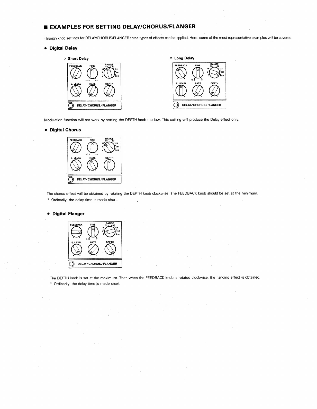
m
EXAMPLES
FOR
SETTING
DELAY/CHORUS/FLANGER
‘Through
knob
settings
for
DELAY/CHORUS/FLANGER
three
types
of
effects
can
be
applied.
Here,
some
of
the
most
representative
examples
will
be
covered.
®
Digital
Delay
©
Short
Delay
Oo
Long
Delay
FEEDBACK
FEEDBACK
E.
LEVEL
RATE
OEPTH
E.
LEVEL
RATE
DEPTH
©)
_DELAY/CHORUS/
FLANGER
C)
_DELAY/CHORUS/FLANGER
Modulation
function
will
not
work
by
setting
the
DEPTH
knob
too
low.
This
setting
will
produce
the
Delay
effect
only.
e
Digital
Chorus
FEEDBACK
FINE
x05
€.
LEVEL
RATE
_
DEPTH
©)
DELAY/
CHORUS
/
FLANGER
|
The
chorus
effect
will
be
obtained
by
rotating
the
DEPTH
knob
clockwise.
The
FEEDBACK
knob
should
be
set
at
the
minimum.
*
Ordinarily,
the
delay
time
is
made
short.
e
Digital
Flanger
FEEDBACK
E.
LEVEL
RATE
DEPTH
(©)
DELAY/CHORUS/FLANGER
The
DEPTH
knob
is
set
at
the
maximum.
Then
when
the
FEEDBACK
knob
is
rotated
clockwise,
the
flanging
effect
is
obtained.
*
Ordinarily,
the
delay
time
is
made
short.

@
SPECIFICATIONS
Controls
«1»
Limiter
Threshold,
Level
«2»
Enhancer/Overdrive
Drive,
Balance,
Enhancer,
Level
«3»
10-Band
Graphic
Equalizer
Level
Control,
10
Equalizer
Controls
«<4))
Delay/Chorus/Flanger
Range,
Fine,
Modulation
Rate,
Modulation
Depth,
Feedback,
Effect
Level.
Switches
Pedals:
4
Indicators
Effect:
4
Power:
1
Jacks
Input,
Tuner
Out,
Send,
Return,
Output
A
(monaural),
Output
B,
Phones,
AC
adaptor.
Electrical
Characteristics
|
©
Input
Rated
Input
Level:
~20dBm
Input
Impedance:
1MQD
©
Tuner
Out
Rated
Output
Level:
-20dBm
Output
Impedance:
2kN
Output
Load
Impedance:
more
than
20k
©
Effect
Send
Rated
Output
Level:
-20dBm
Output
Impedance:
1kQ
Output
Load
Impedance:
more
than
10kN
©
Effect
Return
Rated
Input
Level:
-20dBm
Input
Impedance:
47k2
©
Digital
Delay
Process:
Analog
Logarithmic
Compression,
Plus
12-bit
Quantization
Delay
Time:
2msec.
to
500msec.
Frequency
Response:
Delay:
20Hz
to
15kHz
+3dB)
Residual
Noise:
Less
Than
~90dBm
(IHF-A)
with
Fine
x
0.5
Note:
Any
settings
that
place
all
knobs
at
their
maximum
can
result
in
a
range
of
problems,
such
as
noise
and
howling.
(Gerat.
Typ.
Bezeichnung)
funk-entstért
ist.
WARNING
~—
CLASS
8B
1
acest
CLASSE
B
ree
rs
This
booklet
1s
avaiable
from
the
U.S
Government
Printing
Office,
Washington,
D.C
.
20402.
Stock
No
004-000-00345-4
Bescheinigung
des
Herstellers/Importeurs
Hiermit
wird
bescheinigt,
daB
der/die/das
BOSS
BASS
MULTIPLE
EFFECTS
BE-5B
Pare
rer
rere
a
ere
ee
ey
(Amtsbilattvertugung)
Der
Deutschen
Bundespost
wurde
das
Inverkehrbringen
dieses
Gerates
angezeigt
und
die
Berechtigung
zur
Uberpritung
der
Serie
auf
Einhaltung
der
Bestimmungen
eingeraumt.
Roland
Corporation
Osaka/Japan
Name
des
Herstellers/Imponeurs
RADIO
AND
TELEVISION
INTERFERENCE
This
equipment
has
been
ventied
to
compiy
with
the
iimits
for
a
Class
8
computing
device.
pursuant
to
Subpart
J.
of
Part
15.
of
FCC-rules
Operaton
with
non-certhed
or
non-venhed
equipment
ts
thely
to
result
in
interterance
to
radio
and
TV
reception
The
equipment
described
in
this
manual
generates
and
uses
radio
frequency
energy
[fit
is
nol
stalled
and
used
property,
that
ts,
19
Strict
accordance
with
our
instructions.
it
may
Cause
interference
with
radio
and
tetewsion
reception
This
equipment
has
been
tested
and
found
to‘compty
with
the
ints
tor
a
Class
B
computing
device
in
accordance
with the
speciicatians
in
Subpart
J.
of
Part
15,
of
FCC
Rules.
These
rulus
are
designed
to
provide
reasonable
protection
against
such
a
Mterference
ira
rasidential
installation.
However.
there
6
no
guarantee
thal
the
interference
will
not
occur
in
a
particular
instatabon
if
tus
equipment
does
cause
interference
to
radio
or
television
reception.
which
can
be
determined
by
turring
the
equipment
on
and
off,
the
user
1s
encouraged
to
try
!0
correct
the
interference
dy
the
following
measure
®
Disconnect
other
dewces
and
ther
inpuvoutpul
cables
one
at
a
time
If
the
intederence
stops.
itis
Caused
by
either
the
other
device
or
its
vO
cable
These
devices
usually
require
Roland
designated
shiekled
VO
cables.
For
Roland
devices.
you
can
obtain
ihe
proper
shueided
cable
from
your
dealer
For
non
Roland
devices,
contact
the
manufacturer
or
deaier
for
assistance
:
it
your
equipment
does
cause
interference
to
radio
or
television
reception,
you
can
try
to
Correct
the
interference
by
using
une
oF
more
at
the
following
measures.
®
Turn
tne
TV
of
radio
antenna
unti
the
interference
stops
@
Move
the
equipment
to
ane
side
of
the
other
of
the
TV
or
radio
@
Move
the
equipment
farther
away
trom
the
TV
or
racko
:
®
Plug
the
equipment
into
an
outlet
that
is
an
a
diferent
cucu
than
the
TV
of
radio
{That
is.
make
certain
the
equipment
and
(he
radio
or
television
set
are
on
citcuits
Ton
walled
by
different
circuit
breakers
or
fuses.?
©
Consider
installing
a
roottop
television
antenna
wilh
coawal
Cable
lead-in
between
the
anienna
and
TV
If
necessary.
you
should
consull
your
dealet
ot
an
expenenced
racho-telewision
technician
for
additional
suggestions.
You
may
tind
helpful
the
tolloming
booklet
prepared
by
the
Federal
Communications
Commission
“How
to
Identily
and
Resolve
R-io
—
TV
interference
Problems”
NOTICE
This
digital
apparatus
does
not
exceed
the
Class
B
limits
for
radio
noise
emissions
set
out
in
the
Radio
interference
Regulations
of
the
Canadian
Department
of
Communications.
AVIS
Cet
appareil
numérique
ne
dépasse
pas
les
limites
de
la
classe
B
au
niveau
des
émissions
de
bruits
tadioélectriques
fixes
|
dans
je
Réglement
des
signaux
parasites
par
le
ministere
canadien
des
Communications.
in
Ubereinstimmung
mit
den
Bestimmungen
der
ee
ee
©
Output
A/B
Rated
Output
Level:
-20dBm
Output
Impedance:
1k
Output
Load
Impedance:
more
than
10kN
o
Phones
Output
Impedance:
470
Optimum
Headphones
Impedance:
8
to
100
*
OdBm=0.775V
Power
Supply:
9
VDC
(PSA-120,
220
or
240
AC
Adaptor,
Supplied)
Current
Draw:
150mA
(max.)
Dimensions:
300(W)
x
40(H)
x200(D)
mm.
11-13/16"(W)
x
1-5/8°(H)
x
7-7/8"(D)
Weight:
950g/2lb,
202
(not
including
AC
Adaptor)
Supplied
Accessories:
Owner's
Manual,
AC
Adaptor
Options:
Chromatic
Tuner
(TU-12,
TU-12S),
Volume
Pedal
(FV-50L)
*
The
specifications
for
this
product
are
subject
to
change
without
prior
notice,
in
the
interest
of
improvement.
For
West
Germany
For
the
USA
7.
For
Canada
Nee
jotenteimtianetee
a
Hitler
OSs
Products
of
Roland

Roland
|
7524922900
Will
oBoss
Table of contents
Other BOSSCO Music Pedal manuals

BOSSCO
BOSSCO BF-2 Flanger User manual

BOSSCO
BOSSCO FV-300H User manual

BOSSCO
BOSSCO Acoustic Simulator AC-2 Operating and maintenance manual

BOSSCO
BOSSCO HF-2 User manual

BOSSCO
BOSSCO RC-500 User manual

BOSSCO
BOSSCO LMB-3 User manual

BOSSCO
BOSSCO ME-90 User manual

BOSSCO
BOSSCO LS-2 User manual

BOSSCO
BOSSCO ME-25 Setup guide

BOSSCO
BOSSCO DS-1W User manual

BOSSCO
BOSSCO DS-1X User manual

BOSSCO
BOSSCO Chorus CE-3 User manual

BOSSCO
BOSSCO ME-30 User manual

BOSSCO
BOSSCO FW-3 Foot Wah User manual

BOSSCO
BOSSCO NS-2 Noise Suppressor User manual

BOSSCO
BOSSCO RC-500 User manual

BOSSCO
BOSSCO VE-500 User manual

BOSSCO
BOSSCO PH-2 Operating and maintenance manual

BOSSCO
BOSSCO DS-1 User manual

BOSSCO
BOSSCO PS-3 User manual


