BOSSCO KATANA-50 MkII User manual
This Owner’s Manual applies to the KATANA-50 MkII,
KATANA-50 MkII EX, KATANA-100 MkII, KATANA-100/212 MkII,
KATANA-HEAD MkII, KATANA-Artist MkII, and
KATANA-Artist MkII HEAD.
Explanations for specic models are distinguished by an icon
(example: 100/212, HEAD only ).
Owner’s Manual
Guitar Amplier
KATANA-50 MkII
KTN-50 2
50 W output, 30 cm (12 inch) speaker
KATANA-50 MkII EX
KTN50 2EX
50 W output, 30 cm (12 inch) speaker
KATANA-100 MkII
KTN-100 2
100 W output, 30 cm (12 inch) speaker
KATANA-100/212 MkII
KTN-212 2
100 W output, 30 cm (12 inch) speaker x 2
KATANA-HEAD MkII
KTN-HEAD 2
100 W output, 12 cm (5 inch) speaker
KATANA-50 MkII
KATANA-50 MkII EX
KATANA-100 MkII
KATANA-100/212 MkII
KATANA-HEAD MkII
KATANA-Artist MkII
KATANA-Artist MkII HEAD
KATANA-Artist MkII
KTN-ART 2
100 W output, 30 cm (12 inch) speaker
KATANA-Artist MkII HEAD
KTN-ART2HD
100 W output
2
WARNING
Make sure that the power cord is grounded
Connect mains plug of this model to a
mains socket outlet with a protective
earthing connection.
To completely turn o power to the unit, pull out
the plug from the outlet
Even with the power switch turned o, this
unit is not completely separated from its
main source of power. When the power
needs to be completely turned o, turn
o the power switch on the unit, then
pull out the plug from the outlet. For this reason, the
outlet into which you choose to connect the power
cord’s plug should be one that is within easy reach and
readily accessible.
Secure a sucient amount of space at the setup
location
Since this unit normally emits a slight
amount of heat, make sure to secure
sucient space around it, as shown below.
Front Side
20 cm (8 in.)
or greater
20 cm (8 in.)
or greater
30 cm (12 in. )
or greater 5 cm (2 in.)
or greater 15 cm (6 in.)
or greater
Do not disassemble or modify by yourself
Do not carry out anything unless you are
instructed to do so in the owner’s manual.
Otherwise, you risk causing malfunction.
Do not repair or replace parts by yourself
Be sure to contact your dealer, a Roland
service center, or an ocial Roland dealer.
For a list of Roland service centers and
ocial Roland dealers, refer to the Roland
website.
WARNING
Do not use or store in the following types of
locations
• Subject to temperature extremes (e.g.,
direct sunlight in an enclosed vehicle,
near a heating duct, on top of heat-
generating equipment); or are
• Damp (e.g., baths, washrooms, on wet
oors); or are
• Exposed to steam or smoke; or are
• Subject to salt exposure; or are
• Exposed to rain; or are
• Dusty or sandy; or are
• Subject to high levels of vibration and shakiness;
or are
• Placed in a poorly ventilated location.
Do not place in an unstable location
Otherwise, you risk injury as the result of
the unit toppling over or dropping down.
Connect the power cord to an outlet of the correct
voltage
The unit should be connected to a power
supply only of the type described as
marked on the rear side of unit.
Use only the supplied power cord
Use only the attached power cord. Also,
the supplied power cord must not be used
with any other device.
Do not bend the power cord or place heavy objects
on it
Otherwise, re or electric shock may result.
Avoid extended use at high volume
Use of the unit at high volume for
extended periods of time may cause
hearing loss. If you ever experience any
hearing loss or ringing in the ears, you
should immediately stop using the unit
and consult a specialized physician.
Do not allow foreign objects or liquids to enter
unit; never place containers with liquid on unit
Do not place containers containing liquid
(e.g., ower vases) on this product. Never
allow foreign objects (e.g., ammable
objects, coins, wires) or liquids (e.g., water
or juice) to enter this product. Doing so
may cause short circuits, faulty operation,
or other malfunctions.
WARNING
Turn o the unit if an abnormality or malfunction
occurs
In the following cases, immediately turn
o the power, remove the power cord
from the outlet, and contact your dealer, a
Roland service center, or an ocial Roland
dealer for service.
• The power cord has been damaged; or
• If smoke or unusual odor occurs; or
• Objects have fallen into, or liquid has been spilled
onto the unit; or
• The unit has been exposed to rain (or otherwise has
become wet); or
• The unit does not appear to operate normally or
exhibits a marked change in performance.
For a list of Roland service centers and ocial Roland
dealers, refer to the Roland website.
Be cautious to protect children from injury
Always make sure that an adult is on hand
to provide supervision and guidance when
using the unit in places where children
are present, or when a child will be using
the unit.
Do not drop or subject to strong impact
Otherwise, you risk causing damage or
malfunction.
Do not share an outlet with an unreasonable
number of other devices
Otherwise, you risk overheating or re.
Do not use overseas
Before using the unit in overseas, consult
with your retailer, the nearest Roland
service center, or an authorized Roland
distributor.
For a list of Roland service centers and ocial Roland
dealers, refer to the Roland website.
Don’t block ventilation openings
Don’t allow the unit’s ventilation openings
to be blocked by a newspaper, tablecloth,
curtains, or similar objects.
Don’t place burning objects on the unit
Don’t place any burning object
(such as a candle) on the unit.
Be aware of weather conditions
Use the apparatus in moderate climates.
USING THE UNIT SAFELY
Before using this unit, carefully read “IMPORTANT SAFETY INSTRUCTIONS” (inside front cover),“USING THE UNIT SAFELY”(p. 2), and “IMPORTANT NOTES” (p. 3). After reading,
keep the document(s) where it will be available for immediate reference.
© 2022 Roland Corporation
Used for instructions intended to alert the
user to the risk of injury or material
damage should the unit be used
improperly.
* Material damage refers to damage or
other adverse effects caused with
respect to the home and all its
furnishings, as well to domestic animals
or pets.
Used for instructions intended to alert the
user to the risk of death or severe injury
should the unit be used improperly.
The symbol alerts the user to things that must be
carried out.The specific thing that must be done is
indicated by the design contained within the circle. In the
case of the symbol at left, it means that the power-cord
plug must be unplugged from the outlet.
The symbol alerts the user to important instructions or
warnings.The specific meaning of the symbol is
determined by the design contained within the triangle.In
the case of the symbol at left, it is used for general
cautions, warnings, or alerts to danger.
The symbol alerts the user to items that must never be
carried out (are forbidden).The specific thing that must
not be done is indicated by the design contained within
the circle. In the case of the symbol at left, it means that
the unit must never be disassembled.
About WARNING and CAUTION Notices About the Symbols
ALWAYS OBSERVE THE FOLLOWING

3
IMPORTANT NOTES
IMPORTANT NOTES
CAUTION
When disconnecting the power cord, grasp it by the
plug
To prevent conductor damage, always
grasp the power cord by its plug when
disconnecting it.
Periodically clean the power plug
An accumulation of dust or foreign objects
between the power plug and the power
outlet can lead to re or electric shock.
At regular intervals, be sure to pull out
the power plug, and using a dry cloth,
wipe away any dust or foreign objects that may have
accumulated.
Disconnect the power plug whenever the unit will
not be used for an extended period of time
Fire may result in the unlikely event that a
breakdown occurs.
CAUTION
Route all power cords and cables in such a way as
to prevent them from getting entangled
Injury could result if someone were to
trip on a cable and cause the unit to fall
or topple.
Avoid climbing on top of the unit, or placing heavy
objects on it
Otherwise, you risk injury as the result of
the unit toppling over or dropping down.
Never connect/disconnect a power plug if your
hands are wet
Otherwise, you could receive an electric
shock.
Disconnect all cords/cables before moving the unit
Before moving the unit, disconnect the
power plug from the outlet, and pull out all
cords from external devices.
CAUTION
Before cleaning the unit, disconnect the power
plug from the outlet
If the power plug is not removed from the
outlet, you risk receiving an electric shock.
Whenever there is a threat of lightning, disconnect
the power plug from the outlet
If the power plug is not removed from the
outlet, you risk causing malfunction or
receiving an electric shock.
KATANA-50 MkII EX
Do not remove the speaker grille and speaker
Do not remove the speaker grille and
speaker by any means. Speaker is not user
replaceable. Shock hazardous voltages and
currents are present inside the enclosure.
Power Supply
• Do not connect this unit to same electrical outlet
that is being used by an electrical appliance that
is controlled by an inverter or a motor (such as a
refrigerator, washing machine, microwave oven, or
air conditioner). Depending on the way in which
the electrical appliance is used, power supply noise
may cause this unit to malfunction or may produce
audible noise. If it is not practical to use a separate
electrical outlet, connect a power supply noise lter
between this unit and the electrical outlet.
Placement
• Using the unit near power ampliers (or other
equipment containing large power transformers)
may induce hum. To alleviate the problem, change
the orientation of this unit; or move it farther away
from the source of interference.
• This unit may interfere with radio and television
reception. Do not use this unit in the vicinity of such
receivers.
• Noise may be produced if wireless communications
devices, such as cell phones, are operated in the
vicinity of this unit. Such noise could occur when
receiving or initiating a call, or while conversing.
Should you experience such problems, you should
relocate such wireless devices so they are at a
greater distance from this unit, or switch them o.
• When moved from one location to another where
the temperature and/or humidity is very dierent,
water droplets (condensation) may form inside
the unit. Damage or malfunction may result if you
attempt to use the unit in this condition. Therefore,
before using the unit, you must allow it to stand for
several hours, until the condensation has completely
evaporated.
• Depending on the material and temperature of the
surface on which you place the unit, its rubber feet
may discolor or mar the surface.
• Do not place containers or anything else containing
liquid on top of this unit. Also, whenever any liquid
has been spilled on the surface of this unit, be sure
to promptly wipe it away using a soft, dry cloth.
Maintenance
• Never use benzine, thinners, alcohol or solvents of
any kind, to avoid the possibility of discoloration
and/or deformation.
Repairs and Data
• Before sending the unit away for repairs, be sure to
make a backup of the data stored within it; or you
may prefer to write down the needed information.
Although we will do our utmost to preserve the
data stored in your unit when we carry out repairs,
in some cases, such as when the memory section
is physically damaged, restoration of the stored
content may be impossible. Roland assumes no
liability concerning the restoration of any stored
content that has been lost.
Additional Precautions
• Any data stored within the unit can be lost as the
result of equipment failure, incorrect operation, etc.
To protect yourself against the irretrievable loss of
data, try to make a habit of creating regular backups
of the data you’ve stored in the unit.
• Roland assumes no liability concerning the
restoration of any stored content that has been lost.
• Use a reasonable amount of care when using the
unit’s buttons, sliders, or other controls; and when
using its jacks and connectors. Rough handling can
lead to malfunctions.
• When disconnecting all cables, grasp the connector
itself—never pull on the cable. This way you will
avoid causing shorts, or damage to the cable’s
internal elements.
• A small amount of heat will radiate from the unit
during normal operation.
• To avoid disturbing others nearby, try to keep the
unit’s volume at reasonable levels.
• When disposing of the packing carton or cushioning
material in which this unit was packed, you must
observe the waste disposal regulations that apply to
your locality.
• Do not use connection cables that contain a built-in
resistor.
Intellectual Property Right
• ASIO is a trademark and software of Steinberg Media
Technologies GmbH.
• This product contains eParts integrated software
platform of eSOL Co.,Ltd. eParts is a trademark of
eSOL Co., Ltd. in Japan.
• Roland and BOSS are either registered trademarks
or trademarks of Roland Corporation in the United
States and/or other countries.
• Company names and product names appearing
in this document are registered trademarks or
trademarks of their respective owners.
4
Panel Descriptions
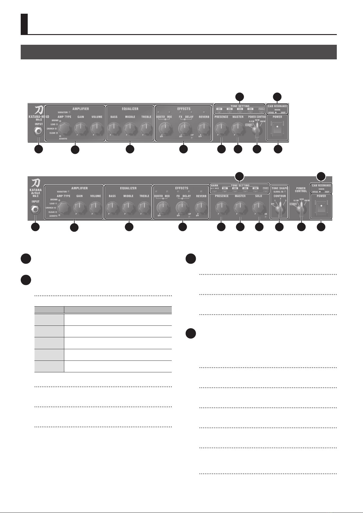
1 INPUT jack
Connect your electric guitar here.
2 AMPLIFIER
[AMP TYPE] knob
Selects the amp type. All provided amp types are original.
Type Explanation
BROWN A lead sound with an edge inherited from the BOSS WAZA
brown sound.
LEAD Dierent gain settings allow this sound to cover a wide
range from crunch to high-gain.
CRUNCH A fat crunch sound that faithfully responds to the nuances
of your picking.
CLEAN A clean and natural sound. In conjunction with BOOSTER, it
can be used for solo or lead.
ACOUSTIC A dedicated acoustic guitar amp that supports connection
of an acoustic guitar.
[VARIATION] button
Switches the AMP TYPE variation.
[GAIN] knob
Adjusts the gain (amount of distortion).
[VOLUME] knob
Adjusts the volume.
3 EQUALIZER
[BASS] knob
Adjusts the sound level of the low-frequency range.
[MIDDLE] knob
Adjusts the sound level of middle-frequency range.
[TREBLE] knob
Adjusts the sound level of the high-frequency range.
4 EFFECTS
Here you can make settings for the built-in eects. For details on
the eect types and settings for each knob, refer to “Using the
Eects” (p. 11).
[BOOSTER] button/knob
Controls distortion-type eects.
[MOD] button/knob
Controls modulation eects.
[FX] button/knob
Controls eects such as wah, tremolo, and octave.
[DELAY] button/knob
Controls delay eect.
[TAP] button
Sets the delay time. When you press this button two or more times,
the delay time is set to the interval between presses.
[REVERB] button/knob
Controls the reverb.
Top Panel/Front Panel
KATANA-50 MkII, KATANA-50 MkII EX, KATANA-100 MkII, KATANA-100/212 MkII, KATANA-HEAD MkII
* The illustration shows the KATANA-HEAD MkII.
* KATANA-50 MkII/KATANA-50 MkII EX does not have a [PRESENCE] knob, [CAB RESONANCE] switch, nor does it have TONE SETTING buttons [CH3] and [CH4].
* KATANA-100 MkII does not have a [CAB RESONANCE] switch.
8
2
1 3 4 5 6 7 10
9
KATANA-Artist MkII, KATANA-Artist MkII HEAD
2
1 3 4 5 6 711 12 10
8 9

5
Panel Descriptions
5 [PRESENCE] knob 100, 100/212, HEAD, Artist, Artist HEAD only
Adds lustrous outline to the mid- and high-frequency range. This is
eective when you want to improve the denition of the sound.
6 [MASTER] knob
Adjusts the overall volume.
7 [POWER CONTROL] switch
Lets you switch the output level of the power amp according to
your location or needs. By selecting “STANDBY” you can mute the
sound while leaving the unit powered-on.
This lets you mute the amp without changing the volume or other
settings when you leave the stage, such as between sets of your live
performance.
8 TONE SETTING
Here you can store or recall sounds that you’ve set up on the panel.
50, 50 EX
You can store a total of four sounds.
BANK A CH1, CH2
BANK B CH1, CH2
* With the KATANA-50 MkII EX, you can use CH3 and CH4 by
connecting a GA-FC/GA-FC EX (sold separately).
100, 100/212, HEAD, Artist, Artist HEAD
You can store a total of eight sounds.
BANK A CH1, CH2, CH3, CH4
BANK B CH1, CH2, CH3, CH4
MEMO
To switch between BANK A and BANK B, hold down the [PANEL]
button for approximately one second when any one of the [CH1]–
[CH4] buttons are selected.
The selected [CH1]–[CH4] button blinks, and the bank switches
between BANK A and BANK B. When BANK B is selected, the [PANEL]
button blinks slowly.
* You can’t switch banks while PANEL is selected.
[BANK] button Artist, Artist HEAD only
Switches between BANK A and BANK B.
When BANK B is selected, the [BANK] button is lit.
[CH1]–[CH4] buttons
The [CH1]–[CH4] buttons (
50, 50 EX [CH1] [CH2] buttons) on
the remember the settings of all top panel knobs (except for the
[MASTER] knob) and buttons.
When you press and hold a button for one second, the panel
settings are stored.
* You can make the settings back to the factory state by turning the
power on while holding down the [PANEL] button.
[PANEL] button
Makes the unit sound using the current settings of the panel knobs.
9 [CAB RESONANCE] switch
100/212, HEAD, Artist, Artist HEAD only
Modies the resonance of the speaker cabinet.
Value Explanation
VINTAGE The warm and sweet sound of a vintage cabinet.
MODERN A modern cabinet sound notable for a tight low-end.
DEEP Sound with powerful low-end as well as a distinctive edge.
10 [POWER] switch
Turns the power on/o.
11 SOLO Artist, Artist HEAD only
[SOLO] knob
Adjusts the volume when solo is on.
[SOLO] button
Turns solo on/o.
12 TONE SHAPE Artist, Artist HEAD only
[GLOBAL EQ] button
Turns the global equalizer on/o.
You can also switch between three types of equalizer settings
(green, red, orange).
MEMO
The three types of global equalizer settings can be edited using
dedicated software (p. 11).
These settings cannot be edited from the unit itself.
[CONTOUR] switch
Switches the contour characteristics of the sound.
In addition to “OFF”, you can choose from the three types “1, 2, 3”.
50, 50 EX, 100, 100/212, HEAD only
6
Panel Descriptions
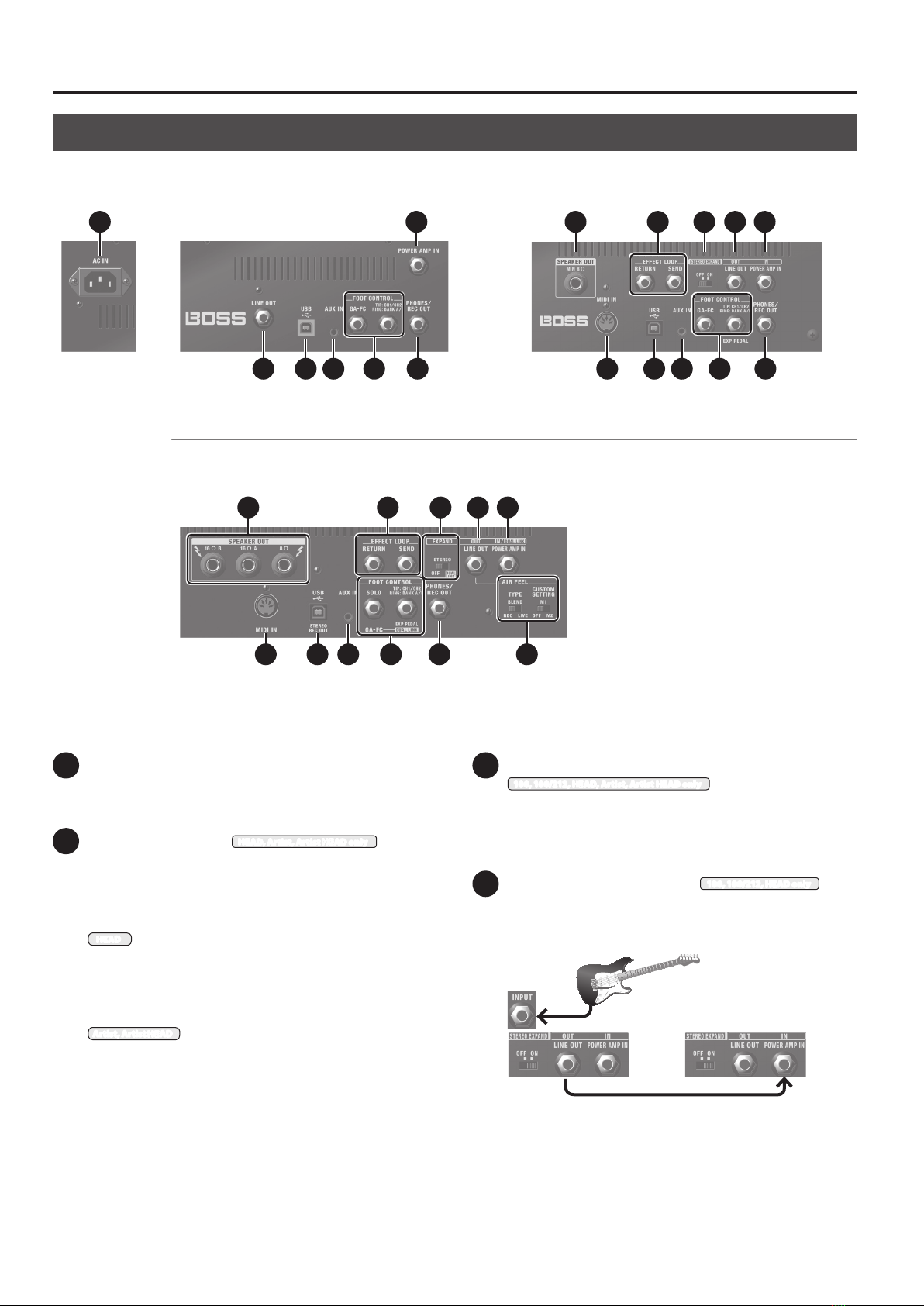
13 AC IN jack
Connect the included power cord.
* Use only the power cord that was included with the unit.
14 SPEAKER OUT jack HEAD, Artist, Artist HEAD only
Connect a speaker box. Only use speaker cable to connect the
speaker. Do not use any shielded cable designed for use with
guitars.
When connecting an external speaker
HEAD
5If a plug is inserted in this jack, no sound will be output from the
KATANA MkII’s own speaker.
5You must use a speaker box that has an input impedance of 8Ω
or higher.
Artist, Artist HEAD
5When the unit is shipped from the factory, the internal speaker
is connected to the 8Ω jack. If a plug is connected to the 8Ω jack,
sound is not output from the 16Ω (A/B) jacks. If you want to use
an external speaker, disconnect the internal speaker’s plug from
the 8Ω jack.
5If you use the 8Ω jack, you must use a speaker box whose input
impedance is 8Ω or higher.
5If you use the 16Ω (A/B) jacks, you must use speaker boxes whose
input impedance is 16Ω or higher.
15 EFFECT LOOP SEND/RETURN jacks
100, 100/212, HEAD, Artist, Artist HEAD only
Connect an external eect device (mono).
Connect the SEND jack to the input of your external eect device,
and connect the output of your external eect device to the
RETURN jack.
16 [STEREO EXPAND] switch 100, 100/212, HEAD only
Two KATANA MkII units can be connected for stereo output.
Stereo connection method
Amp 1
Amp 2
1. From the LINE OUT jack of the amp 1 to which your guitar
is connected, connect to the POWER AMP IN jack of the
amp 2.
2. Turn “ON”the [STEREO EXPAND] switch of both amps.
* The controls of the amp 2 other than the [MASTER] knob and the
[POWER CONTROL] switch do not function.
Rear Panel
KATANA-50 MkII, KATANA-50 MkII EX KATANA-100 MkII, KATANA-100/212 MkII
KATANA-HEAD MkII
* The illustration shows the KATANA-HEAD MkII. The KATANA-100 MkII
and KATANA-100/212 MkII do not have MIDI IN jack and SPEAKER
OUT jacks.
* The illustration shows the KATANA-50 MkII EX. The KATANA-50 MkII
does not have LINE OUT jack and GA-FC jack.
13
* The illustration shows the KATANA-Artist MkII HEAD. The KATANA-Artist MkII does not
have AIR FEEL [TYPE] switch and [CUSTOM SETTING] switch.
KATANA-Artist MkII, KATANA-Artist MkII HEAD
18
2019 21 23
14 16 1715
222017 21
18
2322
2019 21 23 2522
14 1715 24 18
7
Panel Descriptions
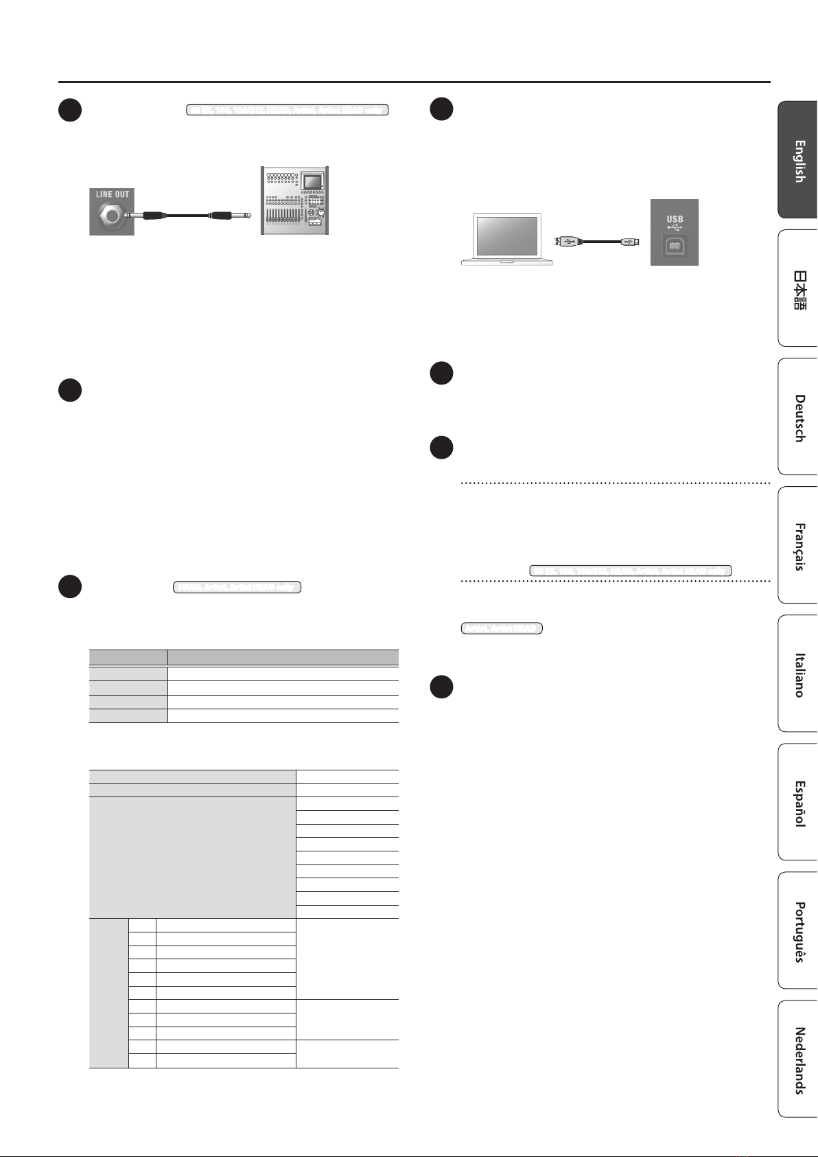
17 LINE OUT jack 50 EX, 100, 100/212, HEAD, Artist, Artist HEAD only
Connect this to your PA system or recorder. You can obtain powerful
guitar amp sound just as if you were playing through the speaker.
Recorder, etc.
You can use this in conjunction with an external PA system, or to
record your performance via direct line while monitoring the sound
from the KATANA MkII’s speaker.
Adjust the output level using the [VOLUME] knob.
Since the [MASTER] knob does not aect the output, you can turn
down the [MASTER] knob so that sound is output to a connected
device without any sound being produced from the amp itself.
* To prevent malfunction and equipment failure, always turn down the
volume, and turn o all the units before making any connections.
18 POWER AMP IN jack
This jack directly inputs a signal to the power amp without passing
it through the preamp of the KATANA MkII. You can use it to input
sound that’s been shaped by an external preamp or by a multi-
eect unit equipped with an amp simulator. If you’re using the
POWER AMP IN jack, the [PANEL] button is lit green.
* Sound that is input to this jack is not aected by controls other than
the [MASTER] knob and the [POWER CONTROL] switch.
* Unless you are using two KATANA MkII units connected in stereo,
leave the [STEREO EXPAND] switch or [EXPAND] switch turned “OFF”.
* The POWER AMP IN jack and the INPUT jack cannot be used
simultaneously. If cables are connected to both, the INPUT jack has
priority.
19 MIDI IN jack HEAD, Artist, Artist HEAD only
You can control this unit from a multi-eect unit or a MIDI foot
controller.
How the MIDI receive channel is specied
Receive channel Operation
CH1 Hold down the [CH1] button while turning the power on.
CH2 Hold down the [CH2] button while turning the power on.
CH3 Hold down the [CH3] button while turning the power on.
CH4 Hold down the [CH4] button while turning the power on.
* Receive channel is set to CH1 when shipped from the factory.
RECOGNIZED RECEIVE DATA
RX CH 1-4
OMNI OFF (xed)
PC
1 (00H): BANK A CH1
2 (01H): BANK A CH2
3 (02H): BANK A CH3
4 (03H): BANK A CH4
5 (04H): PANEL
6 (05H): BANK B CH1
7 (06H): BANK B CH2
8 (07H): BANK B CH3
9 (08H): BANK B CH4
CC
#16 BOOSTER SW
0–63: OFF
64–127: ON
#17 MOD SW
#18 FX SW
#19 DELAY SW
#20 REVERB SW
#21 EFFECT LOOP SW
#80 GA-FC EXP PEDAL 1 (FX)
0–127#81 GA-FC EXP PEDAL 2 (VOLUME)
#82 EXP PEDAL
#83 GA-FC (FS1) 0–63: OFF
64–127: ON
#84 GA-FC (FS1)
* When you operate the knobs in the EFFECTS section, the settings
of the knobs become eective and the above on/o setting will be
discarded.
20 USB Oport
You can use a commercially available USB 2.0 cable to record the
sound of the KATANA MkII into your computer. You can also use
dedicated software to edit the settings of the internal eects (p. 11).
* Do not use a USB cable that is designed only for charging a device.
Charge-only cables cannot transmit data.
You must install the USB driver when connecting the unit to
your computer.
Download the USB driver from the Roland website. For details, refer
to Readme.htm which is included in the download.
https://www.boss.info/support/
21 AUX IN jack
Here you can connect a CD player, audio player, electronic musical
instrument, or similar audio source, and listen to it while you play
your guitar.
22 FOOT CONTROL
SEL CH1 CH2/EXP PEDAL jack
If you connect a footswitch (sold separately: FS-6, FS-7, or FS-5L),
you can use your foot to switch between BANK A and BANK B and
CH1 and CH2. If you connect an expression pedal (sold separately:
Roland EV-5, BOSS EV-30, FV-500L, FV-500H), you can use your foot
to vary the volume.
GA-FC jack 50 EX, 100, 100/212, HEAD, Artist, Artist HEAD only
You can connect the separately sold GA-FC/GA-FC EX to switch
channels and turn eects on/o.
Artist, Artist HEAD
You can also connect a footswitch (separately sold: FS-5L) as the
SOLO jack, and use it to switch solo on/o.
23 PHONES/REC OUT jack
Connect headphones here. You can obtain powerful guitar sounds
just as if you were playing through the speaker. To adjust the
volume, use the [VOLUME] knob along with the [MASTER] knob.
* If a plug is inserted in this jack, no sound will be output from the
KATANA MkII’s own speaker. This is convenient if you don’t want
loud sound to be produced from the speaker, such as when you’re
practicing at night.
8
Panel Descriptions
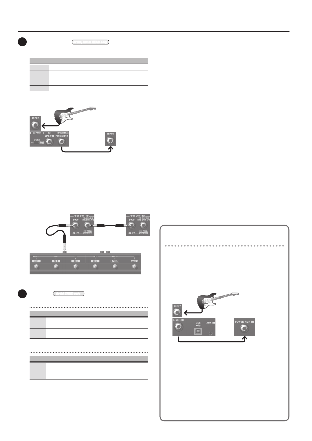
24 [EXPAND] switch Artist, Artist HEAD only
You can connect two KATANA MkII units and use them for stereo
output or as dual amps.
Switch Explanation
OFF Use one KATANA MkII unit by itself.
STEREO
Connect two KATANA MkII units for stereo output.
For details on connections, refer to“Stereo connection method”
(p. 6).
DUAL LINK Connect two KATANA MkII units and use them as dual amps.
Dual amp connections
Amp 1
Amp 2
1. From the POWER AMP IN jack of the amp 1 to which your
guitar is connected, connect to the INPUT jack of the amp 2.
2. Set both amp’s [EXPAND] switch to “STEREO” or“DUAL
LINK”.
GA-FC/GA-FC EX connection
If you connect the GA-FC/GA-FC EX when using a dual amp setup,
you can control the two units simultaneously.
GA-FC
Amp 1 Amp 2
25 AIR FEEL Artist HEAD only
[TYPE] switch
Switch Explanation
REC A distantly-miked sound for recording.
LIVE A close-miked sound for live.
BLEND A sound providing a good blend of closed-miked and
distantlymiked sound that can be broadly used for live or recording.
[CUSTOM SETTING] switch
Switch Explanation
OFF Enables the function you set using the [TYPE] switch.
M1 Select either the M1 or M2 that you congured on the dedicated
software (p. 11) to use.
M2
About the STEREO EXPAND mode
on the KATANA-50 MkII EX
You can connect two KATANA-50 MkII EX units for stereo output
(STEREO EXPAND mode).
1. While holding down the [CH2] and [PANEL] buttons,
turn on both amp 1 and 2.
Stereo connection method
Amp 1
Amp 2
1. From the LINE OUT jack of the amp 1 to which your
guitar is connected, connect to the POWER AMP IN
jack of the amp 2.
* You can use a KATANA-50 MkII (Ver. 2.0 or later) for amp 2.
* Amp 2 operations
When using STEREO EXPAND mode, the [PANEL] button lights
up red, and you can only operate the [MASTER] knob and the
[POWER CONTROL] switch.
* To return to normal LINE output, turn o the power, and then
turn it on again while pressing the [CH2] and [PANEL] buttons.

9
Panel Descriptions
Connecting a Footswitch
Connecting a footswitch (sold separately: BOSS FS-6, FS-7, or FS-5L)
Stereo 1/4”phone type ,
Stereo 1/4”phone type
or
FS-5L
RING
RING
TIP
TIP
RING TIP
FS-6 FS-7
Rear panel
Stereo 1/4”phone type ,
1/4” phone type x 2
or
Switch Explanation
TIP Switches between CH1 and CH2.
RING Switches between BANK A and BANK B.
* The KATANA MkII is compatible with latch-type footswitches (FS-6, FS-
7, FS-5L). If you’re using an FS-6 or FS-7, set the mode of A and B to FS-
5L (LATCH). Momentary-type footswitches (e.g., FS-5U) cannot be used.
Connecting the GA-FC/GA-FC EX
50 EX, 100, 100/212, HEAD, Artist, Artist HEAD only
Connect a stereo cable to the GA-FC jack.
* Always use a stereo cable.
* Use cables that do not contain resistors.
GA-FC
Using the GA-FC/GA-FC EX
You can switch TONE SELECT (CH1–CH4, PANEL). You can also switch
EFFECTS (BOOSTER, MOD, FX, DELAY, REVERB) on/o.
Artist, Artist HEAD
You can long-press the selected [CH1]–[CH4] or [PANEL] switch to switch
solo on/o (the indicator slowly blinks green when solo is on).
If you long-press the [EFFECTS] switch (the indicator blinks), you can
then use the [DELAY] switch to tap-input the delay 1 time, and use the
[REVERB] switch to tap-input the delay 2 time.
Using the expression pedals
If you connect an expression pedal (sold separately: Roland EV-5, BOSS
EV-30, FV-500L, FV-500H), you can use the pedal to vary the volume or
control an eect such as WAH.
GA-FC
Expression Pedal
Jack Explanation
VOLUME Adjusts the volume.
EXP You can control an eect such as WAH.
* You can use dedicated software (p. 11) to assign a function of your
choice to an expression pedal connected to the VOLUME or EXP jack.
Setting MINIMUM VOLUME of an expression pedal
With the [MINIMUM VOLUME] knob of an
expression pedal, you can set the value
for when the pedal is lifted up all the way
(lowest value).
* Use only the specied expression pedal. By connecting any other
expression pedals, you risk causing malfunction and/or damage to the
unit.
Using the footswitches
If a footswitch (sold separately: FS-6, FS-7, or FS-5U) is connected, you can
use it to switch between the TONE SETTING’s BANK A/B, or to set the delay
time (TAP).
1/4” phone type ,1/4” phone type
Jack Explanation
FS1 Switches the TONE SETTING’s BANK A/B.
FS2 Sets the delay time. When you press this button two or more
times, the delay time is set to the interval between presses.
* You can use dedicated software (p. 11) to assign a function of your
choice to a footswitch connected to the FS1 or FS2 jack.
Using the GA-FC/GA-FC EX to switch the BANK
With one of the channels [CH1]–[CH4] selected, hold down the [PANEL]
switch for approximately one second.
The selected [CH1]–[CH4] switch blinks, and the bank switches between
BANK A and BANK B. When BANK B is selected, the [PANEL] button blinks
slowly.
GA-FC
* You can’t switch banks while PANEL is selected.
[MINIMUM
VOLUME] knob

10
Panel Descriptions
Turning the Power On/O
* Once everything is properly connected (p. 4–p. 7), be sure to follow the
procedure below to turn on their power. If you turn on equipment in
the wrong order, you risk causing malfunction or equipment failure.
* Before turning the unit on/o, always be sure to turn the volume down.
Even with the volume turned down, you might hear some sound when
switching the unit on/o. However, this is normal and does not indicate
a malfunction.
1. Make sure that the KATANA MkII’s [MASTER] knob and the
volume of the devices connected to the KATANA MkII are
set to 0.
* Before connecting your instrument to the KATANA MkII’s INPUT
jack, set the [MASTER] knob to the minimum setting (far left).
2. Turn on the KATANA MkII.
3. Turn on the power of the devices connected to the LINE
OUT jack and PHONES/REC OUT jack.
4. Adjust the volume levels for the devices.
Before switching o the power, lower the volume on each of the devices
in your system and then TURN OFF the devices in the reverse order to
which they were switched on.
* If you need to turn o the power completely, rst turn o the unit, then
unplug the power cord from the power outlet.
Refer to“To completely turn o power to the unit, pull out the plug
from the outlet” (p. 2).
Restoring the Factory Settings
Here’s how the settings stored in the KATANA MkII can be returned to
their factory-set condition (factory reset).
1. While holding down the [PANEL] button, turn the power
on.
Each of the EFFECTS buttons continues blinking consecutively from
the left. When the blinking stops, all of the KATANA MkII’s settings
return to the factory-set state.
* It takes approximately 30 seconds for the factory reset to be
completed. Don’t turn o the power while the factory reset is in
progress.

11
Using the Eects
On the KATANA MkII amp, you can use ve types of eect simultaneously.
Eects assigned to each knob when the unit is shipped
Knob Color of the button BOOSTER MOD
Green BANK A BLUES DRIVE CHORUS
BANK B CLEAN BOOST DC-30
Red BANK A OVERDRIVE PHASER 90E
BANK B MID BOOST COMP
Orange BANK A DISTORTION FLANGER 117E
BANK B TREBLE BOOST LIMITER
Knob Color of the button FX DELAY
Green BANK A TREMOLO DIGITAL DELAY
BANK B PHASER 90E SDE-3000
Red BANK A T.WAH ANALOG DELAY
BANK B FLANGER 117E DIGITAL DELAY
Orange BANK A HEAVY OCTAVE TAPE ECHO
BANK B PITCH SHIFTER MODULATE
Knob Color of the button REVERB
Green BANK A PLATE REVERB
BANK B PLATE REVERB
Red BANK A SPRING REVERB
BANK B PLATE REVERB
Orange BANK A HALL REVERB
BANK B HALL REVERB
1. Press the [BOOSTER], [MOD], [DELAY], [FX], or [REVERB]
button to select the eect that you want to use.
Each time you press the button, its color changes.
2. Turn the knob to adjust the depth of the eect.
BOOSTER
depth (outside)
MOD depth
(inside)
FX depth
(outside)
DELAY depth
(inside)
REVERB depth
Making use of the KATANA MkII’s dedicated software
You can connect the amp via USB to your computer, and use it with dedicated software. Using the dedicated software
allows you to do the following:
5Easily download dedicated eects from Boss Tone Central (http://bosstonecentral.com) download site into the amp.
5Edit the eect settings.
5Back up eects and other internal settings, or restore settings from a backup.
You can easily download the dedicated software from our BOSS TONE CENTRAL (http://bosstonecentral.com/) website. For details on how to use
the software, refer to the Readme.htm le that comes with the download.
12
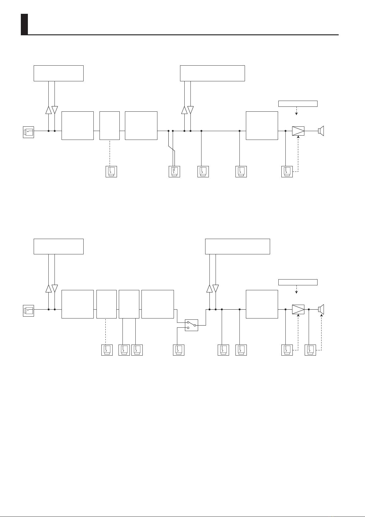
KATANA-50 MkII, KATANA-50 MkII EX
SPEAKER
PHONES/
REC OUT
AUX INEXP PEDAL LINE OUT
(KATANA-50 MkII EX only)
POWER AMP IN
PREAMP EFFECTS MASTER
FOOT
VOLUME
INPUT
POWER CONTROL
MUTE
POWER
AMP
USB
-Secondary (Windows)
-Input/Output 3,4 (Mac)
USB
-Primary (Windows)
-Input 1,2/Stereo Out(1,2) (Mac)
* The signal from the USB port is output
through the LINE OUT jack and the
PHONES/REC OUT jack. This signal is not
output from the speakers.
KATANA-100 MkII, KATANA-100/212 MkII, KATANA-HEAD MkII, KATANA-Artist MkII, KATANA-Artist MkII HEAD
PHONES/
REC OUT
AUX INLINE OUTRETURNSENDEXP PEDAL SPEAKER OUT
(KATANA-HEAD MkII only)
POWER AMP IN
STEREO
EXPAND SW
PREAMP MASTER
FOOT
VOLUME
SEND/
RETURN
INPUT
POWER CONTROL
USB
-Primary (Windows)
-Input 1,2/Stereo Out(1,2) (Mac)
MUTE
MUTE
POWER
AMP
EFFECTS
USB
-Secondary (Windows)
-Input/Output 3,4 (Mac)
SPEAKER
* The signal from the USB port is output
through the LINE OUT jack and the
PHONES/REC OUT jack. This signal is
not output from the speakers.
Block Diagram
13
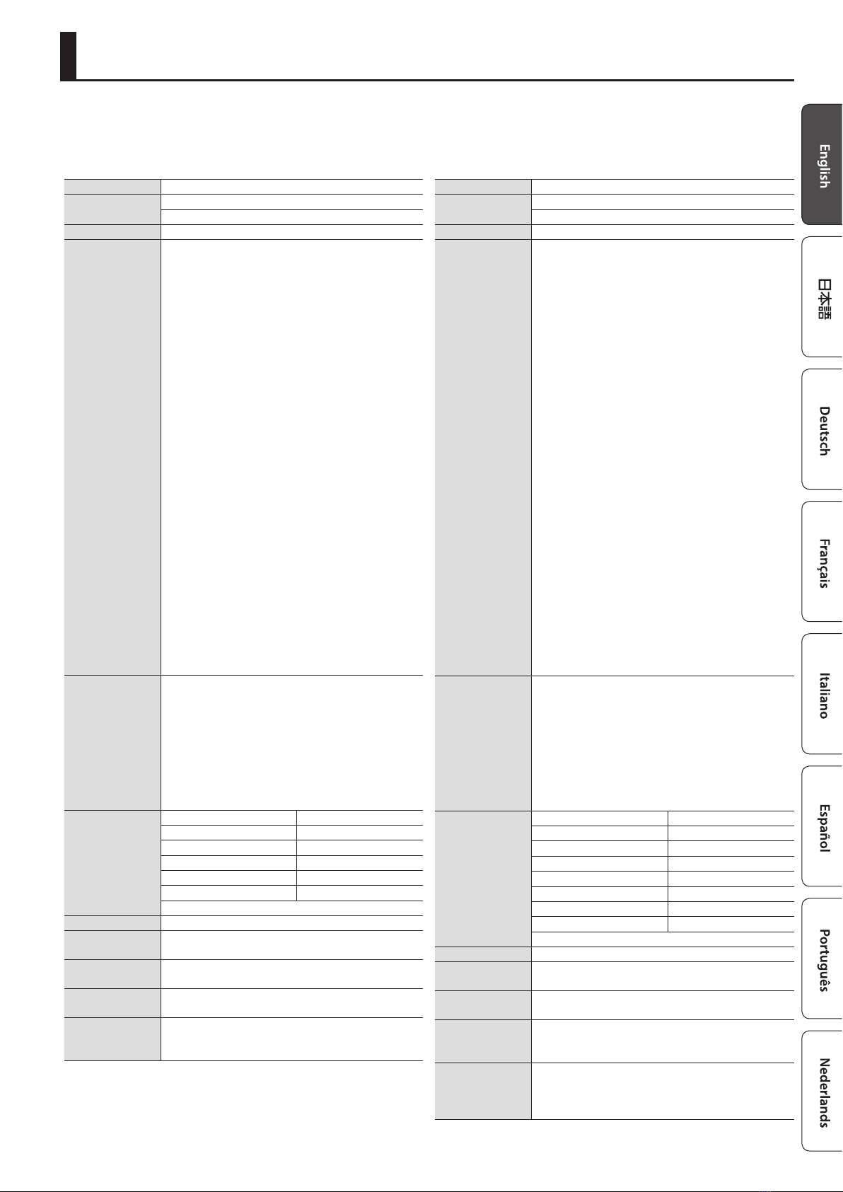
Main Specications
* This document explains the specications of the product at the time that the document was issued. For the latest information, refer to the Roland
website.
KATANA-50 MkII
Rated Power Output 50 W
Nominal Input Level INPUT: -10 dBu (1 MΩ)
AUX IN: -10 dBu (20 kΩ)
Speaker 30 cm (12 inches) x 1
Controls
[POWER] switch
[MASTER] knob
[POWER CONTROL] switch: STANDBY, 0.5 W, 25 W, 50 W
<AMPLIFIER>
[VARIATION] button
[AMP TYPE] knob: ACOUSTIC, CLEAN, CRUNCH, LEAD, BROWN
[GAIN] knob
[VOLUME] knob
<EQUALIZER>
[BASS] knob
[MIDDLE] knob
[TREBLE] knob
<MULTI EFFECT>
[BOOSTER] button
[MOD] button
[FX] button
[DELAY] button
[REVERB] button
[TAP] button
[BOOSTER] knob
[MOD] knob
[FX] knob
[DELAY] knob
[REVERB] knob
<TONE SETTING>
[CH1] button
[CH2] button
[PANEL] button
Indicators
VARIATION
BOOSTER
MOD
FX
DELAY
REVERB
TAP
CH1
CH2
PANEL
Connectors
INPUT jack 1/4-inch phone type
POWER AMP IN jack 1/4-inch phone type
REC OUT/PHONES jack Stereo 1/4-inch phone type
EXP PEDAL/CTL CH1/CH2 jack 1/4-inch TRS phone type
AUX IN jack Stereo miniature phone type
USB port USB B type
AC IN jack
Power Consumption 47 W
Dimensions 470 (W) x 238 (D) x 398 (H) mm
18-9/16 (W) x 9-3/8 (D) x 15-11/16 (H) inches
Weight 11.6 kg
25 lbs 10 oz
Accessories Owner’s Manual
Power cord
Options
(sold separately)
Footswitch: FS-5L, FS-6, FS-7
Expression pedal: EV-30, FV-500L, FV-500H, Roland EV-5
Amplier Stand: BAS-1
* 0 dBu = 0.775 Vrms
KATANA-50 MkII EX
Rated Power Output 50 W
Nominal Input Level INPUT: -10 dBu (1 MΩ)
AUX IN: -10 dBu (20 kΩ)
Speaker 30 cm (12 inches) x 1
Controls
[POWER] switch
[MASTER] knob
[POWER CONTROL] switch: STANDBY, 0.5 W, 25 W, 50 W
<AMPLIFIER>
[VARIATION] button
[AMP TYPE] knob: ACOUSTIC, CLEAN, CRUNCH, LEAD, BROWN
[GAIN] knob
[VOLUME] knob
<EQUALIZER>
[BASS] knob
[MIDDLE] knob
[TREBLE] knob
<MULTI EFFECT>
[BOOSTER] button
[MOD] button
[FX] button
[DELAY] button
[REVERB] button
[TAP] button
[BOOSTER] knob
[MOD] knob
[FX] knob
[DELAY] knob
[REVERB] knob
<TONE SETTING>
[CH1] button
[CH2] button
[PANEL] button
Indicators
VARIATION
BOOSTER
MOD
FX
DELAY
REVERB
TAP
CH1
CH2
PANEL
Connectors
INPUT jack 1/4-inch phone type
POWER AMP IN jack 1/4-inch phone type
LINE OUT jack 1/4-inch phone type
REC OUT/PHONES jack Stereo 1/4-inch phone type
EXP PEDAL/CTL CH1/CH2 jack 1/4-inch TRS phone type
GA-FC/CTL SOLO jack 1/4-inch TRS phone type
AUX IN jack Stereo miniature phone type
USB port USB B type
AC IN jack
Power Consumption 47 W
Dimensions 470 (W) x 238 (D) x 398 (H) mm
18-9/16 (W) x 9-3/8 (D) x 15-11/16 (H) inches
Weight 11.7 kg
25 lbs 13 oz
Accessories
Owner’s Manual
Power cord
GA-FC sticker
Options
(sold separately)
Footswitch: FS-5L, FS-6, FS-7
Expression pedal: EV-30, FV-500L, FV-500H, Roland EV-5
GA FOOT CONTROLLER (GA-FC, GA-FC EX)
Amplier Stand: BAS-1
* 0 dBu = 0.775 Vrms
14
Main Specications
KATANA-100 MkII
Rated Power Output 100 W
Nominal Input Level
INPUT: -10 dBu (1 MΩ)
AUX IN: -10 dBu (20 kΩ)
EFX LOOP RETURN: -10 dBu (100 kΩ)
Speaker 30 cm (12 inches) x 1
Controls
[POWER] switch
[MASTER] knob
[PRESENCE] knob
[POWER CONTROL] switch: STANDBY, 0.5 W, 50 W, 100 W
<AMPLIFIER>
[VARIATION] button
[AMP TYPE] knob: ACOUSTIC, CLEAN, CRUNCH, LEAD, BROWN
[GAIN] knob
[VOLUME] knob
<EQUALIZER>
[BASS] knob
[MIDDLE] knob
[TREBLE] knob
<MULTI EFFECT>
[BOOSTER] button
[MOD] button
[FX] button
[DELAY] button
[REVERB] button
[TAP] button
[BOOSTER] knob
[MOD] knob
[FX] knob
[DELAY] knob
[REVERB] knob
<TONE SETTING>
[CH1] button
[CH2] button
[CH3] button
[CH4] button
[PANEL] button
<STEREO EXPAND>
[STEREO EXPAND] switch
Indicators
VARIATION
ACOUSTIC
CLEAN
CRUNCH
LEAD
BROWN
BOOSTER
MOD
FX
DELAY
REVERB
TAP
CH1
CH2
CH3
CH4
PANEL
Connectors
INPUT jack 1/4-inch phone type
POWER AMP IN jack 1/4-inch phone type
LINE OUT jack 1/4-inch phone type
SEND jack 1/4-inch phone type
RETURN jack 1/4-inch phone type
REC OUT/PHONES jack Stereo 1/4-inch phone type
EXP PEDAL/CTL CH1/CH2 jack 1/4-inch TRS phone type
GA-FC jack 1/4-inch TRS phone type
AUX IN jack Stereo miniature phone type
USB port USB B type
AC IN jack
Power Consumption 77 W
Dimensions 530 (W) x 248 (D) x 484 (H) mm
20-7/8 (W) x 9-13/16 (D) x 17-1/2 (H) inches
Weight 14.8 kg
32 lbs 11 oz
Accessories Owner’s Manual, Power cord, GA-FC sticker
Options
(sold separately)
Footswitch: FS-5L, FS-6, FS-7
Expression pedal: EV-30, FV-500L, FV-500H, Roland EV-5
GA FOOT CONTROLLER (GA-FC, GA-FC EX)
Amplier Stand: BAS-1
* 0 dBu = 0.775 Vrms
KATANA-100/212 MkII
Rated Power Output 100 W
Nominal Input Level
INPUT: -10 dBu (1 MΩ)
AUX IN: -10 dBu (20 kΩ)
EFX LOOP RETURN: -10 dBu (100 kΩ)
Speaker 30 cm (12 inches) x 2
Controls
[POWER] switch
[MASTER] knob
[PRESENCE] knob
[POWER CONTROL] switch: STANDBY, 0.5 W, 50 W, 100 W
[CAB RESONANCE] switch: VINTAGE, MODERN, DEEP
<AMPLIFIER>
[VARIATION] button
[AMP TYPE] knob: ACOUSTIC, CLEAN, CRUNCH, LEAD, BROWN
[GAIN] knob
[VOLUME] knob
<EQUALIZER>
[BASS] knob
[MIDDLE] knob
[TREBLE] knob
<MULTI EFFECT>
[BOOSTER] button
[MOD] button
[FX] button
[DELAY] button
[REVERB] button
[TAP] button
[BOOSTER] knob
[MOD] knob
[FX] knob
[DELAY] knob
[REVERB] knob
<TONE SETTING>
[CH1] button
[CH2] button
[CH3] button
[CH4] button
[PANEL] button
<STEREO EXPAND>
[STEREO EXPAND] switch
Indicators
VARIATION
ACOUSTIC
CLEAN
CRUNCH
LEAD
BROWN
BOOSTER
MOD
FX
DELAY
REVERB
TAP
CH1
CH2
CH3
CH4
PANEL
Connectors
INPUT jack 1/4-inch phone type
POWER AMP IN jack 1/4-inch phone type
LINE OUT jack 1/4-inch phone type
SEND jack 1/4-inch phone type
RETURN jack 1/4-inch phone type
REC OUT/PHONES jack Stereo 1/4-inch phone type
EXP PEDAL/CTL CH1/CH2 jack 1/4-inch TRS phone type
GA-FC jack 1/4-inch TRS phone type
AUX IN jack Stereo miniature phone type
USB port USB B type
AC IN jack
Power Consumption 77 W
Dimensions 670 (W) x 248 (D) x 484 (H) mm
26-7/16 (W) x 9-13/16 (D) x 19-1/16 (H) inches
Weight 19.8 kg
43 lbs 11 oz
Accessories Owner’s Manual, Power cord, GA-FC sticker
Options
(sold separately)
Footswitch: FS-5L, FS-6, FS-7
Expression pedal: EV-30, FV-500L, FV-500H, Roland EV-5
GA FOOT CONTROLLER (GA-FC, GA-FC EX)
Amplier Stand: BAS-1
* 0 dBu = 0.775 Vrms

15
Main Specications
KATANA-HEAD MkII
Rated Power Output 30 W (Using internal speaker)
100 W (Using external speaker)
Nominal Input Level
INPUT: -10 dBu (1 MΩ)
AUX IN: -10 dBu (20 kΩ)
EFX LOOP RETURN: -10 dBu (100 kΩ)
Speaker 12 cm (5 inches) x 1
Controls
[POWER] switch
[MASTER] knob
[PRESENCE] knob
[POWER CONTROL] switch: STANDBY, 0.5 W, 50 W, 100 W
[CAB RESONANCE] switch: VINTAGE, MODERN, DEEP
<AMPLIFIER>
[VARIATION] button
[AMP TYPE] knob: ACOUSTIC, CLEAN, CRUNCH, LEAD, BROWN
[GAIN] knob
[VOLUME] knob
<EQUALIZER>
[BASS] knob
[MIDDLE] knob
[TREBLE] knob
<MULTI EFFECT>
[BOOSTER] button
[MOD] button
[FX] button
[DELAY] button
[REVERB] button
[TAP] button
[BOOSTER] knob
[MOD] knob
[FX] knob
[DELAY] knob
[REVERB] knob
<TONE SETTING>
[CH1] button
[CH2] button
[CH3] button
[CH4] button
[PANEL] button
<STEREO EXPAND>
[STEREO EXPAND] switch
Indicators
VARIATION
ACOUSTIC
CLEAN
CRUNCH
LEAD
BROWN
BOOSTER
MOD
FX
DELAY
REVERB
TAP
CH1
CH2
CH3
CH4
PANEL
Connectors
INPUT jack 1/4-inch phone type
POWER AMP IN jack 1/4-inch phone type
LINE OUT jack 1/4-inch phone type
SEND jack 1/4-inch phone type
RETURN jack 1/4-inch phone type
SPEAKER OUT jack 1/4-inch phone type
REC OUT/PHONES jack Stereo 1/4-inch phone type
EXP PEDAL/CTL CH1/CH2 jack 1/4-inch TRS phone type
GA-FC jack 1/4-inch TRS phone type
AUX IN jack Stereo miniature phone type
USB port USB B type
MIDI IN connector
AC IN jack
Power Consumption 77 W
Dimensions 470 (W) x 228 (D) x 215 (H) mm
18-9/16 (W) x 9 (D) x 8-1/2 (H) inches
Weight 8.8 kg
19 lbs 7 oz
Accessories Owner’s Manual, Power cord, GA-FC sticker
Options
(sold separately)
Footswitch: FS-5L, FS-6, FS-7
Expression pedal: EV-30, FV-500L, FV-500H, Roland EV-5
GA FOOT CONTROLLER (GA-FC, GA-FC EX)
* 0 dBu = 0.775 Vrms
KATANA-Artist MkII
Rated Power Output 100 W
Nominal Input Level
INPUT: -10 dBu (1 MΩ)
AUX IN: -10 dBu (20 kΩ)
RETURN IN: -10 dBu (100 kΩ)
Speaker 30 cm (12 inches) x 1
Controls
[POWER] switch
[MASTER] knob
[PRESENCE] knob
[SOLO] knob
[GLOBAL EQ] button
[CONTOUR] switch: OFF, 1, 2, 3
[POWER CONTROL] switch: STANDBY, 0.5 W, 50 W, 100 W
[CABINET RESONANCE] switch: VINTAGE, MODERN, DEEP
<AMPLIFIER>
[VARIATION] button
[AMP TYPE] knob: ACOUSTIC, CLEAN, CRUNCH, LEAD, BROWN
[GAIN] knob
[VOLUME] knob
<EQUALIZER>
[BASS] knob
[MIDDLE] knob
[TREBLE] knob
<MULTI EFFECT>
[BOOSTER] button
[MOD] button
[FX] button
[DELAY] button
[REVERB] button
[TAP] button
[BOOSTER] knob
[MOD] knob
[FX] knob
[DELAY] knob
[REVERB] knob
<TONE SETTING>
[BANK] button
[CH1] button
[CH2] button
[CH3] button
[CH4] button
[PANEL] button
<EXPAND>
[EXPAND] switch: OFF, STEREO, DUAL LINK
Indicators
ACOUSTIC
CLEAN
CRUNCH
LEAD
BROWN
VARIATION
BOOSTER
MOD
FX
DELAY
REVERB
TAP
BANK
CH1
CH2
CH3
CH4
PANEL
GLOBAL EQ
Connectors
INPUT jack 1/4-inch phone type
POWER AMP IN/DUAL LINK jack 1/4-inch phone type
LINE OUT jack 1/4-inch phone type
SEND jack 1/4-inch phone type
RETURN jack 1/4-inch phone type
SPEAKER OUT 16 Ω A jack 1/4-inch phone type
SPEAKER OUT 16 Ω B jack 1/4-inch phone type
SPEAKER OUT 8 Ω jack 1/4-inch phone type
REC OUT/PHONES jack Stereo 1/4-inch phone type
EXP PEDAL/CTL CH1/CH2 jack 1/4-inch TRS phone type
GA-FC/CTL SOLO/DUAL LINK jack 1/4-inch TRS phone type
AUX IN jack Stereo miniature phone type
USB port USB B type
MIDI IN connector
AC IN jack
Power Consumption 77 W
Dimensions 630 (W) x 248 (D) x 515 (H) mm
24-13/16 (W) x 9-13/16 (D) x 20-5/16 (H) inches
Weight 19 kg
41 lbs 15 oz
Accessories Owner’s Manual, Power cord, GA-FC sticker
Options
(sold separately)
Footswitch: FS-5L, FS-6, FS-7
Expression pedal: EV-30, FV-500L, FV-500H, Roland EV-5
GA FOOT CONTROLLER (GA-FC, GA-FC EX)
Amplier Stand: BAS-1
* 0 dBu = 0.775 Vrms
16
Main Specications
KATANA-Artist MkII HEAD
Rated Power Output 100 W
Nominal Input Level
INPUT: -10 dBu (1 MΩ)
AUX IN: -10 dBu (20 kΩ)
RETURN IN: -10 dBu (100 kΩ)
Controls
[POWER] switch
[MASTER] knob
[PRESENCE] knob
[SOLO] knob
[GLOBAL EQ] button
[CONTOUR] switch: OFF, 1, 2, 3
[POWER CONTROL] switch: STANDBY, 0.5 W, 50 W, 100 W
[CABINET RESONANCE] switch: VINTAGE, MODERN, DEEP
<AMPLIFIER>
[VARIATION] button
[AMP TYPE] knob: ACOUSTIC, CLEAN, CRUNCH, LEAD, BROWN
[GAIN] knob
[VOLUME] knob
<EQUALIZER>
[BASS] knob
[MIDDLE] knob
[TREBLE] knob
<MULTI EFFECT>
[BOOSTER] button
[MOD] button
[FX] button
[DELAY] button
[REVERB] button
[TAP] button
[BOOSTER] knob
[MOD] knob
[FX] knob
[DELAY] knob
[REVERB] knob
<TONE SETTING>
[BANK] button
[CH1] button
[CH2] button
[CH3] button
[CH4] button
[PANEL] button
<EXPAND>
[EXPAND] switch: OFF, STEREO, DUAL LINK
<AIR FEEL>
[TYPE] switch: REC, BLEND, LIVE
[CUSTOM SETTING] switch: OFF, M1, M2
Indicators
ACOUSTIC
CLEAN
CRUNCH
LEAD
BROWN
VARIATION
BOOSTER
MOD
FX
DELAY
REVERB
TAP
BANK
CH1
CH2
CH3
CH4
PANEL
GLOBAL EQ
Connectors
INPUT jack 1/4-inch phone type
POWER AMP IN/DUAL LINK jack 1/4-inch phone type
LINE OUT jack 1/4-inch phone type
SEND jack 1/4-inch phone type
RETURN jack 1/4-inch phone type
SPEAKER OUT 16 Ω A jack 1/4-inch phone type
SPEAKER OUT 16 Ω B jack 1/4-inch phone type
SPEAKER OUT 8 Ω jack 1/4-inch phone type
REC OUT/PHONES jack Stereo 1/4-inch phone type
EXP PEDAL/CTL CH1/CH2 jack 1/4-inch TRS phone type
GA-FC/CTL SOLO/DUAL LINK jack 1/4-inch TRS phone type
AUX IN jack Stereo miniature phone type
USB port USB B type
MIDI IN connector
AC IN jack
Power Consumption 77 W
Dimensions 631 (W) x 246 (D) x 296 (H) mm
24-27/32 (W) x 9-11/16 (D) x 11-21/32 (H) inches
Weight 12.4 kg
27 lbs 5.4 oz
Accessories Owner’s Manual, Power cord, GA-FC sticker
Options
(sold separately)
Footswitch: FS-5L, FS-6, FS-7
Expression pedal: EV-30, FV-500L, FV-500H, Roland EV-5
GA FOOT CONTROLLER (GA-FC, GA-FC EX)
Amplier Stand: BAS-1
* 0 dBu = 0.775 Vrms
This manual suits for next models
13
Table of contents
Other BOSSCO Musical Instrument Amplifier manuals

BOSSCO
BOSSCO KATANA-AIR User manual

BOSSCO
BOSSCO KATANA-50 Mk II User manual

BOSSCO
BOSSCO KTN-CAB212 User manual

BOSSCO
BOSSCO KATANA-50 Mk II User manual

BOSSCO
BOSSCO GP-20 User manual

BOSSCO
BOSSCO DUAL CUBE LX User manual

BOSSCO
BOSSCO KATANA-110 BASS User manual

BOSSCO
BOSSCO KATANA-AIR EX User manual

BOSSCO
BOSSCO KATANA Series User manual

BOSSCO
BOSSCO KATANA-100/212 Mk II User manual


