BOSSCO VE-500 User manual

01
Parameter Guide
* Company names and product names appearing in this document are registered trademarks or trademarks of their respective owners.
© 2018 Roland Corporation

2
Contents
Basic Operation. . . . . . . . . . . . . . . . . . . . . . . . . . . . . . . . . . . . . . . . . . 3
Basic Procedure for Eect Editing . . . . . . . . . . . . . . . . . . . . . . . 3
Changing the Eect Connections. . . . . . . . . . . . . . . . . . 3
Changing the CTL & ASSIGN Settings . . . . . . . . . . . . . . 3
Matching the Harmony to the Key of the Song . . . . . 4
Saving a Patch (Write). . . . . . . . . . . . . . . . . . . . . . . . . . . . . . . . . . 4
Exchanging Patches . . . . . . . . . . . . . . . . . . . . . . . . . . . . . . 4
Initializing a Patch. . . . . . . . . . . . . . . . . . . . . . . . . . . . . . . . 4
EFFECT . . . . . . . . . . . . . . . . . . . . . . . . . . . . . . . . . . . . . . . . . . . . . . . . . . 5
ENHANCE . . . . . . . . . . . . . . . . . . . . . . . . . . . . . . . . . . . . . . . . . . . . . 5
PITCH CORRECT . . . . . . . . . . . . . . . . . . . . . . . . . . . . . . . . . . . . . . . 5
HARMONY/VOCODER. . . . . . . . . . . . . . . . . . . . . . . . . . . . . . . . . . 6
HARMONY. . . . . . . . . . . . . . . . . . . . . . . . . . . . . . . . . . . . . . . 6
VOCODER . . . . . . . . . . . . . . . . . . . . . . . . . . . . . . . . . . . . . . . 7
FX1-4 . . . . . . . . . . . . . . . . . . . . . . . . . . . . . . . . . . . . . . . . . . . . . . . . . 8
DISTORTION . . . . . . . . . . . . . . . . . . . . . . . . . . . . . . . . . . . . . 8
RADIO. . . . . . . . . . . . . . . . . . . . . . . . . . . . . . . . . . . . . . . . . . . 8
LO-FI . . . . . . . . . . . . . . . . . . . . . . . . . . . . . . . . . . . . . . . . . . . . 8
FILTER . . . . . . . . . . . . . . . . . . . . . . . . . . . . . . . . . . . . . . . . . . . 8
T.WAH . . . . . . . . . . . . . . . . . . . . . . . . . . . . . . . . . . . . . . . . . . . 9
RING MODULATOR . . . . . . . . . . . . . . . . . . . . . . . . . . . . . . . 9
CHORUS. . . . . . . . . . . . . . . . . . . . . . . . . . . . . . . . . . . . . . . . . 9
FLANGER . . . . . . . . . . . . . . . . . . . . . . . . . . . . . . . . . . . . . . . . 9
TREMOLO . . . . . . . . . . . . . . . . . . . . . . . . . . . . . . . . . . . . . . . 10
PHASER . . . . . . . . . . . . . . . . . . . . . . . . . . . . . . . . . . . . . . . . . 10
ROTARY . . . . . . . . . . . . . . . . . . . . . . . . . . . . . . . . . . . . . . . . . 10
SLICER. . . . . . . . . . . . . . . . . . . . . . . . . . . . . . . . . . . . . . . . . . . 11
ISOLATOR. . . . . . . . . . . . . . . . . . . . . . . . . . . . . . . . . . . . . . . . 11
VIBRATO. . . . . . . . . . . . . . . . . . . . . . . . . . . . . . . . . . . . . . . . . 11
PAN . . . . . . . . . . . . . . . . . . . . . . . . . . . . . . . . . . . . . . . . . . . . . 11
ROLL . . . . . . . . . . . . . . . . . . . . . . . . . . . . . . . . . . . . . . . . . . . . 12
FREEZE . . . . . . . . . . . . . . . . . . . . . . . . . . . . . . . . . . . . . . . . . . 12
GRANULAR DELAY . . . . . . . . . . . . . . . . . . . . . . . . . . . . . . . 12
DELAY . . . . . . . . . . . . . . . . . . . . . . . . . . . . . . . . . . . . . . . . . . . 12
REVERB. . . . . . . . . . . . . . . . . . . . . . . . . . . . . . . . . . . . . . . . . . 13
REV1/REV2 . . . . . . . . . . . . . . . . . . . . . . . . . . . . . . . . . . . . . . . . . . . . 14
Common to AMBIENCE, ROOM, HALL, PLATE, MOD . 14
DELAY . . . . . . . . . . . . . . . . . . . . . . . . . . . . . . . . . . . . . . . . . . . 14
LOOP . . . . . . . . . . . . . . . . . . . . . . . . . . . . . . . . . . . . . . . . . . . . . . . . . 15
KEY SETTING . . . . . . . . . . . . . . . . . . . . . . . . . . . . . . . . . . . . . . . . . . 16
MASTER. . . . . . . . . . . . . . . . . . . . . . . . . . . . . . . . . . . . . . . . . . . . . . . 16
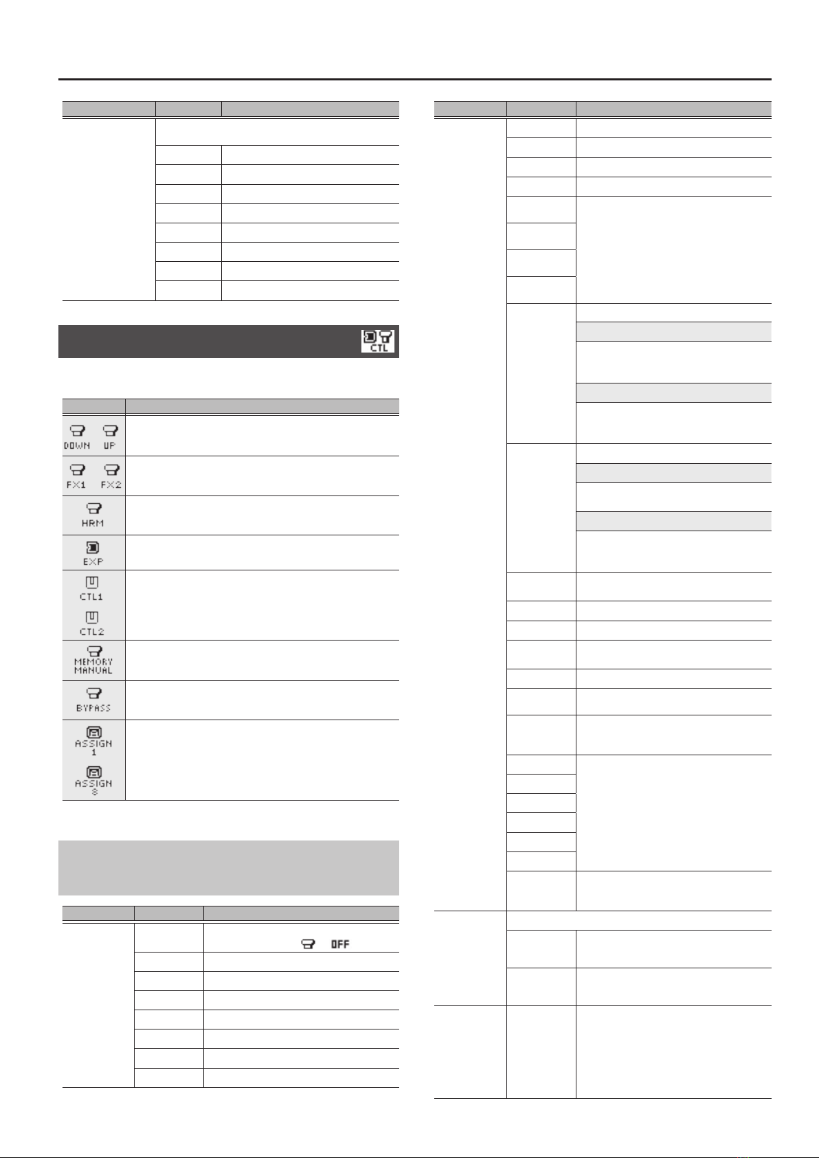
CTL&ASSIGN SETTING . . . . . . . . . . . . . . . . . . . . . . . . . . . . . . . . . 17
Common to
DOWN, UP, FX1, FX2, HRM, CTL1, CTL2,
MEM/MAN, BYPASS . . . . . . . . . . . . . . . . . . . . . . . . . . . . . . . . . . . . 17
EXP . . . . . . . . . . . . . . . . . . . . . . . . . . . . . . . . . . . . . . . . . . . . . 18
ASSIGN 1–8 . . . . . . . . . . . . . . . . . . . . . . . . . . . . . . . . . . . . . . 18
ASSIGN COMMON. . . . . . . . . . . . . . . . . . . . . . . . . . . . . . . . 19
Virtual Expression Pedal System (Internal Pedal/
Wave Pedal) . . . . . . . . . . . . . . . . . . . . . . . . . . . . . . . . . . . . . 23
MENU. . . . . . . . . . . . . . . . . . . . . . . . . . . . . . . . . . . . . . . . . . . . . . . . . . . . 24
DISPLAY . . . . . . . . . . . . . . . . . . . . . . . . . . . . . . . . . . . . . . . . . . . . . . 24
INPUT . . . . . . . . . . . . . . . . . . . . . . . . . . . . . . . . . . . . . . . . . . . . . . . . 24
OUTPUT . . . . . . . . . . . . . . . . . . . . . . . . . . . . . . . . . . . . . . . . . . . . . . 24
PLAY (PLAY OPTION) . . . . . . . . . . . . . . . . . . . . . . . . . . . . . . . . . . . 25
KNOB (KNOB SETTING) . . . . . . . . . . . . . . . . . . . . . . . . . . . . . . . . 25
PREF (PREFERENCE). . . . . . . . . . . . . . . . . . . . . . . . . . . . . . . . . . . . 28
TUNER . . . . . . . . . . . . . . . . . . . . . . . . . . . . . . . . . . . . . . . . . . . . . . . . 29
MIDI . . . . . . . . . . . . . . . . . . . . . . . . . . . . . . . . . . . . . . . . . . . . . . . . . . 29
USB. . . . . . . . . . . . . . . . . . . . . . . . . . . . . . . . . . . . . . . . . . . . . . . . . . . 30
AUTO OFF. . . . . . . . . . . . . . . . . . . . . . . . . . . . . . . . . . . . . . . . . . . . . 30
F.RESET (FACTORY RESET) . . . . . . . . . . . . . . . . . . . . . . . . . . . . . . 30

3
Basic Operation
Basic Procedure for Eect Editing
1. Recall the patch that you want to edit.
5Switch to memory mode.
5Use the [?] [=] switches to select a patch.
Patch down Patch up
You can turn knob [1] to select patches consecutively.
2. Press the [EFFECT EDIT] button.
The eect select screen appears.
3. Use knob [1] to select the eect that you want to
edit.
You can use the [EFFECT EDIT] ([ON/OFF]) button or knob [2] to
turn on/o the eect where the cursor is located (highlighted).
An eect that is on is shown by an icon. An eect that is o is
shown as “OFF.”
MEMO
For FX1-4, and HRM (VOC), you can use knob [3] to choose the
eect type.
4. Press the [ENTER] button to access the edit screen.
MEMO
In the edit screen, press the [ON/OFF] button to turn the eect on/
o. This lets you hear what the eect does. In screens where page
tabs are displayed, use the [< PAGE] [PAGE >] buttons to move
between editing screen pages.
5. Use knobs [1]–[3] to specify the value of each
parameter shown in the screen.
6. Press the [EXIT] button a number of times to return
to the play screen.
Changing the Eect Connections
1. In the eect select screen, choose“MST.”
2. Use “FX STRUCTURE” to change the order in which
FX1–4 are connected.
3. Use “REVERB STRUCTURE” to change the order in
which REV1 and REV2 are connected.
The eect connection changes.
Changing the CTL & ASSIGN Settings
You can operate a variety of parameters by making CTL and ASSIGN
settings for each patch.
1. In the eect select screen, use knob [1] to select
“CTL,” and then press the [ENTER] button.
The CTL & ASSIGN screen appears.
2. Use knobs [1]–[3] to select the controller that you
want to edit.
An icon indicates controllers that are turned on. Controllers that
are o are indicated by “OFF.”
3. Press the [ENTER] button to move to the edit
screen.
In screens where page tabs are displayed, use the [< PAGE]
[PAGE >] buttons to switch between edit screen pages.
4. Use knobs [1]–[3] to edit the parameter values in
the screen.
5. Press the [EXIT] button a number of times to return
to the play screen.
4
Basic Operation
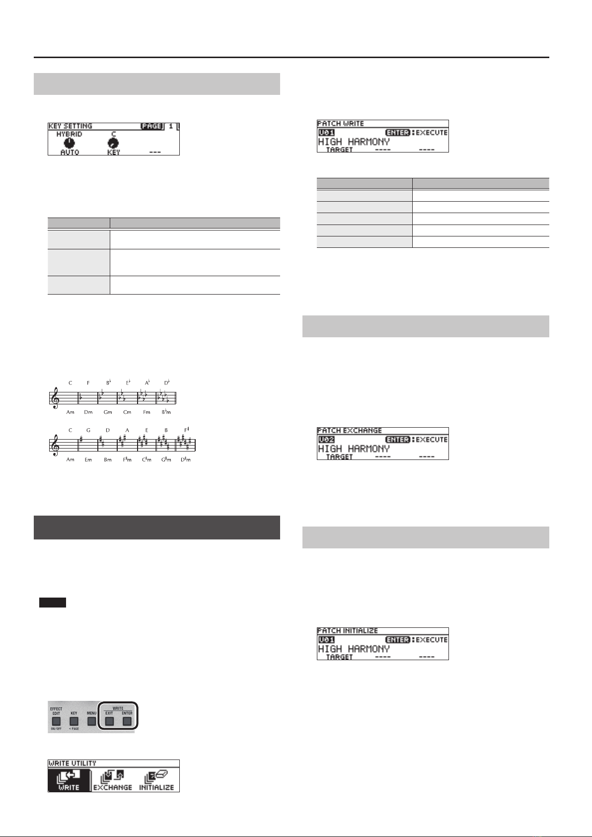
Matching the Harmony to the Key of the Song
1. Press the [KEY] button.
2. Use knob [1] to specify the “AUTO” setting.
If Auto is set to“FULL” or “HYBRID,” the key is specied automatically
according to the chords and the chord progression that you play on the
connected guitar.
AUTO Explanation
FULL Harmony is added according to the chords and the
chord progression that you play on your guitar.
HYBRID Harmony is added according to the“KEY” setting and the
chords that you play on your guitar.
OFF Harmony is added according to the “KEY” setting.
* Try the FULL setting, and if you don’t get the harmony that you
expect, use the HYBRID setting. If you’re not using a guitar, turn
this OFF and specify the key.
3. Use knob [2] to specify the “KEY.”
* As shown in the illustration below, specify the key of the song
that you’re singing.
4. Press the [EXIT] button a number of times to return
to the play screen.
Saving a Patch (Write)
If you want to save the patch that you created, execute the Write
operation.
* You can use dedicated software to save, exchange, initialize, or
back up patches.
NOTE
5If you do not save the patch, the edited settings will be lost when
you turn o the power or switch to another patch.
5When you save, the patch that had been in the save-destination is
overwritten.
1. Press the [EXIT] button and [ENTER] button
simultaneously.
The WRITE UTILITY screen appears.
2. Select “WRITE” and then press the [ENTER] button.
3. Choose the patch write destination (U01–U99) with
the [1] knob, and press the [ENTER] button.
Here you can edit the name.
Controller Operation
[1] knob Changes the character
[2] knob Moves the cursor
[3] knob Selects the type of characters
[EFFECT EDIT] button Delete the character at the cursor location
[MENU] button Insert a space at the cursor location
4. To save the patch, press the [ENTER] button.
* If you decide to cancel, press the [EXIT] button.
Once the patch has been saved, you are returned to the Play
screen.
Exchanging Patches
Here’s how to exchange the currently selected patch with a patch
that you specify.
1. In the WRITE UTILITY screen, select “EXCHANGE”
and press the [ENTER] button.
2. Choose the exchange-destination patch with the
[1] knob.
3. To exchange the patches, press the [ENTER] button.
* If you decide to cancel, press the [EXIT] button.
Once the patches has been exchanged, you are returned to the
Play screen.
Initializing a Patch
Here’s how to return the selected patch to the default values.
1. In the WRITE UTILITY screen, select “INITIALIZE” and
press the [ENTER] button.
2. Choose the initialize-destination patch with the [1]
knob.
3. To initialize the patch, press the [ENTER] button.
* If you decide to cancel, press the [EXIT] button.
Once the patch has been initialized, you are returned to the Play
screen.
5
EFFECT
ENHANCE
ENHANCE is an eect that makes the sound more sharply dened.
It also contains COMPRESSOR which makes the volume more
consistent, DE-ESSER which suppresses sibilance, and EQ which
adjusts the tonal character.
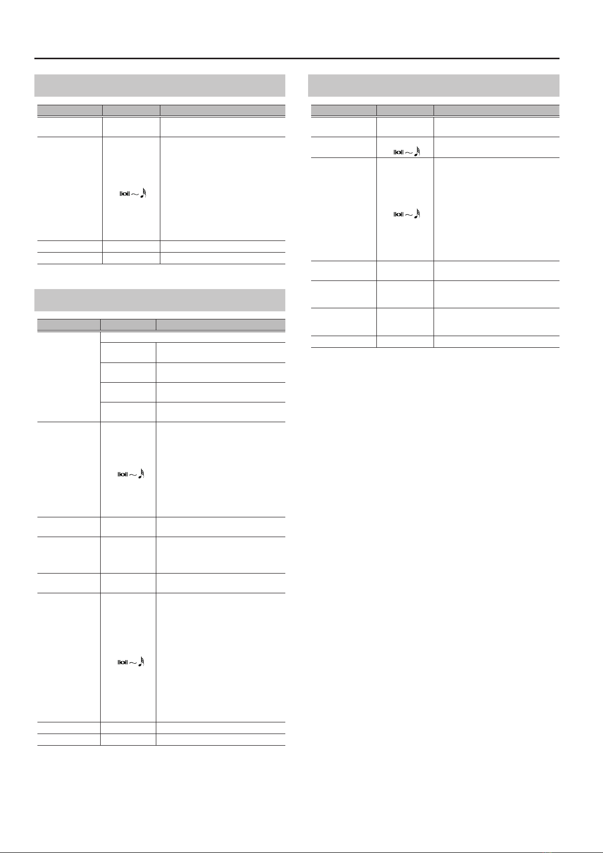
Parameter Value Explanation
ON/OFF OFF, ON Turns this eect on/o.
ENHANCE 0–100
Adjusts the depth of ENHANCE. The
sound becomes more sharply dened as
this value is increased.
COMPRESS 0–100
Adjusts the depth of COMPRESSOR. The
volume becomes more consistent as this
value is increased.
DE-ESSER 0–100
Adjusts the depth of DE-ESSER. Sibilance
is suppressed more strongly as this value
is increased.
LOW GAIN -20–+20dB Adjusts the low frequency range tone.
HIGH GAIN -20–+20dB Adjusts the high frequency range tone.
LEVEL -20–+20dB Adjusts the overall volume level of the
equalizer.
LMID GAIN
(LOW-MID GAIN) -20–+20dB Adjusts the low-middle frequency range
tone.
LMID FREQ
(LOW-MID
FREQUENCY)
20–16.0kHz
Species the center of the frequency
range that will be adjusted by the LMID
GAIN.
LMID Q
(LOW-MID Q) 0.5–16
Adjusts the width of the area aected
by the EQ centered at the LMID FREQ.
Higher values will narrow the area.
HMID GAIN
(LOW-MID GAIN) -20–+20dB Adjusts the high-middle frequency
range tone.
HMID FREQ
(HIGH-MID
FREQUENCY)
20–16.0kHz
Species the center of the frequency
range that will be adjusted by the HMID
GAIN.
HMID Q
(HIGH-MID Q) 0.5–16
Adjusts the width of the area aected
by the EQ centered at the HMID FREQ.
Higher values will narrow the area.
LOW CUT FLAT, 20–800Hz
This sets the frequency at which the low
cut lter begins to take eect. When
“FLAT” is selected, the low cut lter will
have no eect.
HIGH CUT 630Hz–16.0kHz,
FLAT
This sets the frequency at which the
high cut lter begins to take eect.
When “FLAT” is selected, the high cut
lter will have no eect.
PITCH CORRECT
PITCH CORRECT suppresses instabilities in pitch. You can also convert
pitch changes to a stair-step form, producing a mechanical eect.
Parameter Value Explanation
ON/OFF OFF, ON Turns this eect on/o.
TYPE
SOFT The pitch will be corrected smoothly.
HARD The pitch will be corrected quickly.
ELECTRIC Corrects pitch variation to a stair-step
change.
ROBOT Corrects the pitch to the specied note
(Robot Voice).
SCALE
CHROMATIC The pitch is corrected to the nearest
chromatic semitone.
KEY The pitch is corrected according to the
Key setting (p. 4).
NOTE C–B Species the pitch (xed) when Type is
set to “Robot.”
FORMANT -50–+50
Negative (–) settings give the voice a
more masculine character, while positive
(+) settings make the voice more
feminine.
SHIFT
Species the amount by which the pitch is shifted.
-12–+12 The pitch is shifted by the specied
interval.
USER-INT1–4
The pitch is shifted by the interval
specied by USR-INTERVAL (HARMONY
parameter).
SPEED 0–10 Adjusts the speed of pitch change.
Higher values produce faster change.
STABILITY -10–+10 Adjusts the ease of pitch change. Higher
values make change more dicult.
M>PCR
(MIDI TO PITCH)
The received MIDI note message is used to correct the pitch.
If no message is being received, the SHIFT setting is used.
Ch.1–16 Note messages of the specied MIDI
channel are used for correction.
RX
Note messages on the MIDI channel
specied by the SYSTEM MIDI setting RX
CH are used for correction.
OFF O
ZONE LO
(ZONE LOWER)
C1–G9 Species the range in which note
messages are accepted.
ZONE UP
(ZONE UPPER)
C1–G9

6
EFFECT
HARMONY/VOCODER
HARMONY can add natural harmony to your voice. VOCODER applies
the character of a human voice to a synth sound, producing a
distinctive vocoder sound (robot voice).
You can apply either the HARMONY or the VOCODER eect. These
eects are called LFX (LEAD FX).
Parameter Explanation
TYPE Refer to LFX TYPE (LEAD FX TYPE)
How to choose LFXTYPE
1. Press the [EFFECT EDIT] button.
2. Choose “HRM” with the [1] knob.
3. Choose “TYPE”with the [3] knob.
LFX TYPE (LEAD FX TYPE)
This is a list of the eects that can be selected for HARMONY/
VOCODER.
TYPE Explanation
HARMONY Applies a harmony eect.
VOCODER Applies a vocoder eect.
HARMONY
Parameter Value Explanation
COMN (COMMON)
ON/OFF OFF, ON Turns this eect on/o.
E.LEVEL 0–100 Adjusts the overall volume level of the
harmony.
D.LEVEL 0–100 Adjusts the volume of the sound of the
mic.
NOTE SENS LOW, MID, HIGH
Species the upper limit frequency at
which the harmony eect is applied.
* In an environment in which acoustic
feedback is prone to occur, using the
“LOW” setting can suppress unwanted
sound.
HRM1–3 (HARMONY1–3)
VOICE
(AUTO)
OFF Turns the harmony part o.
UNISON
This produces the impression that
another person is singing the same
melody along with you.
OCT- Adds sound an octave lower.
LOWER Adds lower sound based on 6th or 5th.
*1
LOW Adds lower sound based on 4th or 3rd.
*1
HIGH Adds higher sound based on 4th or
3rd. *1
HIGHER Adds higher sound based on 6th or
5th. *1
OCT+ Adds sound an octave higher.
USR-INT1–4
Adds sound as specied by the USER
INTERVAL 1–4 setting. You can directly
specify the pitch of the harmony. *2
Parameter Value Explanation
VOICE
(MANUAL)
OFF Turns the harmony part o.
UNISON
This produces the impression that
another person is singing the same
melody along with you.
OCT- Adds sound an octave lower.
-6TH, -5TH, -4TH,
-3RD, +3RD, +4TH,
+5TH, +6TH
Adds harmony at the specied pitch
interval of the diatonic scale.
OCT+ Adds sound an octave higher.
USR-INT1–4
Adds sound as specied by the USER
INTERVAL 1–4 setting. You can directly
specify the pitch of the harmony. *2
PAN L100–CENTER
–R100
Adjusts the panning of the harmony
part.
LEVEL 0–100 Adjusts the volume of the harmony part.
DELAY 0–10 Adjusts the delay of the harmony part.
ACCURACY 0–10
Raising this value makes the pitch of the
harmony more closely match the pitch
of the original vocal.
* With the higher value, the harmony
is sounded at the precise pitch; this
means that if the pitch of the original
vocal is not precise, the result might
not sound harmonious. In such cases,
try decreasing this value.
VIBRATO -10–+10
Species how closely the vibrato will
follow.
* If you want to decrease the
expressiveness of the harmony relative
to your own voice, use a setting in the
negative range.
METHOD SCALE1–2,
CHORD1–2
Species the rule by which the pitch of
the harmony is determined. This setting
species whether the harmony is biased
toward the scale (KEY) or the chord.
FORMANT -50–+50 Adjusts the vocal character of the
harmony part.
TONE -50–+50 Adjusts the tonal character of the
harmony part.
DOUBLE
(DOUBLE DEPTH)
Double-tracking is a popular recording studio technique
in which a vocalist records a melody, then overdubs a
second performance of the same melody along with the
rst recording. When the two performances are played back
together, it gives the eect of a thick and rich single voice.
OFF
Adjusts the intensity of the Double
eect in three levels (Light/Normal/
Deep).
LIGHT
NORMAL
DEEP
M>VOICE
(MIDI TO VOICE)
Adds harmony at the pitch specied by an incoming MIDI
note message. If a note message is not received, the VOICE
setting is used.
Ch.1–16 Applies correction according to note
messages of the specied MIDI channel.
RX
Applies correction according to note
messages of the MIDI channel specied
by the SYSTEM MIDI setting RX CH.
OFF O
ZONE LO
(ZONE LOWER)
C1–G9
Species the range in which note
messages are accepted.
ZONE UP
(ZONE UPPER)
C1–G9

7
EFFECT
Parameter Value Explanation
INTERVAL1–4 (USER INTERVAL1–4)
C
-12 (C) –0 (C) –+12 (C)
Adds harmony to the pitch detected
at the MIC input at the interval directly
specied by this setting.
D
-12 (D )–0 (D )–+12 (D )
D
-12 (D) –0 (D) –+12 (D)
E
-12 (E )–0 (E )–+12 (E )
E
-12 (E) –0 (E) –+12 (E)
F
-12 (F) –0 (F) –+12 (F)
F#
-12 (F#)–0 (F#)–+12 (F#)
G
-12 (G) –0 (G) –+12 (G)
A
-12 (A )–0 (A )–+12 (A )
A
-12 (A) –0 (A) –+12 (A)
B
-12 (B )–0 (B )–+12 (B )
B
-12 (B) –0 (B) –+12 (B)
*1 Depending on conditions, other intervals are also added.
*2 If you select USR-INT, chord detection from MIDI and INST are disabled.
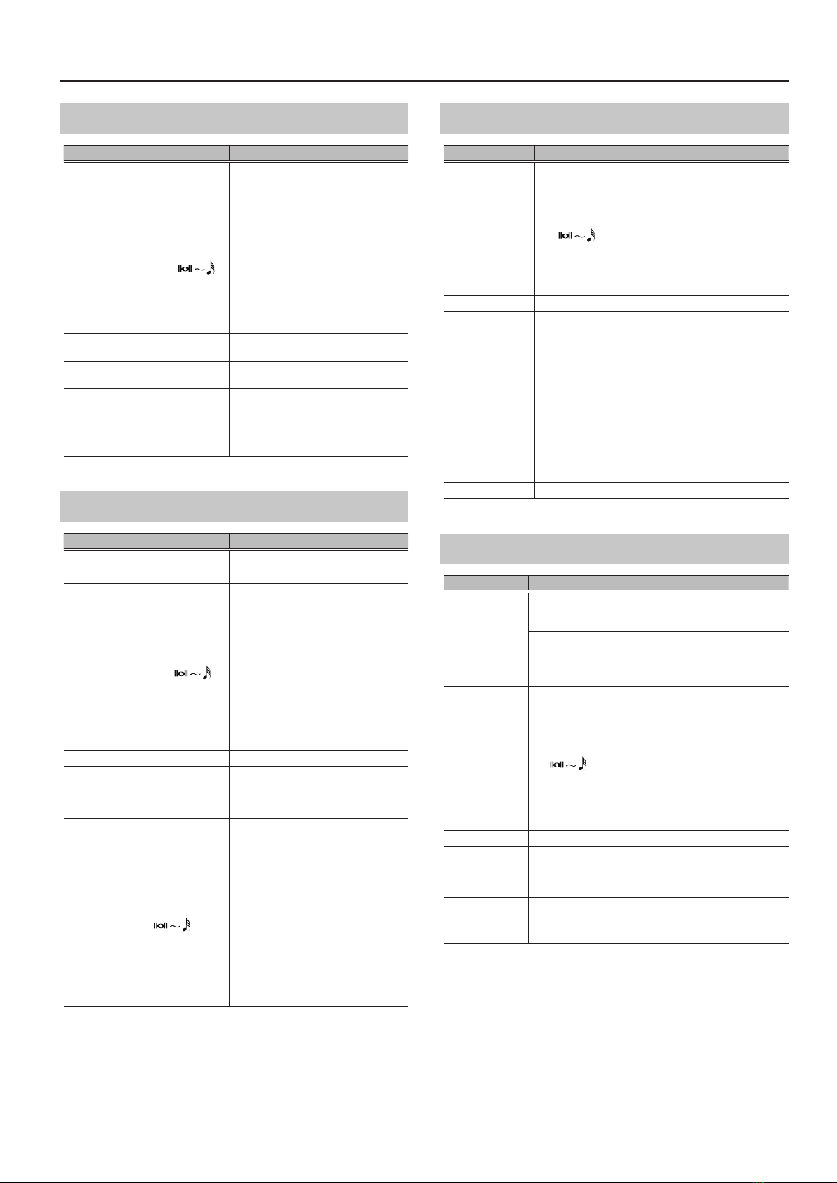
VOCODER
Parameter Value Explanation
COMN (COMMON)
ON/OFF OFF, ON Turns this eect on/o.
E.LEVEL 0–100 Adjusts the overall volume level of the
vocoder.
D.LEVEL 0–100 Adjusts the volume of the sound of the
mic.
VOC (VOCODER)
SOURCE
Selects how VOCODER is used.
INST
VOCODER is sounded using an
instrument connected to the INST INPUT
jack.
MIDI
VOCODER is sounded according to
note messages received at the MIDI IN
connector.
MIDI (USB) VOCODER is sounded according to note
messages received at the USB port.
MIC Vocoder sound is produced when you
simply sing.
AUTO Species the input source in the priority
order of INST>MIDI>MIC.
TYPE
Switches the vocoder type.
STANDARD Vocoder sound with high clarity,
producing a natural vocal character.
VINTAGE Vocoder sound often used in techno of
the ’80s.
TALK BOX Sound reminiscent of a talk box.
LEVEL 0–100 Adjusts the volume of the vocoder.
CARRIER
(INST)
SAW,
VINTAGE SAW,
DETUNE SAW,
SQUARE,
RECTANGLE,
DISTORTION
Selects the carrier waveform (the basic
sound).
* This can be specied if SOURCE is
“INST.”
CARRIER
(MIDI, MIC)
SAW,
VINTAGE SAW,
DETUNE SAW,
SUPER SAW
SQUARE,
RECTANGLE
Selects the carrier waveform (the basic
sound).
* This can be specied if SOURCE is
other than “INST.”
OCTAVE -2OCT, -1OCT, 0,
+1OCT
Species the pitch of the sound.
* This can be specied if CARRIER is
other than “DISTORTION.”
Parameter Value Explanation
DRIVE 0–100
Adjusts the amount of distortion for the
eect sound.
* This can be specied if CARRIER is
“DISTORTION.”
FORMANT -50–+50 Adjusts the vocal character of the
vocoder part.
TONE -50–+50 Adjusts the tonal character of the
vocoder part.
ATTACK 0–100
Species the rise time (attack time) for
sound initiated by a note message.
* This can be specied if SOURCE is
“MIDI” or “MIDI (USB).”
RELEASE 0–100
Species the decay time (release time)
for sound initiated by a note message.
* This can be specied if SOURCE is
“MIDI” or “MIDI (USB).”
BEND 0–12
Species the degree of pitch change in
semitones when the Pitch Bend lever is
all the way right (left).
For example if this is set to “12” and you
move the pitch bend lever all the way
to the right (left), the pitch will rise (fall)
1 octaves.
* This can be specied if SOURCE is
“MIDI” or “MIDI (USB).”
VEL SENS
0–100
Species the sensitivity to the keyboard
dynamics (velocity) of the note message.
* This can be specied if SOURCE is
“MIDI” or “MIDI (USB).”
CHROMATIC
OFF, ON
The pitch varies in stairstep fashion by
semitone steps.
* This can be specied if SOURCE is
“MIC.”
8
EFFECT
FX1-4
With FX1-4, you can select the eect to be used from the following.
You can select the same eect for FX1-4.
Parameter Value Explanation
ON/OFF OFF, ON Turns this eect on/o.
TYPE Refer to FX1-4 TYPE
How to chooseTYPE
1. Press the [EFFECT EDIT] button.
2. Choose “FX1-4” with the [1] knob.
3. Choose “TYPE”with the [3] knob.
FX1-4 TYPE
This is a list of the eects that can be selected for FX1-4.
Eect name Explanation
DISTORTION Produces a distorted voice.
RADIO Produces a radio voice.
LO-FI This eect intentionally degrades the sound to create a
distinctive character.
FILTER A lter modies the brightness or thickness of the sound
by cutting a specic frequency range.
T.WAH You can produce a wah eect with the lter changing in
response to level.
RING MODULATOR
Gives a metallic character to the sound, creating the
impression that the sound is going out of focus.
CHORUS In this eect, a slightly detuned sound is added to the
original sound to add depth and breadth.
FLANGER The anging eect gives a twisting, jet-airplane-like
character to the sound.
TREMOLO Tremolo is an eect that creates a cyclic change in volume.
PHASER
By adding varied-phase portions to the direct sound, the
phaser eect gives a whooshing, swirling character to the
sound.
ROTARY This produces an eect like the sound of a rotary speaker.
SLICER This consecutively interrupts the sound to create the
impression that a rhythm backing phrase is being played.
ISOLATOR
Divides the audio input into three ranges (LO, MID, HI) and
cuts the specied region. You can cut in synchronization
with the tempo.
VIBRATO This eect creates vibrato by slightly modulating the pitch.
PAN Moves the stereo position (pan).
ROLL This loops the input sound at a short interval, and divides
that length.
FREEZE This produces the Freeze function to hold sounds.
GRANULAR DELAY Repeats a short portion of the input sound, giving it a
buzzy character or producing the eect of playing a roll.
DELAY This eect adds delayed sound to the direct sound, giving
more body to the sound or creating special eects.
REVERB This eect adds reverberation (reverb) to the direct sound,
adding acoustical depth to the sound.
DISTORTION
Parameter Value Explanation
DIST 0–100 Adjusts the degree of distortion.
TONE -50–+50 Adjusts the tonal character.
E.LEVEL 0–100 Adjusts the volume of the eect sound.
D.LEVEL 0–100 Adjusts the volume of the direct sound.
RADIO
Parameter Value Explanation
LO-FI 1–10 Adjusts the amount of blurring.
LEVEL 0–100 Adjusts the volume of the eect sound.
LO-FI
Parameter Value Explanation
BIT 32–1BIT Species the bit depth.
SAMPLE 1/1–1/32 Species the sampling rate.
BALANCE 0–100 Adjusts the volume balance between the
direct sound and the eect sound.
FILTER
Parameter Value Explanation
TYPE
Selects the type of lter.
LPF This reduces the volume of all frequencies
above the cuto frequency.
BPF
This leaves only the frequencies in the
region of the cuto frequency, and cuts
the rest.
HPF This cuts the frequencies in the region
below the cuto frequency.
RATE 0–100, BPM Adjusts the rate of modulation.
LEVEL 0–100 Adjusts the volume of the eect sound.
DEPTH 0–100 Adjusts the depth of modulation.
RESONANCE 0–100 Adjusts the intensity of the eect.
CUTOFF 0–100 Adjusts the cuto frequency of the lter.
STEP RATE OFF, 0–100, BPM
Adjusts the frequency of the step
function that varies the modulation
in stairstep fashion. When it is set to a
higher value, the change will be ner.
Set this to “OFF”when not using the Step
function.
* When set to BPM, the value of each
parameter will be set according to
the value of the “MASTER BPM”(p. 16)
specied for each patch. This makes it
easier to achieve eect sound settings
that match the tempo of the song.
* If, due to the tempo, the time is longer
than the range of allowable settings, it
is then synchronized to a period either
1/2 or 1/4 of that time.
MODE
Selects the mode of lter.
AUTO The CUTOFF changes at the rate specied
by RATE.
MANUAL The eect is applied with a xed CUTOFF.
9
EFFECT
T.WAH
Parameter Value Explanation
TYPE
Selects the wah mode.
LPF Low pass lter. This creates a wah eect over a
wide frequency range.
BPF Band pass lter. This creates a wah eect in a
narrow frequency range.
POLARITY
Selects the direction in which the lter will change in
response to the input.
DOWN The frequency of the lter will fall.
UP The frequency of the lter will rise.
SENS 0–100
Adjusts the sensitivity at which the lter will
change in the direction determined by the
polarity setting.
Higher values will result in a stronger response.
FREQ 0–100 Adjusts the center frequency of the Wah eect.
PEAK 0–100
Adjusts the way in which the wah eect applies
to the area around the center frequency.
Higher values will produce a stronger tone
which emphasizes the wah eect more. With
a value of 50 a standard wah sound will be
produced.
E.LEVEL 0–100 Adjusts the volume of the eect sound.
D.LEVEL 0–100 Adjusts the volume of the direct sound.
RING MODULATOR
Parameter Value Explanation
FREQ 0–100 Adjusts the frequency of the internal
oscillator.
E.LEVEL 0–100 Adjusts the volume of the eect sound.
D.LEVEL 0–100 Adjusts the volume of the direct sound.
CHORUS
Parameter Value Explanation
TYPE
Selects the chorus type.
MONO
This chorus eect outputs the same
sound from both L channel and R
channel.
STEREO
This is a stereo chorus eect that adds
dierent chorus sounds to L channel
and R channel.
RATE 0–100,
BPM
Adjust the speed of the chorus eect
for the high frequency range.
* When set to BPM, the value of each
parameter will be set according to
the value of the “MASTER BPM”(p.
16) specied for each patch. This
makes it easier to achieve eect
sound settings that match the
tempo of the song.
* If, due to the tempo, the time is
longer than the range of allowable
settings, it is then synchronized to a
period either 1/2 or 1/4 of that time.
DEPTH 0–100
Adjusts the depth of the chorus eect.
* To use it for doubling eect, set the
value to 0.
E.LEVEL 0–100 Adjusts the volume of the eect
sound.
PRE-DELAY 0.0–60.0ms
Adjusts the time needed for the eect
sound to be output after the direct
sound has been output.
By setting a longer pre delay time, you
can obtain an eect that sounds like
more than one sound is being played
at the same time (doubling eect).
Parameter Value Explanation
LOW CUT FLAT,
20–800Hz
This sets the frequency at which the
low cut lter begins to take eect.
When FLAT is selected, the low cut
lter will have no eect.
HIGH CUT 630Hz–
12.5kHz, FLAT
This sets the frequency at which the
high cut lter begins to take eect.
When FLAT is selected, the high cut
lter will have no eect.
D.LEVEL 0–100 Adjusts the volume of the direct
sound.
FLANGER
Parameter Value Explanation
RATE 0–100,
BPM
Adjusts the rate of the anging eect.
* When set to BPM, the value of each
parameter will be set according to
the value of the “MASTER BPM”(p. 16)
specied for each patch. This makes it
easier to achieve eect sound settings
that match the tempo of the song.
* If, due to the tempo, the time is longer
than the range of allowable settings, it
is then synchronized to a period either
1/2 or 1/4 of that time.
DEPTH 0–100 Determines the depth of the anging
eect.
RESONANCE 0–100
Determines the amount of resonance
(feedback). Increasing the value will
emphasize the eect, creating a more
unusual sound.
MANUAL 0–100 Adjusts the center frequency at which to
apply the eect.
SEPARATION 0–100 Adjusts the diusion. The diusion
increases as the value increases.
LOW CUT FLAT,
55–800Hz
Adjusts the frequency at which the low
cut lter begins to take eect. When
“FLAT” is selected, the low cut lter will
have no eect.
E.LEVEL 0–100 Adjusts the volume of the anger.
D.LEVEL 0–100 Adjusts the volume of the direct sound.
STEP RATE OFF, 0–100,
BPM
Adjusts the frequency of the step
function that varies the modulation
in stairstep fashion. When it is set to a
higher value, the change will be ner.
Set this to “OFF”when not using the
Step function.
* When set to BPM, the value of each
parameter will be set according to
the value of the “MASTER BPM”(p. 16)
specied for each patch. This makes it
easier to achieve eect sound settings
that match the tempo of the song.
* If, due to the tempo, the time is longer
than the range of allowable settings, it
is then synchronized to a period either
1/2 or 1/4 of that time.
10
EFFECT
TREMOLO
Parameter Value Explanation
WAVE
(WAVE SHAPE) 0–100 Adjusts changes in volume level. A
higher value will steepen wave’s shape.
RATE 0–100,
BPM
Adjusts the frequency (speed) of the
change.
* When set to BPM, the value of each
parameter will be set according to
the value of the “MASTER BPM”(p. 16)
specied for each patch. This makes it
easier to achieve eect sound settings
that match the tempo of the song.
* If, due to the tempo, the time is longer
than the range of allowable settings, it
is then synchronized to a period either
1/2 or 1/4 of that time.
DEPTH 0–100 Adjusts the depth of the eect.
LEVEL 0–100 Adjusts the volume.
PHASER
Parameter Value Explanation
TYPE
Selects the number of stages that the phaser eect will use.
4STAGE This is a four-phase eect. A light phaser
eect is obtained.
8STAGE This is a eight-phase eect. It is a popular
phaser eect.
12STAGE This is a twelve-phase eect. A deep
phase eect is obtained.
BiPHASE This is the phaser with two phase shift
circuits connected in series.
RATE 0–100,
BPM
Adjust the rate of the phaser eect.
* When set to BPM, the value of each
parameter will be set according to
the value of the “MASTER BPM”(p. 16)
specied for each patch. This makes it
easier to achieve eect sound settings
that match the tempo of the song.
* If, due to the tempo, the time is longer
than the range of allowable settings, it
is then synchronized to a period either
1/2 or 1/4 of that time.
DEPTH 0–100 Determines the depth of the phaser
eect.
RESONANCE 0–100
Determines the amount of resonance
(feedback). Increasing the value will
emphasize the eect, creating a more
unusual sound.
MANUAL 0–100 Adjusts the center frequency of the
phaser eect.
STEP RATE OFF, 0–100,
BPM
Adjusts the cycle of the step function that
changes the rate and depth. When it is set
to a higher value, the change will be ner.
Set this to “OFF”when not using the Step
function.
* When set to BPM, the value of each
parameter will be set according to
the value of the “MASTER BPM”(p. 16)
specied for each patch. This makes it
easier to achieve eect sound settings
that match the tempo of the song.
* If, due to the tempo, the time is longer
than the range of allowable settings, it
is then synchronized to a period either
1/2 or 1/4 of that time.
E.LEVEL 0–100 Adjusts the volume of the phaser.
D.LEVEL 0–100 Adjusts the volume of the direct sound.
ROTARY
Parameter Value Explanation
SPEED SLOW, FAST Changes the simulated speaker’s
rotating speed (SLOW or FAST).
RATE SLOW 0–100,
BPM
Adjusts the SPEED of rotation when set
to “SLOW.”
RATE FAST 0–100,
BPM
Adjusts the SPEED of rotation when set
to “FAST.”
* When set to BPM, the value of each
parameter will be set according to
the value of the “MASTER BPM”(p. 16)
specied for each patch. This makes it
easier to achieve eect sound settings
that match the tempo of the song.
* If, due to the tempo, the time is longer
than the range of allowable settings, it
is then synchronized to a period either
1/2 or 1/4 of that time.
DEPTH 0–100 Adjusts the amount of depth in the
rotary eect.
RISE TIME 0–100
Adjusts the time it takes for the rotation
SPEED to change when switched from
“SLOW” to “FAST.”
FALL TIME 0–100
Adjusts the time it takes for the rotation
SPEED to change when switched from
“FAST” to “SLOW.”
E.LEVEL 0–100 Adjusts the volume of the eect sound.
11
EFFECT
SLICER
Parameter Value Explanation
PATTERN P01–P20 Selects the slice pattern that will be used
to cut the sound.
RATE 0–100,
BPM
Adjust the rate at which the sound will
be cut.
* When set to BPM, the value of each
parameter will be set according to
the value of the “MASTER BPM”(p. 16)
specied for each patch. This makes it
easier to achieve eect sound settings
that match the tempo of the song.
* If, due to the tempo, the time is longer
than the range of allowable settings, it
is then synchronized to a period either
1/2 or 1/4 of that time.
DUTY 1–99 Adjusts the length of the sound for the
slice pattern.
DEPTH 0–100 Adjusts the depth to which the slice
pattern is applied.
ATTACK 0–100 Adjusts the attack volume of the slice
pattern.
TRIGGER OFF, ON
Resets the slicer pattern to its beginning.
* It is assumed that this parameter will be
assigned to the footswitch (p. 17).
ISOLATOR
Parameter Value Explanation
BAND LOW, MID, HIGH Select the range that will be cut.
RATE 0–100,
BPM
Adjusts the frequency that is cut. This lets
you cut the low- or high-frequency range
at intervals of the specied note value in
synchronization with the tempo.
* When set to BPM, the value of each
parameter will be set according to
the value of the “MASTER BPM”(p. 16)
specied for each patch. This makes it
easier to achieve eect sound settings
that match the tempo of the song.
* If, due to the tempo, the time is longer
than the range of allowable settings, it
is then synchronized to a period either
1/2 or 1/4 of that time.
DEPTH 0–100 Adjusts the depth of modulation.
BAND LEVEL 0–100
Adjusts the reference volume of the band
that is cut.
The portion between BAND LEVEL and
DEPTH is cut at the rate specied by RATE.
STEP RATE
OFF,
0–100, BPM
Adjusts the rate of the step function that
produces stairstep change in the amount
that is cut. When it is set to a higher value,
the change will be ner.
Set this to “OFF”when not using the Step
function.
* When set to BPM, the value of each
parameter will be set according to
the value of the “MASTER BPM”(p. 16)
specied for each patch. This makes it
easier to achieve eect sound settings
that match the tempo of the song.
* If, due to the tempo, the time is longer
than the range of allowable settings, it
is then synchronized to a period either
1/2 or 1/4 of that time.
VIBRATO
Parameter Value Explanation
RATE 0–100,
BPM
Adjusts the rate of the vibrato.
* When set to BPM, the value of each
parameter will be set according to
the value of the “MASTER BPM”(p. 16)
specied for each patch. This makes it
easier to achieve eect sound settings
that match the tempo of the song.
* If, due to the tempo, the time is longer
than the range of allowable settings, it
is then synchronized to a period either
1/2 or 1/4 of that time.
DEPTH 0–100 Adjusts the depth of the vibrato.
TRIGGER OFF, ON
Selects on/o of the vibrato.
* It is assumed that this parameter will
be assigned to the footswitch (p. 17).
RISE TIME 0–100
Adjusts the time passing from the
moment the TRIGGER is turned on until
the set vibrato is obtained.
* When a patch with TRIGGER set to
ON is called up, the eect obtained
is identical to what happens when
TRIGGER is switched from O to
On. If you want the vibrato eect to
be produced immediately after the
patches are switched, set RISE TIME
to 0.
LEVEL 0–100 Adjusts the volume.
PAN
Parameter Value Explanation
TYPE
AUTO
This varies the volume level on the left
and right according to the settings for
WAVE, RATE, and DEPTH.
MANUAL Output uses the volume balance set
with POS.
WAVE
(WAVE SHAPE) *1 0–100 Adjusts changes in volume level. A
higher value will steepen wave’s shape.
RATE *1 0–100,
BPM
Adjusts the frequency (speed) of the
change.
* When set to BPM, the value of each
parameter will be set according to
the value of the “MASTER BPM”(p. 16)
specied for each patch. This makes it
easier to achieve eect sound settings
that match the tempo of the song.
* If, due to the tempo, the time is longer
than the range of allowable settings, it
is then synchronized to a period either
1/2 or 1/4 of that time.
DEPTH *1 0–100 Adjusts the depth of the eect.
INIT PHASE *1 0, 15, 30–345
Adjusts the PAN position.
Species the rotational angle of the
phase from the default (when the eect
is turned on) of 0 (center).
POSITION *2 L100–CENTER
–R100
This adjusts the volume balance
between L channel and R channel.
LEVEL 0–100 Adjusts the volume.
*1 Setting available when TYPE is set to AUTO.
*2 Setting available when TYPE is set to MANUAL.
12
EFFECT
ROLL
Parameter Value Explanation
TIME 1–1000ms,
BPM
Species the loop rate.
* When set to BPM, the value of each
parameter will be set according to
the value of the “MASTER BPM”(p. 16)
specied for each patch. This makes it
easier to achieve eect sound settings
that match the tempo of the song.
* If, due to the tempo, the time is longer
than the range of allowable settings, it
is then synchronized to a period either
1/2 or 1/4 of that time.
ROLL OFF, 1/2, 1/4, 1/8,
1/16
The loop rate specied by Time is divided
by this setting and varied.
REPEAT 1–100, Species the number of repetitions for
ROLL when ROLL is OFF.
BALANCE 0–100 Species the volume balance between
the ROLL sound and the direct sound.
TRIGGER OFF, ON
When this turns “ON,”the loop starts.
* It is assumed that this parameter will be
assigned to the footswitch (p. 17).
FREEZE
Parameter Value Explanation
LENGTH SHORT, MID,
LONG
Species the length to which FREEZE is
applied.
ATTACK 0–100 Adjusts the fade time until the eect
sound is output when FREEZE turns ON.
RELEASE 0–100
Adjusts the fade time over which the
eect sound disappears when FREEZE
turns OFF.
DECAY 0–100 Adjusts the decay of the eect sound.
SUSTAIN 0–100 Adjusts the sustain of the eect sound.
BALANCE 0–100 Adjusts the volume balance between the
FREEZE sound and the direct sound.
TRIGGER OFF, ON
When this turns “ON,”FREEZE is applied to
the original sound.
* It is assumed that this parameter will be
assigned to the footswitch (p. 17).
GRANULAR DELAY
Parameter Value Explanation
TIME 0–100 Adjusts the delay time.
FEEDBACK 0–100
Adjusts the volume that is returned to
the input. A higher value will increase the
number of the delay repeats.
LEVEL 0–100 Adjusts the volume level of the eect.
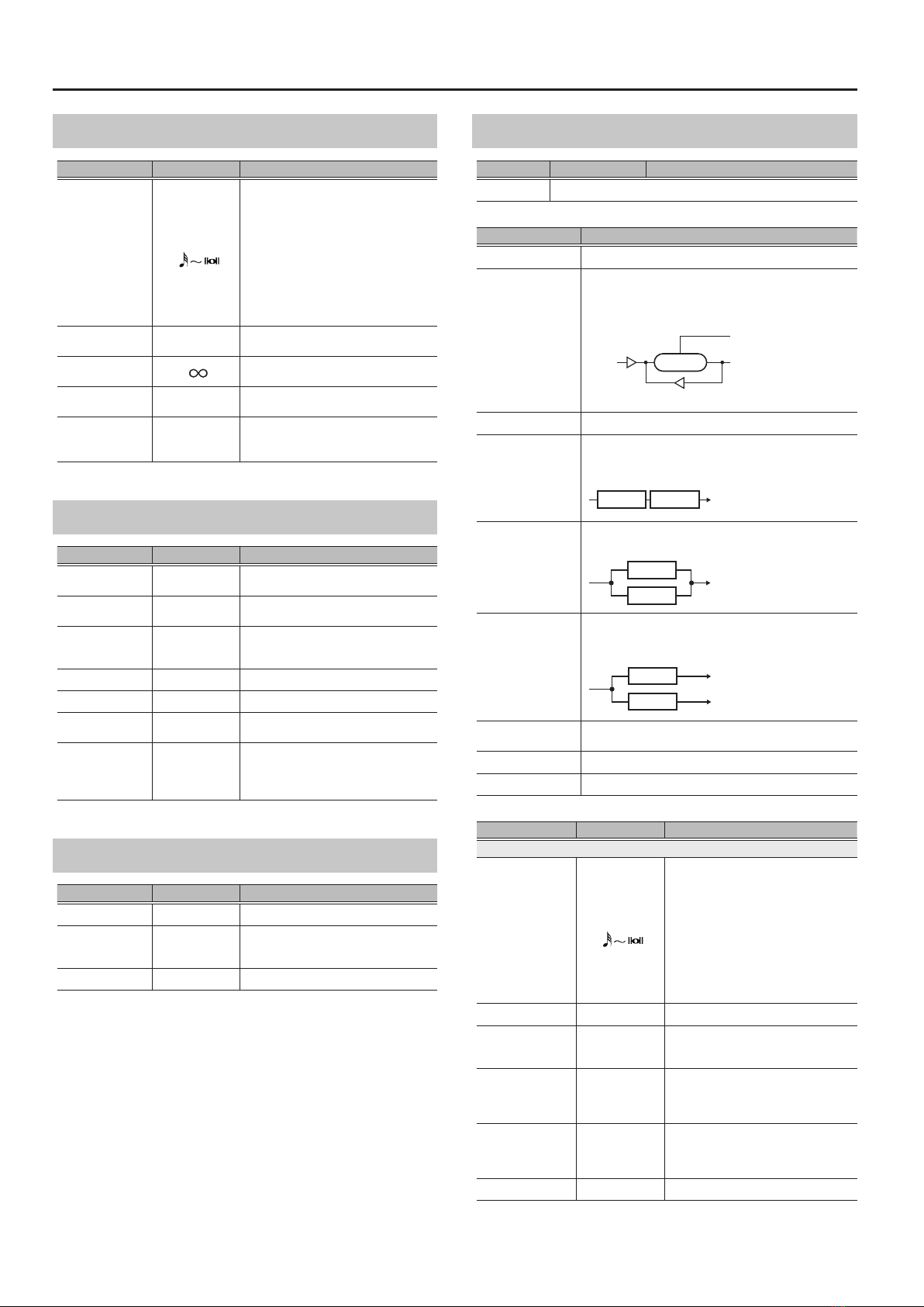
DELAY
Parameter Value Explanation
TYPE Refer to DLY TYPE
DELAY TYPE Explanation
SINGLE This is a simple mono delay.
PAN
This delay is specically for stereo output. This allows you
to obtain the tap delay eect that divides the delay time,
then deliver them to L channel and R channel.
INPUT
OUTPUT L
OUTPUT R
FEEDBACK
DELAY TIME
EFFECT LEVEL
DELAY
TAP TIME
STEREO This is a stereo-in/out delay.
DUAL-S
(DUAL-SERIES)
This is a delay comprising two dierent delays connected
in series. Each delay time can be set in a range from 1 ms
to 2000 ms.
D1 D2 D1: DELAY 1
D2: DELAY 2
DUAL-P
(DUAL-PARALLEL)
This is a delay comprising two delays connected in parallel.
Each delay time can be set in a range from 1 ms to 2000 ms.
D1
D2
DUAL-L/R
This is a delay with individual settings available for L
channel and R channel. Delay 1 goes to L channel, Delay 2
to R channel.
D1
D2
L
R
REVERSE This produces an eect where the sound is played back in
reverse.
MOD This delay adds a pleasant wavering eect to the sound.
WARP Produces a dream-like sound.
Parameter Value Explanation
Common to SINGLE, PAN, STEREO, REVERSE, MOD
TIME
(DELAY TIME)
1–2000ms,
BPM
Adjusts the delay time.
* When set to BPM, the value of each
parameter will be set according to
the value of the “MASTER BPM”(p. 16)
specied for each patch. This makes it
easier to achieve eect sound settings
that match the tempo of the song.
* If, due to the tempo, the time is longer
than the range of allowable settings, it
is then synchronized to a period either
1/2 or 1/4 of that time.
E.LEVEL 0–120 Adjusts the volume of the delay sound.
FEEDBACK 0–100
Adjusts the volume that is returned to
the input. A higher value will increase
the number of the delay repeats.
LOW CUT FLAT,
20–800Hz
This sets the frequency at which the low
cut lter begins to take eect. When
“FLAT” is selected, the low cut lter will
have no eect.
HIGH CUT 630Hz–12.5kHz,
FLAT
This sets the frequency at which the
high cut lter begins to take eect.
When “FLAT” is selected, the high cut
lter will have no eect.
D.LEVEL 0–100 Adjusts the volume of the direct sound.

13
EFFECT
Parameter Value Explanation
DK SENS
(DUCK SENS) 0–100
Adjusts the sensitivity at which the
volume is automatically adjusted
according to the input. Higher values
allow the adjustment to occur in
response to lower volumes.
DK DEPTH
(DUCK DEPTH) 0–100
When the input sound is loud, this
automatically reduces the volume that
is being output from the delay. As this
value is increased, the ducking eect
becomes deeper.
PAN only
TAP TIME 0–100%
Adjusts the delay time of L channel
delay.
This setting adjusts L channel delay
time relative to R channel delay time
(considered as 100%).
MOD only
MOD RATE 0–100 Adjusts the modulation rate of the delay
sound.
MOD DEPTH 0–100 Adjusts the modulation depth of the
delay sound.
Common to DUAL-S, DUAL-P, DUAL-L/R
TIME1
(DELAY TIME)
1–2000ms,
BPM
Adjusts the delay time.
* When set to BPM, the value of each
parameter will be set according to
the value of the “MASTER BPM”(p. 16)
specied for each patch. This makes it
easier to achieve eect sound settings
that match the tempo of the song.
* If, due to the tempo, the time is longer
than the range of allowable settings, it
is then synchronized to a period either
1/2 or 1/4 of that time.
E.LEVEL1 0–120 Adjusts the volume of the delay sound.
FEEDBACK1 0–100
Adjusts the volume that is returned to
the input. A higher value will increase
the number of the delay repeats.
LOW CUT1 FLAT,
20–800Hz
This sets the frequency at which the low
cut lter begins to take eect. When
“FLAT” is selected, the low cut lter will
have no eect.
HIGH CUT1 630Hz–12.5kHz,
FLAT
This sets the frequency at which the
high cut lter begins to take eect.
When “FLAT” is selected, the high cut
lter will have no eect.
TIME2
(DELAY TIME)
1–2000ms,
BPM
Adjusts the delay time.
* When set to BPM, the value of each
parameter will be set according to
the value of the “MASTER BPM”(p. 16)
specied for each patch. This makes it
easier to achieve eect sound settings
that match the tempo of the song.
* If, due to the tempo, the time is longer
than the range of allowable settings, it
is then synchronized to a period either
1/2 or 1/4 of that time.
E.LEVEL2 0–120 Adjusts the volume of the delay sound.
FEEDBACK2 0–100
Adjusts the volume that is returned to
the input. A higher value will increase
the number of the delay repeats.
LOW CUT2 FLAT,
20–800Hz
This sets the frequency at which the low
cut lter begins to take eect. When
“FLAT” is selected, the low cut lter will
have no eect.
HIGH CUT2 630Hz–12.5kHz,
FLAT
This sets the frequency at which the
high cut lter begins to take eect.
When “FLAT” is selected, the high cut
lter will have no eect.
D.LEVEL 0–100 Adjusts the volume of the direct sound.
DK SENS
(DUCK SENS) 0–100
Adjusts the sensitivity at which the
volume is automatically adjusted
according to the input. Higher values
allow the adjustment to occur in
response to lower volumes.
Parameter Value Explanation
DK DEPTH
(DUCK DEPTH) 0–100
When the input sound is loud, this
automatically reduces the volume that
is being output from the delay. As this
value is increased, the ducking eect
becomes deeper.
WARP only
TRIGGER OFF, ON
When this turns “ON,”the WARP eect
is applied.
* It is assumed that this parameter will
be assigned to the footswitch (p. 17).
LEVEL 0–100 Adjusts the volume of the delay sound.
REVERB
Parameter Value Explanation
TYPE
AMBIENCE
Selects the reverb type.
ROOM
HALL
PLATE
MOD
TIME 0.1–10.0s Adjusts the length (time) of reverberation.
E.LEVEL 0–100 Adjusts the volume of the reverb sound.
PRE-DELAY 0–100ms Adjusts the time until the reverb sound
appears.
LOW CUT FLAT,
20–800Hz
This sets the frequency at which the low
cut lter begins to take eect. When
“FLAT” is selected, the low cut lter will
have no eect.
HIGH CUT 630Hz–12.5kHz,
FLAT
This sets the frequency at which the high
cut lter begins to take eect. When
“FLAT” is selected, the high cut lter will
have no eect.
DENSITY 0–10 Adjusts the density of the reverb sound.
D.LEVEL 0–100 Adjusts the volume of the direct sound.

14
EFFECT
REV1/REV2
REV lets you choose a variety of types of reverb. Dierent settings can
simulate a variety of acoustical spaces.
Parameter Value Explanation
ON/OFF OFF, ON Turns this eect on/o.
TYPE Refer to REV TYPE
How to chooseTYPE
1. Press the [EFFECT EDIT] button.
2. Choose “REV1”–“REV2” with the [1] knob.
3. Press the [ENTER] button to move to the edit
screen.
4. Press the [< PAGE] [PAGE >] buttons to move the
rst page.
5. Choose “TYPE”with the [1] knob.
REV TYPE
This is a list of the eects that can be selected for REV.
Eect name Explanation
AMBIENCE
Simulates an ambience mic (o-mic, placed at a distance from
the sound source) used in recording and other applications.
Rather than emphasizing the reverberation, this reverb is used
to produce a sense of openness and depth.
ROOM Simulates the reverberation in a small room. Provides warm
reverberations.
HALL Simulates the reverberation in a concert hall. Provides clear and
spacious reverberations.
PLATE
Simulates plate reverberation (a reverb unit that uses the
vibration of a metallic plate). Provides a metallic sound with a
distinct upper range.
MOD This reverb adds the wavering sound found in hall reverb to
provide an extremely pleasant reverb sound.
DELAY This eect adds delayed sound to the direct sound, giving more
body to the sound or creating special eects.
Common to AMBIENCE, ROOM, HALL, PLATE,
MOD
Parameter Value Explanation
TIME 0.1–10.0s Adjusts the length (time) of reverberation.
LEVEL 0–100 Adjusts the volume of the reverb sound.
PRE-DELAY1 0–200ms Adjusts the time until the reverb sound
appears.
LOW CUT FLAT,
20–800Hz
This sets the frequency at which the low
cut lter begins to take eect. When
“FLAT” is selected, the low cut lter will
have no eect.
HIGH CUT 630Hz–12.5kHz,
FLAT
This sets the frequency at which the high
cut lter begins to take eect. When
“FLAT” is selected, the high cut lter will
have no eect.
DENSITY 0–10 Adjusts the density of the reverb sound.
PRE-DELAY2 OFF, 0–500ms
Adjusts the time until the reverb sound
appears. By combining this with PRE-
DELAY1, you can produce an eect
as though multiple reverbs are being
applied.
DELAY
Parameter Value Explanation
TIME
(DELAY TIME)
1–2000ms,
BPM
Adjusts the delay time.
* When set to BPM, the value of each
parameter will be set according to
the value of the “MASTER BPM”(p. 16)
specied for each patch. This makes it
easier to achieve eect sound settings
that match the tempo of the song.
* If, due to the tempo, the time is longer
than the range of allowable settings, it
is then synchronized to a period either
1/2 or 1/4 of that time.
E.LEVEL 0–120 Adjusts the volume of the delay sound.
FEEDBACK 0–100
Adjusts the amount of delay sound
returned to the input. A higher value will
increase the number of the delay repeats.
LOW CUT FLAT,
20–800Hz
This sets the frequency at which the low
cut lter begins to take eect. When
“FLAT” is selected, the low cut lter will
have no eect.
HIGH CUT 630Hz–12.5kHz,
FLAT
This sets the frequency at which the high
cut lter begins to take eect. When
“FLAT” is selected, the high cut lter will
have no eect.
15
EFFECT
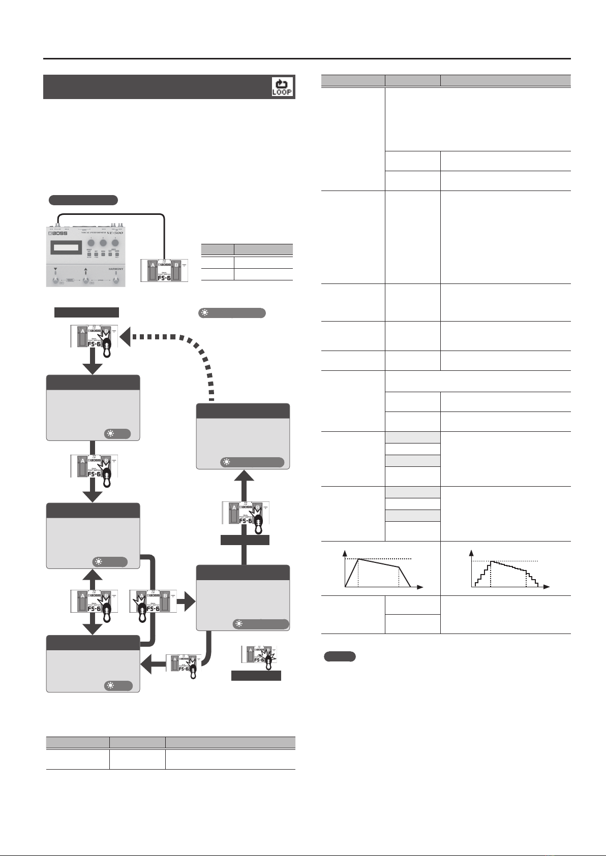
LOOP
LOOP (LOOPER) records your vocal and repeatedly plays back that
content. You can also overdub-record (layer) an additional vocal onto
the repeating playback. Alternatively, you can sing over the backing
of the recorded content.
When using LOOPER, make CTL settings to assign the LOOPER
function to a footswitch such as CTL1 or CTL2.
Setting example
CTL2 CTL1
Pedal Func (p. 17)
CTL1 REC/PLAY1
CTL2 STOP
REC ACTION : REC->DUB
PDL MODE : LATCH
Indicator display
Record (REC)
Recording will start immediately
when you press the [CTL1] pedal.
At the point where you want to
loop, press the pedal to switch to
overdubbing.
Loop Playback (PLAY)
Play back the loop.
Pressing the [CTL1] pedal to switch
to overdubbing.
Overdub (DUB)
Record additional layers while
playing back the loop.
Press the [CTL1] pedal to switch to
playback.
CLEAR
While stopped, you can clear
the phrase by long-pressing the
[CTL1] switch.
CTL2
CTL1
CTL1
CTL1
CTL1
CTL1
CTL1
STOP
Press the [CTL2] switch to stop.
Alternatively, press the [CTL1]
switch twice.
Start recording
Long-press
Press Twice
Red
Purple
Blue
Blinking blue
Blinks red twice
* This is the state of the
indicator when the unit’s
switch is assigned to FUNC.
* Operation depends on the selected FUNC and on the REC
ACTION and PDL MODE setting.
Parameter Value Explanation
1SHOT OFF, ON Species whether to use conventional
loop playback or one-shot playback.
Parameter Value Explanation
REC ACTION
Species how recording operation.
Species whether, when you press the switch that is
assigned to REC/PLAY, operations occur in the order of
Recording 0Overdub 0Playback or in the order of
Recording 0Playback 0Overdub.
* This cannot be selected if 1SHOT is“ON” or if PDL MODE is
“MOMENT.”
REC->DUB Operation will switch in the order of
Recording0Overdub0Playback.
REC->PLAY Operation will switch in the order of
Recording0Playback0Overdub.
LEVEL
(PLAY LEVEL) 0–200
Species the playback volume for
LOOPER. If you set the playback level
at 100 (default value), the volume of
the performance and that of the loop
playback will be identical. If you set the
playback level to a value lower than 100,
the volume of the playback will be lower
than that of the performance. As a result,
the sound of the performance won’t get
buried by the loop playback sound, even
if you record a multiple number of times.
LOOP LENGTH
FREE, 1/16–15/16,
1MEAS, 5/4–7/4,
2–24MEAS
Species the length that is loop-recorded.
If this is set to “FREE,” the loop length
is determined by the timing of your
operations.
PLAYBACK
LENGTH FREE, 1–64
Species the number of times that loop
playback occurs.
* This cannot be selected if 1SHOT is“ON.”
PLAYBACK DECAY -50–+50 Species the decay amount of the sound
during loop playback.
FADE MODE
Selects the fade-in (out) type.
* This cannot be selected if 1SHOT is“ON.”
LOOP The playback volume changes for the
entire length of the loop.
LINEAR The playback volume changes during the
specied length.
FADE IN
MODE = LOOP
This species the fade-in time.
OFF, 1–10
MODE = LINEAR
OFF, 1/16–15/16, 1,
5/4–7/4, 2–24
FADE OUT
MODE = LOOP
This species the fade-out time.
OFF, 1–10
MODE = LINEAR
OFF, 1/16–15/16, 1,
5/4–7/4, 2–24
PDL MODE
LATCH Species the operation that occurs when
you operate a controller to which the CTL
setting assigns REC/PLAY1 or REC/PLAY2
(p. 17).
MOMENT
MEMO
* The recording time is 60 seconds (MONO) / 30 seconds
(STEREO).
* The recorded content is lost when you change patches, switch
the LOOP MODE, turn o the power, or perform a similar
operation.
PLAY
LEVEL DECAY
FADE IN FADE OUT
LEVEL
FADE MODE : LINEAR
TIME
PLAY
LEVEL DECAY
FADE IN FADE OUT
LEVEL
FADE MODE : LOOP
TIME

16
EFFECT
KEY SETTING
Here you can make key-related settings.
HARMONY
Parameter Value Explanation
AUTO
Selects how harmony is added.
* Try the FULL setting, and if you don’t get the harmony
that you expect, use the HYBRID setting. If you’re not
using a guitar, turn this OFF and specify the key.
FULL
Harmony is added according to the chords
and the chord progression that you play
on your guitar.
HYBRID
Harmony is added according to the “KEY”
setting and the chords that you play on
your guitar.
OFF Harmony is added according to the “KEY”
setting.
KEY C –Bm
Specify the key of the song that you’re
singing.
Major
Major
Minor
Minor
RECG SRC
Selects the source from which the chord or chord
progression is detected.
AUTO The chord or chord progression is
detected from sound received via all jacks.
INST
The chord or chord progression is
detected from sound received at the INST
INPUT jack.
MIDI
The chord or chord progression is
detected from note messages received at
the MIDI IN connector.
MIDI (USB)
The chord or chord progression is
detected from note messages received at
the USB port.
M>CHRD
(MIDI TO CHORD)
The chord is detected from received MIDI note messages.
* This is valid if LFX TYPE is “HARMONY” and RECG SRC is
set to something other than “INST.”
Ch.1–16 The chord is detected from note messages
of the specied MIDI channel.
RX
The chord is detected from note message
of the MIDI channel specied by the
SYSTEM MIDI setting RX CH.
OFF O
ZONE LO
(ZONE LOWER)
C1–G9 Species the range in which note
messages are accepted.
ZONE UP
(ZONE UPPER)
C1–G9
BEND 0–12
Species the degree of pitch change in
semitones when the Pitch Bend lever is all
the way right (left).
For example if this is set to “12” and you
move the pitch bend lever all the way to
the right (left), the pitch will rise (fall) 1
octaves.
VOCODER
Parameter Value Explanation
BEND 0–12
Species the degree of pitch change in
semitones when the Pitch Bend lever is all
the way right (left).
For example if this is set to “12” and you
move the pitch bend lever all the way to
the right (left), the pitch will rise (fall) 1
octaves.
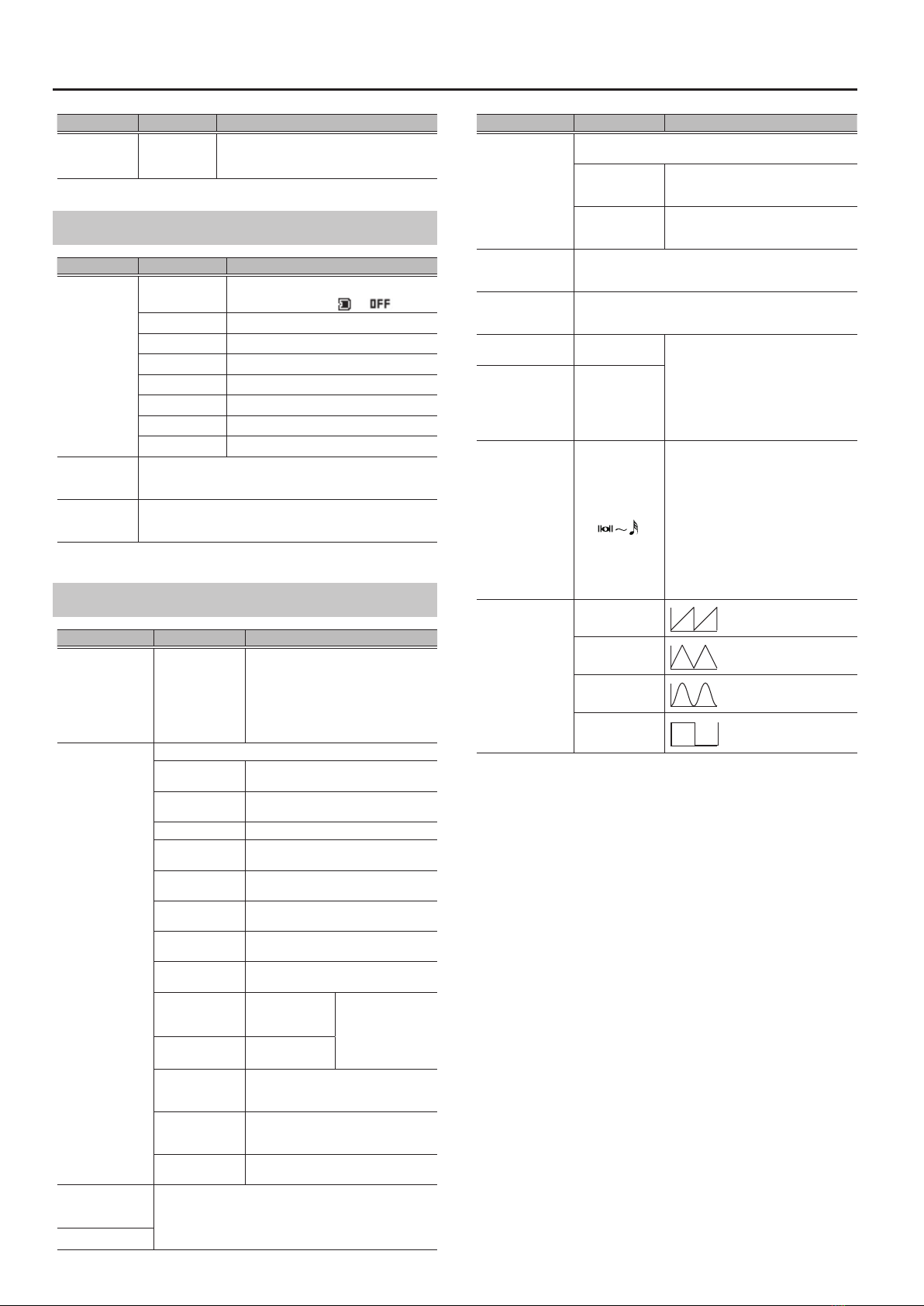
MASTER
These are settings for the entire patch.
Parameter Value Explanation
BPM
(MASTER BPM)
10–500
Adjusts the BPM value for each patch.
* BPM (beats per minute) indicates the
number of quarter note beats that occur
each minute.
NS 0–100 Adjusts the depth of the noise suppressor.
PAT LEV 0–200 Sets the patch volume.
FX STRUCTURE
Selects the connection order of FX1–4.
SERIES
LEAD Multi-FX
FX1 FX2 FX3 FX4
HARMONY1
HARMONY2
HARMONY3
FX OUT1
PARA+SER
LEAD Multi-FX
FX OUT1
FX1
FX2
FX3 FX4
HARMONY1
HARMONY2
HARMONY3
2PARALLEL
LEAD Multi-FX FX OUT1
FX OUT2
FX1 FX2
FX3 FX4
HARMONY1
HARMONY2
HARMONY3
4PARALLEL
LEAD Multi-FX FX OUT1
FX OUT2
FX OUT3
FX OUT4
FX1
FX2
FX3
FX4
HARMONY1
HARMONY2
HARMONY3
* This can be selected if HARMONY/
VOCODER TYPE is “HARMONY.”
REVERB STRUCTURE
Selects the connection order of REV1 and REV2.
SERIES
FX OUT1 Reverb
FX OUT
REV/
DLY1
REV/
DLY2
FX OUT2
FX OUT3
FX OUT4
PARALLEL
FX OUT1 Reverb
FX OUT
REV/
DLY1
REV/
DLY2
FX OUT2
FX OUT3
FX OUT4
SEPARATE
FX OUT1 Reverb
FX OUT
REV/
DLY1
REV/
DLY2
FX OUT2
FX OUT3
FX OUT4
REVERB LEVEL 0–200 Adjusts the overall volume level of the
reverb section.
LOOP MODE
Selects the playback mode of looper.
MONO The looper plays back in mono.
STEREO The looper plays back in stereo.
17
EFFECT
Parameter Value Explanation
LOOP LOCATION
Selects the position within the unit at which the looper is
located.
MIC IN Located after the mic input.
PRE FX1 Located before FX1.
PRE FX2 Located before FX2.
PRE FX3 Located before FX3.
PRE FX4 Located before FX4.
PRE REV1 Located before REV1.
PRE REV2 Located before REV2.
OUTPUT Located after the master output.
CTL&ASSIGN SETTING
You can set the following items for CTL.
Controller Explanation
-
Species the parameter that is controlled by the [?] and [=]
switches when in Memory mode.
* This works only in Memory mode.
-
Species the parameter that is controlled by the [?] ([FX1]) and
[=] ([FX2]) switches when in Manual mode.
* This works only in Manual mode.
Species the parameter that is controlled by the [HARMONY]
switch.
Species the parameter that is controlled by an expression pedal
(EXP) connected to the CTL 1, 2/EXP jack.
-
Species the parameter that is controlled by a footswitch (CTL
1–2) connected to the CTL 1, 2/EXP jack.
Species the parameter that is controlled by pressing the [?] and
[=] switches simultaneously.
Species the parameter that is controlled by pressing the [=] and
[HARMONY] switches simultaneously.
-
ASSIGN allows you to make more detailed settings. For example,
you can use ASSIGN if you want to simultaneously control another
parameter in addition to operating the parameter of the [?]
switch.
You can specify eight dierent settings for each patch.
Common to
DOWN, UP, FX1, FX2, HRM, CTL1, CTL2,
MEM/MAN, BYPASS
Parameter Value Explanation
FUNC
OFF No assignment.
The icon changes from to .
PAT- Switches to the previous patch number.
PAT+ Switches to the next patch number.
EH OnOf Turns EH on/o.
PCR OnOf Turns PCR on/o.
LFX OnOf Turns HRM/VOC on/o.
FX1 OnOf Turns FX1 on/o.
FX2 OnOf Turns FX2 on/o.
Parameter Value Explanation
FUNC
FX3 OnOf Turns FX3 on/o.
FX4 OnOf Turns FX4 on/o.
REV1 OnOf Turns REV1 on/o.
REV2 OnOf Turns REV2 on/o.
TRIG1
(FX1) If the corresponding FX is on, turns the
following parameters on/o.
5TRIGGER within ROLL
5TRIGGER within FREEZE
5TRIGGER within SLICER
5TRIGGER within DELAY/WARP
5TRIGGER within VIBRATO
TRIG2
(FX2)
TRIG3
(FX3)
TRIG4
(FX4)
REC/PLAY1
Species the operation of LOOPER.
If PDL MODE is “LATCH”
Step: REC->DUB-PLAY-DUB
Step twice in succession: stop LOOPER
Long-press: CLEAR operation
If PDL MODE is “MOMENT”
While you hold down: REC or PLAY
Release: stop LOOPER
Step twice in succession: CLEAR operation
REC/PLAY2
Species the operation of LOOPER.
If PDL MODE is “LATCH”
Step: REC->DUB-PLAY-DUB
* There is no STOP / CLEAR operation.
If PDL MODE is “MOMENT”
While you hold down: REC or PLAY
Release: stop LOOPER
* There is no CLEAR operation.
STOP Step: stop LOOPER
Long-press: CLEAR operation
CLEAR Step: clear phrase recorded in LOOPER
BYPS Bypass the eect.
BYPS/TUNR Step: bypass the eect.
Long-press: show the TUNER screen.
TUNER Turns TUNER on/o.
MEM/MAN Switches between memory mode and manual
mode.
BPM TAP
Used for tap input of the master BPM.
The indicator of the assigned switch blinks in
time with the BPM.
FX1 DLY
Used for tap input of the delay time.
The indicator of the assigned switch blinks in
time with the BPM.
FX2 DLY
FX3 DLY
FX4 DLY
REV1 DLY
REV2 DLY
LED
Turns the indicator on/o.
Turns on/o the indicator of the assigned
switch.
MODE
(SOURCE
MODE)
Species how the value changes when you operate the switch.
MOMENT
The normal state is O (minimum value), with
the switch On (maximum value) only while the
switch is depressed.
TOGGLE
The setting is toggled On (maximum value)
or O (minimum value) with each press of the
switch.
ACTION OFF0ON,
ON0OFF
OFF0ON:
On while the switch is held down, and o
when it is not held down.
ON0OFF:
O while the switch is held down, and on
when it is not held down.
* This is valid if MODE is set to“MOMENT.”
18
EFFECT
Parameter Value Explanation
COLOR RED, BLUE,
VIOLET
Set the color of the indicator.
* This can be set if “LED” is selected as FUNC
for DOWN, UP, FX1, FX2, or HRM.
EXP
Parameter Value Explanation
FUNC
(FUNCTION)
OFF No assignment.
The icon changes from to .
PAT LEVEL Adjusts the patch level.
LFX E.LEV Adjusts the LFX level.
REV LEVEL Adjusts the reverb level.
F1TW FREQ Adjusts the freq of T.WAH (FX1).
F2TW FREQ Adjusts the freq of T.WAH (FX2).
F3TW FREQ Adjusts the freq of T.WAH (FX3).
F4TW FREQ Adjusts the freq of T.WAH (FX4).
MIN
This sets the minimum value for the range in which the
parameter can change. The value diers depending on the
parameter assigned for FUNC parameter.
MAX
This sets the maximum value for the range in which the
parameter can change. The value diers depending on the
parameter assigned for FUNC parameter.
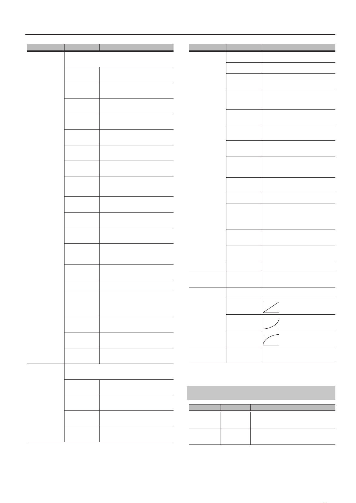
ASSIGN 1–8
Parameter Value Explanation
ASSIGN OFF, ON
Turns the ASSIGN 1–8 on/o.
* If you set SOURCE to WAVE, leave
ASSIGN turned OFF until you nish
making the settings. If this is left
ON, parameters might be switched
unintentionally while you make
settings.
SOURCE
Species the controller (source).
DOWN Assigns the [?] switch when in memory
mode.
UP Assigns the [=] switch when in memory
mode.
HARMONY Assigns the [HARMONY] switch.
FX1 Assigns the [?] ( [FX1] ) switch when in
manual mode.
FX2 Assigns the [=] ( [FX2] ) switch when in
manual mode.
EXP Assigns the expression pedal connected
to the CTL 1, 2/EXP jacks.
CTL1 Assigns the footswitch pedal connected
to CTL1 of the CTL 1, 2/EXP jacks.
CTL2 Assigns the footswitch pedal connected
to CTL2 of the CTL 1, 2/EXP jacks.
INT PDL
(INTERNAL
PEDAL)
Assigns the
internal pedal.
Refer to “Virtual
Expression Pedal
System (Internal
Pedal/Wave Pedal)”
(p. 23)
WAVE PDL
(WAVE PEDAL)
Assigns the wave
pedal.
MIC LEV
The parameter that is assigned as the
target will vary according to the volume
level that is input to the MIC IN jack.
INST LEV
The parameter that is assigned as the
target will vary according to the volume
level that is input to the INST INPUT jack.
CC#1–31, CC#64–95
Assigns the specied MIDI control
change message.
CATEGORY
(TARGET
CATEGORY) Selects the parameter to be changed.
Refer to“Target List” (p. 20).
TARGET
Parameter Value Explanation
MODE
(SOURCE MODE)
Species how the value changes when you operate the
controller.
MOMENT
The normal state is O (minimum value),
with the switch On (maximum value)
only while the control is being operated.
TOGGLE
The setting is toggled On (maximum
value) or O (minimum value) with each
time control is operated.
MIN
(TARGET MIN)
Sets the minimum value for the range in which the
parameter can change. The value diers depending on the
parameter assigned for TARGET parameter.
MAX
(TARGET MAX)
Sets the maximum value for the range in which the
parameter can change. The value diers depending on the
parameter assigned for TARGET parameter.
ACT LOW
(ACT RANGE LOW) 0–126 Sets the controllable range for target
parameters within the source’s
operational range. Target parameters
are controlled within the range set with
ACT LOW and ACT HIGH. You should
normally set ACT LOW to 0 and ACT
HIGH to 127.
ACT HIGH
(ACT RANGE HIGH) 1–127
WAVE RATE *1 0–100,
BPM
Adjusts the time spend for one cycle of
the assumed expression pedal.
* When set to BPM, the value of each
parameter will be set according to
the value of the “MASTER BPM”(p. 16)
specied for each patch. This makes it
easier to achieve eect sound settings
that match the tempo of the song.
* If, due to the tempo, the time is longer
than the range of allowable settings, it
is then synchronized to a period either
1/2 or 1/4 of that time.
WAVE FORM *1
SAW
TRI
SIN
SQR
19
EFFECT
Parameter Value Explanation
WAVE TRIG
(WAVE PEDAL
TRIGGER) *1
Species the controller that resets the wave pedal to the start
point.
OFF The start point of the wave pedal will not
be reset.
DOWN This is activated when the [?] switch is
operated while in memory mode.
UP This is activated when the [=] switch is
operated while in memory mode.
HARMONY This is activated when the [HARMONY]
switch is operated.
FX1 This is activated when the [?] ( [FX1] )
switch is operated while in manual mode.
FX2 This is activated when the [=] ( [FX2] )
switch is operated while in manual mode.
EXP LOW
This is activated when the expression
pedal (EXP) connected to the CTL 1, 2/
EXP jacks is minimized.
EXP MID
This is activated when the expression
pedal (EXP) connected to the CTL 1, 2/
EXP jacks is operated to pass through the
middle position.
EXP HIGH
This is activated when the expression
pedal (EXP) connected to the CTL 1, 2/
EXP jacks is maximized.
CTL1
This is activated when the footswitch
connected to CTL1 of the CTL 1, 2/EXP
jacks is operated.
CTL2
This is activated when the footswitch
connected to CTL2 of the CTL 1, 2/EXP
jacks is operated.
MIC IN L
This is activated by the volume that is
input to the MIC IN jack (input level low).
* This is activated when it falls below a
certain level.
MIC IN M
This is activated by the volume that
is input to the MIC IN jack (input level
medium).
MIC IN H This is activated by the volume that is
input to the MIC IN jack (input level high).
INST IN L
This is activated by the volume that is
input to the INST INPUT jack (input level
low).
* This is activated when it falls below a
certain level.
INST IN M
This is activated by the volume that is
input to the INST INPUT jack (input level
medium).
INST IN H
This is activated by the volume that is
input to the INST INPUT jack (input level
high).
CC#1–31, CC#64–95
This is activated when the specied MIDI
control change message is received.
INT TRIG
(INTERNAL PEDAL
TRIGGER) *2
This species what triggers the internal pedal to start
operating.
PATCH CHG
(PATCH CHANGE) This is activated when a patch is selected.
DOWN This is activated when the [?] switch is
operated while in memory mode.
UP This is activated when the [=] switch is
operated while in memory mode.
HARMONY This is activated when the [HARMONY]
switch is operated.
Parameter Value Explanation
INT TRIG
(INTERNAL PEDAL
TRIGGER) *2
FX1 This is activated when the [?] ( [FX1] )
switch is operated while in manual mode.
FX2 This is activated when the [=] ( [FX2] )
switch is operated while in manual mode.
EXP LOW
This is activated when the expression
pedal (EXP) connected to the CTL 1, 2/
EXP jacks is minimized.
EXP MID
This is activated when the expression
pedal (EXP) connected to the CTL 1, 2/
EXP jacks is operated to pass through the
middle position.
EXP HIGH
This is activated when the expression
pedal (EXP) connected to the CTL 1, 2/
EXP jacks is maximized.
CTL1
This is activated when the footswitch
connected to CTL1 of the CTL 1, 2/EXP
jacks is operated.
CTL2
This is activated when the footswitch
connected to CTL2 of the CTL 1, 2/EXP
jacks is operated.
MIC IN L
This is activated by the volume that is
input to the MIC IN jack (input level low).
* This is activated when it falls below a
certain level.
MIC IN M
This is activated by the volume that
is input to the MIC IN jack (input level
medium).
MIC IN H This is activated by the volume that is
input to the MIC IN jack (input level high).
INST IN L
This is activated by the volume that is
input to the INST INPUT jack (input level
low).
* This is activated when it falls below a
certain level.
INST IN M
This is activated by the volume that is
input to the INST INPUT jack (input level
medium).
INST IN H
This is activated by the volume that is
input to the INST INPUT jack (input level
high).
CC#1–31, CC#64–95
This is activated when the specied MIDI
control change message is received.
INT TIME *2 0–100
This species the time over which the
internal pedal will move from the toe-
raised position to the toe-down position.
INT CURVE *2
Select one of the following curves to specify the change
produced by the internal pedal.
LINEAR
SLOW
FAST
CC#
1–31, 64–95
If TARGET is set to MIDI CC, the MIDI
control change message of the specied
number is output.
*1 Available if SOURCE is set to WAVE PDL.
*2 Available if SOURCE is set to INT PDL.
ASSIGN COMMON
Parameter Value Explanation
MIC SENS 0–100
Adjusts the sensitivity when SOURCE is set to
MIC LEV, WAVE TRIG MIC IN (L/M/H), or INT TRIG
MIC IN (L/M/H).
INST SENS 0–100
Adjusts the sensitivity when SOURCE is set to
INST LEV, WAVE TRIG INST IN (L/M/H) or INT
TRIG INST IN (L/M/H).
20
EFFECT
CATEGORY Target
ENHANCE
ON/OFF
ENHANCE
COMPRESS
DE-ESSER
EQ LOW GAIN
EQ HI GAIN
EQ LEVEL
EQ LM GAIN
EQ LM FREQ
EQ LM Q
EQ HM GAIN
EQ HM FREQ
EQ HM Q
EQ LOW CUT
EQ HIGH CUT
PCR
ON/OFF
TYPE
SCALE
FORMANT
SHIFT
SPEED
STABILITY
NOTE
LFX
ON/OFF
TYPE
E.LEVEL
D.LEVEL
HARMONY
ON/OFF
NOTE SENS
USRINT1 C
USRINT1 Db
USRINT1 D
USRINT1 Eb
USRINT1 E
USRINT1 F
USRINT1 F#
USRINT1 G
USRINT1 Ab
USRINT1 A
USRINT1 Bb
USRINT1 B
USRINT2 C
USRINT2 Db
USRINT2 D
USRINT2 Eb
USRINT2 E
USRINT2 F
USRINT2 F#
USRINT2 G
USRINT2 Ab
USRINT2 A
USRINT2 Bb
USRINT2 B
USRINT3 C
USRINT3 Db
USRINT3 D
USRINT3 Eb
USRINT3 E
USRINT3 F
USRINT3 F#
USRINT3 G
CATEGORY Target
HARMONY
USRINT3 Ab
USRINT3 A
USRINT3 Bb
USRINT3 B
USRINT4 C
USRINT4 Db
USRINT4 D
USRINT4 Eb
USRINT4 E
USRINT4 F
USRINT4 F#
USRINT4 G
USRINT4 Ab
USRINT4 A
USRINT4 Bb
USRINT4 B
HARMONY1
VOICE AUTO
VOICE MANU
PAN
LEVEL
DOUBLE
DELAY
ACCURACY
VIBRATO
METHOD
FORMANT
TONE
HARMONY2
VOICE AUTO
VOICE MANU
PAN
LEVEL
DOUBLE
DELAY
ACCURACY
VIBRATO
METHOD
FORMANT
TONE
HARMONY3
VOICE AUTO
VOICE MANU
PAN
LEVEL
DOUBLE
DELAY
ACCURACY
VIBRATO
METHOD
FORMANT
TONE
VOCODER
ON/OFF
SOURCE
TYPE
LEVEL
CARR. INST
CARR. MIC
OCTAVE
DRIVE
FORMANT
TONE
ATTACK
RELEASE
VOCODER CHROMATIC
VEL SENS
FX1 ON/OFF
TYPE
CATEGORY Target
FX1 DIST
DIST
TONE
E.LEVEL
D.LEVEL
FX1 RADIO LO-FI
LEVEL
FX1 LO-FI
BIT
SAMPLE
BALANCE
FX1 FILTER
TYPE
RATE
LEVEL
DEPTH
RESONANCE
CUTOFF
STEP RATE
MODE
FX1 T.WAH
TYPE
POLARITY
SENS
FREQ
PEAK
E.LEVEL
D.LEVEL
FX1 RNGMD
FREQ
E.LEVEL
D.LEVEL
FX1 CHO
TYPE
RATE
DEPTH
E.LEVEL
PRE-DELAY
LOW CUT
HIGH CUT
D.LEVEL
FX1 FLANGR
RATE
DEPTH
RESONANCE
MANUAL
SEPARAT
LOW CUT
E.LEVEL
D.LEVEL
STEP RATE
FX1 TREMOL
WAVE
RATE
DEPTH
LEVEL
FX1 PHASE
TYPE
RATE
DEPTH
RESONANCE
MANUAL
STEP RATE
E.LEVEL
D.LEVEL
FX1 ROTARY
SPEED
RATE SLOW
RATE FAST
DEPTH
RISE TIME
FALL TIME
E.LEVEL
CATEGORY Target
FX1 SLICER
PATTERN
RATE
DUTY
DEPTH
ATTACK
TRIGGER
FX1 ISOLAT
BAND
RATE
DEPTH
BAND LEVEL
STEP RATE
FX1 VIB
RATE
DEPTH
TRIGGER
RISE TIME
LEVEL
FX1 PAN
TYPE
POSITION
LEVEL
WAVE
RATE
DEPTH
INIT PHASE
FX1 ROLL
TIME
ROLL
REPEAT
BALANCE
TRIGGER
FX1 FREEZE
LENGTH
ATTACK
RELEASE
DECAY
SUSTAIN
BALANCE
TRIGGER
FX1 GRANU
TIME
FEEDBACK
LEVEL
FX1 DELAY
TYPE
TIME
E.LEVEL
FEEDBACK
LOW CUT
HIGH CUT
TAP TIME
MOD RATE
MOD DEPTH
D.LEVEL
DK SENS
DK DEPTH
TAP
FX1 D-DUAL
TIME1
E.LEVEL1
FEEDBACK1
LOW CUT1
HIGH CUT1
TIME2
E.LEVEL2
FEEDBACK2
LOW CUT2
HIGH CUT2
FX1 D-WRP WARP TRIG
WARP LEV
Target List
Other manuals for VE-500
1
This manual suits for next models
1
Table of contents
Other BOSSCO Stereo System manuals


