BOSSCO SY-200 User manual

2
Panel Descriptions
Top Panel
1 2
3 4 5
6 7 8 9
10 11
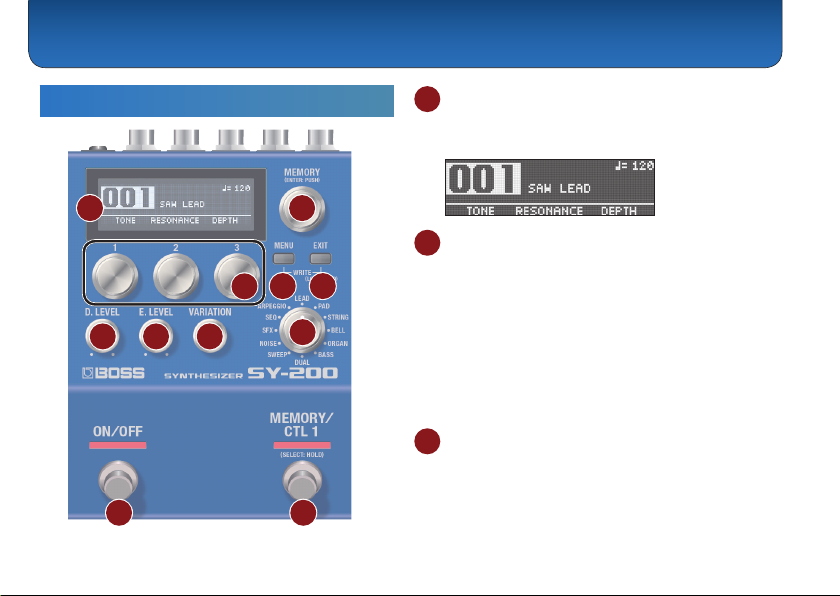
1 Display
Displays various information such as the current
memory number.
2 [MEMORY] knob
MEMORY (turn the knob)
Turn the knob to switch between memories 1–128
(p. 7).
To change a value in larger steps, turn a knob while
pressing it.
ENTER (press the knob)
Press this knob to conrm the setting or perform other
tasks.
3 [1]–[3] knobs
Use these knobs to set the parameter values shown in
the screen.
To change a value in larger steps, turn a knob while
pressing it.

Panel Descriptions
3
4 [MENU] button
The menu screen appears.
5 [EXIT] button
Returns you to the previous screen. In some screens,
this cancels the function currently being executed.
Preventing accidental operation (panel lock)
By holding down the [EXIT] button, you can switch
between enabling (unlocking) or disabling (locking) the
knobs and buttons.
If you use these controls while the unit is locked, the
display indicates “LOCKED.”
MEMO
Press both the [MENU] and [EXIT] buttons together to
display the WRITE UTILITY screen, where you can save,
exchange and initialize the memories (p. 7).
6 [D. LEVEL] knob
This adjusts the volume of the direct sound.
7 [E. LEVEL] knob
This adjusts the volume of the eect sound (synth
sound).
8 [VARIATION] knob
This selects variations for the type that is selected.
9 Type knob
Use this knob to switch between dierent synth sound
types.
Type Explanation
LEAD Suitable for playing solos or leads
PAD Soft sounds used as sonic ll-ins
STRING Synth strings sounds
BELL Sounds with metallic resonance
ORGAN Organ sounds
BASS Bass synth sounds
DUAL Fat sounds
SWEEP Sounds with a characteristic vibration
NOISE Noise sounds
SFX Sound eects and distinctive sounds
SEQ Sounds whose pitch or character changes
rhythmically
ARPEGGIO Arpeggio phrases that play
Panel Descriptions
4
10 [ON/OFF] switch
Turns the eect (synth sound) on/o.
11 [MEMORY/CTL 1] switch
Switches between memories (p. 7).
Holding this down makes it function as the [CTL 1]
switch.
MEMO
You can change the footswitch function with the
“FUNCTION” (ON/OFF FUNCTION/CTL FUNCTION) parameter.
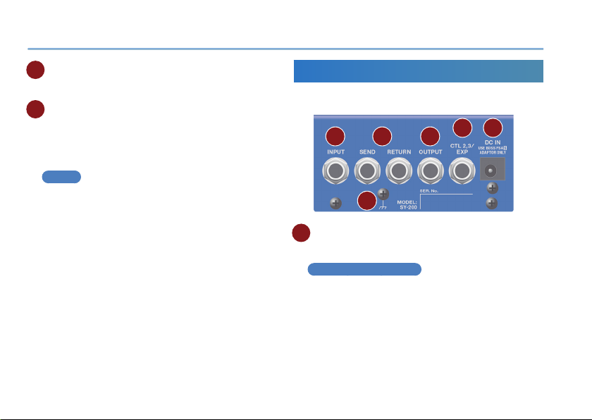
Rear Panel
* To prevent malfunction and equipment failure, always turn down the
volume, and turn o all the units before making any connections.
A B C D E
F
A INPUT jack
Connect your guitar, bass, or eect unit here.
Turning on/o the power
The INPUT jack also serves as the power switch. The
power turns on when you insert a plug into the INPUT
jack.

Panel Descriptions
5
* Once everything is properly connected (p. 4), be sure to follow the
procedure below to turn on their power. If you turn on equipment in
the wrong order, you risk causing malfunction or equipment failure.
* Before turning the unit on/o, always be sure to turn the volume down.
Even with the volume turned down, you might hear some sound when
switching the unit on/o. However, this is normal and does not indicate
a malfunction.
When powering up
Turn on equipment such as your guitar amp last.
When powering down
Turn o equipment such as your guitar amp rst.
B SEND/RETURN jacks
This unit sends signals from the SEND jack to an
external eect unit, and receives signals from an
external eect unit via the RETURN jack.
You can switch the SEND/RETURN function using
the “SEND/RETURN” parameter.
C OUTPUT jack
Connect this jack to your amp or monitor speakers.
D CTL 2, 3/EXP jack
Using the jack as CTL 2/3
You can connect a footswitch (sold separately: FS-5U,
FS-6 or FS-7) and assign it to control a variety of
functions (p. 9).
Using the jack as EXP
You can connect an expression pedal (EV-30, Roland
EV-5 or similar, sold separately) and use it to control the
volume or tonal character of the synth sound (p. 12).
* Use only the specied expression pedal. By connecting any other
expression pedals, you risk causing malfunction and/or damage
to the unit.
E DC IN jack
Use this jack to connect an AC adaptor (PSA-S series,
sold separately).
* Use only the specied AC adaptor (sold separately: PSA-S series)
and plug it into an AC outlet of the correct voltage.
* If the AC adaptor is connected while the batteries are installed, the
power supply is drawn from the AC adaptor.
F Ground terminal
* Connect this to an external earth or ground if necessary.
Panel Descriptions
6
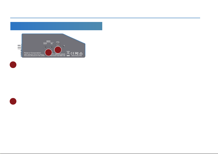
Side Panel
G H
G MIDI jacks
Use a TRS/MIDI connecting cable (BMIDI-5-35, sold
separately) to connect an external MIDI device. You
can use an external MIDI device to switch between
memories on this unit.
* Do not connect an audio device here. Doing so will cause
malfunctions.
H USB port
Connect your computer using a commercially available
USB cable that supports USB 2.0.
* Do not use a micro USB cable that is designed only for charging a
device. Charge-only cables cannot transmit data.
* Used only for updating programs.
7
Saving to a Memory
You can save the settings you’ve edited.
1. Press the [MENU] and [EXIT] buttons at the
same time.
The WRITE UTILITY screen appears.
2. Use the [1] knob to select “WRITE.”
3. Use the [1] knob to select the memory (1–128)
to which you will save the settings, and press
the [MEMORY] knob.
You can also edit the name here.
Controller Operation
[1] knob Edits the character.
[2] knob Moves the cursor.
[3] knob Changes the character type.
[MENU] button Delete one character
4. Press the [MEMORY] knob.
The current settings are saved.
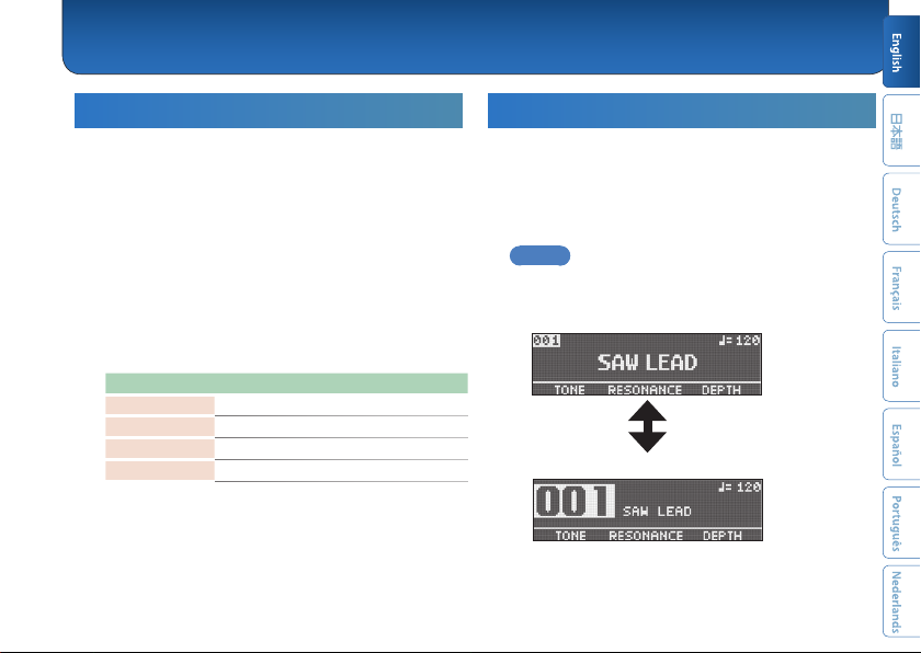
Switching Between Memories
Here’s how to recall a saved memory.
1. Turn the [MEMORY] knob.
The memory number changes in ascending order (1
02 03 04... 128).
MEMO
5Hold down the [MEMORY] knob to switch between screen
displays.
Memory number displayed larger
Memory name displayed larger
5Turn the [MEMORY] knob to move the cursor and edit the
tempo.
Saving and Switching Between Memories

Saving and Switching Between Memories
8
Exchanging Memories
You can change the order of saved memories by
exchanging them.
1. Turn the [MEMORY] knob to select the memory
to exchange.
2. Press the [MENU] and [EXIT] buttons at the
same time.
The WRITE UTILITY screen appears.
3. Press the [2] knob and select “EXCHANGE.”
4. Turn the [1] knob to select the memory to
exchange.
5. Press the [MEMORY] knob.
This exchanges the memories you selected in steps
1 and 4.
Initializing a Memory
You can return (initialize) a memory to its standard
settings. This is useful when you want to create a new
tone from scratch.
1. Turn the [MEMORY] knob to select the memory
to initialize.
2. Press the [MENU] and [EXIT] buttons at the
same time.
The WRITE UTILITY screen appears.
3. Use the [3] knob to select “INITIALIZE.”
The memory is initialized.
9
Various Settings (Menu)
Basic Operations
1. Press the [MENU] button.
The unit enters MENU mode.
2. Press knobs [1], [2] and [3] to select the item
to edit.
Hold down the [MEMORY] knob to switch between
the setting pages.
3. Use the [1], [2], [3] and [MEMORY] knobs to edit
the settings for each item.
4. When editing parameters besides“SYSTEM”
(p. 13),“MIDI” (p. 13), and“MIDI PC MAP”
(p. 14), operate the unit as shown in “Saving
to a Memory”(p. 7).
* If you do not do this, the changes are lost when you switch memories.
5. Press the [EXIT] button.
The unit exits MENU mode.
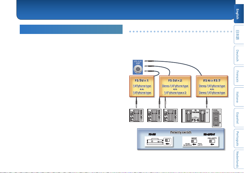
Assigning functions to an external pedal
You can connect a footswitch (FS-5U, FS-6 or FS-7, sold separately)
to the CTL 2, 3/EXP jack, and use it to tap-input the tempo or to
switch memories.
The settings for this are in the“CTL FUNCTION,” found in the menu
(p. 10).
FS-5U FS-6/FS-7
CTL 3 CTL 2 CTL 3 CTL 2
CTL 3
CTL 2
CTL 2
FS-5U × 2
FS-5U FS-6/FS-7

Various Settings (Menu)
10
Parameter List
ON/OFF FUNCTION
These parameters specify the function of the [ON/OFF]
switch.
Parameter Value
FUNCTION
Sets the function of the switch.
5ON/OFF: Eect on/o
5MEMORY: Switches between
memories.
5MEM/ON: Switches between
memories. Hold down the switch to
switch to the eect on/o function.
Parameter Value
PARAM
Sets how the switch operates.
ON/OFF:
5TOGGLE: Switches the eect with each
press of the switch.
5MOMENT: Switches the eect only
while the switch is pressed.
MEMORY:
5INC: Increments the memory number
according to the MEMORY EXTENT
MIN/MAX setting.
5DEC: Decrements the memory number
according to the MEMORY EXTENT
MIN/MAX setting.
51–128: Switches to the specied
memory.
PREF
5MEMORY: Changes the settings per
memory.
5SYSTEM: Makes the settings the same
for all memories.
CTL FUNCTION
Use this to congure the functions of the
[MEMORY/CTL 1] switch and the footswitch connected
to the CTL 2, 3/EXP jack.

Various Settings (Menu)
11
Parameter Value
FUNCTION
Selects which function the switch controls,
as follows.
MEMORY: Selects the memory.
S.HOLD: Holds (sustains) the sound. This
makes the sound you play sustain.
PITCH: Applies a pitch-bend eect.
TAP: Tap tempo. You can set the tempo
according to the beat (intervals) at which
you press the footswitch.
TEMPO: Edits the tempo in BPM (beats
per minute).
ON/OFF: Eect on/o
PARAM 1
Congures the eect.
MEMORY: INC, DEC, 1–128
PITCH:
5-24–0–+24: Sets how much the pitch
changes in semitones.
TEMPO:
540–250: Sets the BPM value.
PARAM 2
Adjusts the eect.
PITCH:
50–100: Adjusts the time over which the
pitch changes.
Parameter Value
SW MODE
Sets how the switch operates.
5TOGGLE: Switches the eect with each
press of the switch.
5MOMENT: Switches the eect only
while the switch is pressed.
* This cannot be selected when FUNCTION is set
to “MEMORY” or “TAP.”
PREF
5MEMORY: Changes the settings per
memory.
5SYSTEM: Makes the settings the same
for all memories.
MEMO
Hold the [MEMORY/CTL 1] switch down to switch between settings
for two functions.
MEM=/HLD: Increment memory, sound hold
MEM=/PT: Increment memory, pitch bend
MEM=/TAP: Increment memory, tap tempo
MEM=/TMP: Increment memory, tempo (BPM)
MEM=/ON: Increment memory, eect on/o
MEM?/HLD: Decrement memory, sound hold
MEM?/PT: Decrement memory, pitch bend
MEM?/TAP: Decrement memory, tap tempo
MEM?/TMP: Decrement memory, tempo (BPM)
MEM?/ON: Decrement memory, eect on/o

Various Settings (Menu)
12
EXP PDL FUNCTION
Species the function of the expression pedal connected
to the CTL 2, 3/EXP jack.
Parameter Value
FUNCTION
Select the function of the pedal.
OFF, TONE, RESONANCE, PITCH, RATE,
TEMPO, DEPTH, E.LEVEL, D.LEVEL,
MULTI
5OFF: No operation.
5MULTI: You can control the settings
for knobs [1], [2], [3], [D. LEVEL] and [E.
LEVEL] with the expression pedal.
* The functions assigned to knobs [1], [2] and [3]
dier for each memory.
* “MULTI” is shown only if PREF is set to
“MEMORY.”
MIN Set the minimum (MIN) value
MAX Set the maximum (MAX) value
PREF
5MEMORY: Changes the settings per
memory.
5SYSTEM: Makes the settings the same
for all memories.
Here's how to set the multi settings.
1. Set the minimum (MIN) value using the [1], [2], [3], [D.
LEVEL] and [E. LEVEL] knobs.
2. Press the [MEMORY] knob.
3. Set the maximum (MAX) value using the [1], [2], [3], [D.
LEVEL] and [E. LEVEL] knobs.
4. Press the [MEMORY] knob.
SEND/RETURN
Sets the function for the SEND/RETURN jack.
Parameter Value
SEND/RETURN
5SEND: Selects the signal that is output
to the SEND jack.
DIRECT, EFFECT
* When this is set to DIRECT, you can adjust the
RETURN volume using the [D. LEVEL] knob.
When this is set to EFFECT, you can make
adjustments using the [E. LEVEL] knob.
5PREFERENCE: If you want to change
the SEND settings per memory, set this
to “MEMORY.”
MEMORY, SYSTEM

Various Settings (Menu)
13
SYSTEM
Parameter Value
MODE
Switches to settings that are suitable for a
guitar or a bass.
GUITAR, BASS
EFFECT OUTPUT
You can switch to settings more
appropriate for playback devices. Use
the “AMP” setting for guitar/bass amps,
and the “LINE” setting for equipment like
monitor speakers.
AMP, LINE
DISPLAY CONTRAST Adjusts the contrast of the display.
1–16
MEMORY EXT MIN Sets the minimum (MIN) and maximum
(MAX) values for selectable memories.
1–128
* You can select all memories with [MEMORY]
knob.
MEMORY EXT MAX
EXP PDL HOLD
Species whether or not the operational
status of the EXP PEDAL’s FUNCTION is
carried over when memories are switched.
ON, OFF
* You can adjust this if the EXP PEDAL’s PREF
parameter is set to MEMORY.
MIDI
Parameter Value
RX CH
Species the MIDI receive channel.
If this is “OFF,” MIDI messages are not
received.
1–16, OFF
TX CH
Species the MIDI transmit channel.
If this is “OFF,” MIDI messages are not
transmitted. When set to “Rx,” the unit
transmits on the same channel as the
RX CH.
1–16, Rx, OFF
PC IN
Sets whether program change messages
are received (ON) or not (OFF).
ON, OFF
PC OUT
Species whether program change
messages are transmitted (ON) or not
(OFF).
ON, OFF
CC IN
Species whether control change
messages are received (ON) or not (OFF).
This unit can use CC messages it receives
to control the same operations as a knob
or footswitch via MIDI.
ON, OFF

Various Settings (Menu)
14
Parameter Value
CC OUT
Species whether control change
messages are transmitted (ON) or not
(OFF).
ON, OFF
PARAM1 CC
Species the controller number
corresponding to each controller.
OFF, #1–31, #64–95
PARAM2 CC
PARAM3 CC
D. LEVEL CC
E. LEVEL CC
ON/OFF SW CC
CTL1 CC
CTL2 CC
CTL3 CC
EXP CC
EFFECT CC
SYNC
Species the tempo clock to which this
unit synchronizes.
INTERNAL: Synchronizes to the internal
tempo.
AUTO: Normally synchronizes to the
internal tempo, but if a MIDI clock is
received via the MIDI IN connector, the
tempo synchronizes to the MIDI clock.
If you’re using the SY-200 as a remote
device, choose “AUTO.”
CLOCK OUT Sets whether to output the internal clock.
ON, OFF
Parameter Value
MIDI THRU
Species whether MIDI messages received
at the MIDI IN connector are retransmitted
as-is from the MIDI OUT connector (ON) or
are not retransmitted (OFF).
ON, OFF
MIDI PC MAP
Use the program change map to customize which
memories on the SY-200 correspond to which program
change messages sent from an external MIDI device,
switching to the memory in question.
Parameter Value
PC#1–PC#128
OFF, 1–128: Sets the memory number
(1–128) that corresponds to the program
number.
If this is “OFF,” the eect turns o.
15
Restoring the Factory Settings
(Factory Reset)
Here’s how to restore the SY-200 to its factory defaults.
You can also restore just the system settings or part of
the memories. Select the range to initialize using the
“FROM” and “TO” parameters.
1. Press the [MENU] button.
The unit enters MENU mode.
2. Select “FACTORY RESET.”
3. Turn knobs [1] and [3] to edit the range you
wish to initialize.
Parameter Explanation
FROM, TO SYSTEM: System parameter settings
001–128: Memory settings
4. Use the [MEMORY] knob to select“OK,” and
then press the [MEMORY] knob.
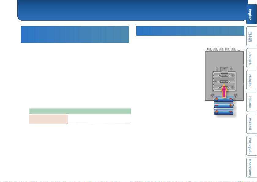
Changing the Batteries
Insert the batteries facing the correct way, as shown in
the illustration.
* Batteries should always be installed or
replaced before connecting any other
devices. This way, you can prevent
malfunction and damage.
* If operating this unit on batteries,
please use alkaline batteries.
* Even if batteries are installed, the
unit will turn o if you connect or
disconnect the power cord from the
AC outlet while the unit is turned on,
or if you connect or disconnect the
AC adaptor from the unit. When this
occurs, unsaved data may be lost. You
must turn o the power before you
connect or disconnect the power cord
or AC adaptor.
* When turning the unit over, be careful so as to protect the buttons and
knobs from damage. Also, handle the unit carefully; do not drop it.
* If you handle batteries improperly, you risk explosion and uid leakage.
Make sure that you carefully observe all of the items related to batteries
that are listed in“USING THE UNIT SAFELY” and “IMPORTANT NOTES”
(leaet “USING THE UNIT SAFELY” and the Owner’s Manual).
* “BATTERY LOW”will appear on the display if the batteries are low.
Replace them with new ones.
Appendix
Appendix
16
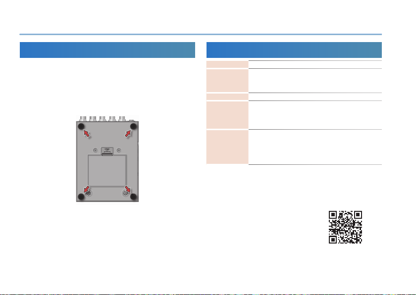
Attaching the Rubber Feet
You can attach the rubber feet (included) if necessary.
Attach them in the locations shown in the illustration.
* When turning the unit over, be careful so as to protect the buttons and
knobs from damage. Also, handle the unit carefully; do not drop it.
* Using the unit without rubber feet may damage the oor.
Main Specications
Power Supply Alkaline battery (AA, LR6) x 3, AC adaptor (sold separately)
Dimensions
101 (W) x 138 (D) x 63 (H) mm / 4 (W) x 5-7/16 (D) x 2-1/2 (H)
inches (excluding rubber feet)
101 (W) x 138 (D) x 65 (H) mm / 4 (W) x 5-7/16 (D) x 2-9/16 (H)
inches (including rubber foot)
Weight 700 g / 1 lb 9 oz (including batteries)
Accessories
Owner’s Manual
Leaet“USING THE UNIT SAFELY”
Alkaline battery (AA, LR6) x 3
Rubber foot x 4
Options (sold
separately)
AC adaptor: PSA-S series
Footswitch: FS-5U
Dual footswitch: FS-6, FS-7
Expression pedal: FV-500H, FV-500L, EV-30, Roland EV-5
MIDI/TRS connecting cable: BMIDI-5-35
* 0 dBu = 0.775 Vrms
* This document explains the specications of the product at the time
that the document was issued. For the latest information, refer to the
Roland website.
https://roland.cm/sy-200_spec
17
CAUTION
Keep small items out of the reach of children
To prevent accidental ingestion of the parts
listed below, always keep them out of the reach
of small children.
• Accessories
Rubber foot x 4 (p. 16)
Handle the ground terminal carefully
If you remove the screw from the ground
terminal, be sure to replace it; don’t leave it
lying around where it could accidentally be
swallowed by small children. When refastening
the screw, make that it is rmly fastened, so it
won’t come loose.
Repairs and Data
• Before sending the unit away for repairs, be sure to write
down the needed information. Although we will do our
utmost to preserve the data stored in your unit when
we carry out repairs, in some cases, such as when the
memory section is physically damaged, restoration of
the stored content may be impossible. Roland assumes
no liability concerning the restoration of any stored
content that has been lost.
Additional Precautions
• Any data stored within the unit can be lost as the result
of equipment failure, incorrect operation, etc. To protect
yourself against the irretrievable loss of data, try to
make a habit of writing down the needed information.
• Roland assumes no liability concerning the restoration
of any stored content that has been lost.
• Never strike or apply strong pressure to the display.
• When disposing of the packing carton or cushioning
material in which this unit was packed, you must observe
the waste disposal regulations that apply to your locality.
• Do not use connection cables that contain a built-in
resistor.
USING THE UNIT SAFELY/IMPORTANT NOTES

USING THE UNIT SAFELY/IMPORTANT NOTES
18
Intellectual Property Right
• This product includes third party open source software.
Copyright (c) 2009-2017 ARM Limited. All rights reserved.
Licensed under the Apache License, Version 2.0 (the
“License”);
You may obtain a copy of the License at
http://www.apache.org/licenses/LICENSE-2.0
• Roland and BOSS are either registered trademarks or
trademarks of Roland Corporation in the United States
and/or other countries.
• Company names and product names appearing in this
document are registered trademarks or trademarks of
their respective owners.
Table of contents
Other BOSSCO Synthesizer manuals


