Bosslan BOSSGSM-LED-HP27D User manual

1
Triband signal repeater
User Manual

2
CATALOGUE
C h ap t e r 1 Sa f e ty Wa r ni n g … … … . …… … … … … … … … … … … … … …… … . . 3
C h a p t e r 2 Su m m a r y … … … … … … … . … … … … … … … … … … … … … … … … . 4
C ha p t er 3 S pe c s a n d f e at u r es … …… … … …… … … … …… … … … … … … .. . 4
3 . 1 P r o d u c t De s c r i p t i o n s … … … … … … … … … … … … … … … … … … … … … … 4
3.2 Features……………………………………………………………………….4
3 . 3 S y s t e m d i a g r a m … … … … … … … … … … … … … … … … … … … … … … … … 5
3 . 4 A p p e a r a n c e D i a g r a m … … … … … … … … … … … … … … … … … . . . … … … … 5
3.5 Ports………………………………………………………………...…………5
C ha p t e r 4 I n s t a l l a t io n … … … …… … … … … … … … … . . … … … … … … … … … 6
4 . 1 I n s t a l l a t i o n r e q u i r e m e n t s … … … … … … … … … … … … … … . . … … … … … . . 7
4 . 2 I n s t a l l a t i o n … … … … … … … … … … … … … … … … … … … … . . … … … … … . . 7
4 . 3 C o n n e c t i o n … … … … … … … … … .. . … … … … … … … . … … … . … … … … … .. 7
C h a p t e r 5 Re p e a t e r s e t t i n g … … … … … … … … … … … . … … … . … … … … … . 8
5 . 1 P o w e r s u p pl y c o n n e c t i o n … … … … … … . … … . . … … … … … … … … … … … 8
5 . 2 P e r f o r m a n c e se t t i n g … … … … … …… … … … … … … … … … . … … … … … .. 9
Cha pt er 6 Pr o du ct M ai nt en a nc e ……… … … ... .. . .. .. .. .. . .. .. .. .. … … .. ……… 1 0
6 . 1 O pe r a t i on an d m a in t e n a n c e … … . . . … … …… … … … … … … … . …… … … 1 0
6 .2 E m e r g e n c y de a l i n g … … … … … … … … … … … … … … … … … … . … … … . . 10
6. 3 M ai n t a in i n g d i re c t i o n s … … … … … … …… … … … … … … … …… … …… . 11

3
Chapter 1 Safety Warning
Users must follow the below principles:
1Repeater should follow system requirement of communication
equipment, assure good groundings and lightning protection.
2 The power supply voltage of repeater should meet the standards of
security requirement; any repeater-operator can operate only after
cutting power in advance. Only the professional can operate
electrified.
3 Do not dismantle machine, maintain or displace accessories by
yourself, because in this way, the equipment may be damaged or
even get an electric shock.
4 Do not open the repeater; touch the module of repeater, even not to
open the cover of module to touch the electronic component, the components
will be damaged due to electrostatic
5 Please keep away from heating-equipment, because the repeater will
dissipate heat when working. And do not cover repeater with
anything that influences heat-dissipation.

4
Chapter 2 Summary
In mobile communication, it is inevitable that macro-cell coverage cannot cover
weak or dead zones; to use repeater is a good choice in these areas. Dual wide band
repeaters mainly applied in covering small blind and weak zones. Such as VIP rooms,
offices, houses, restaurants, apartments, parking lots, etc.
3.1 Application
Application
Quad band, five band repeaters enhance consumer satisfaction greatly with its
integrated design, compact size, easy engineering and rapid installation and debugging.
Chapter 3 Specs and features
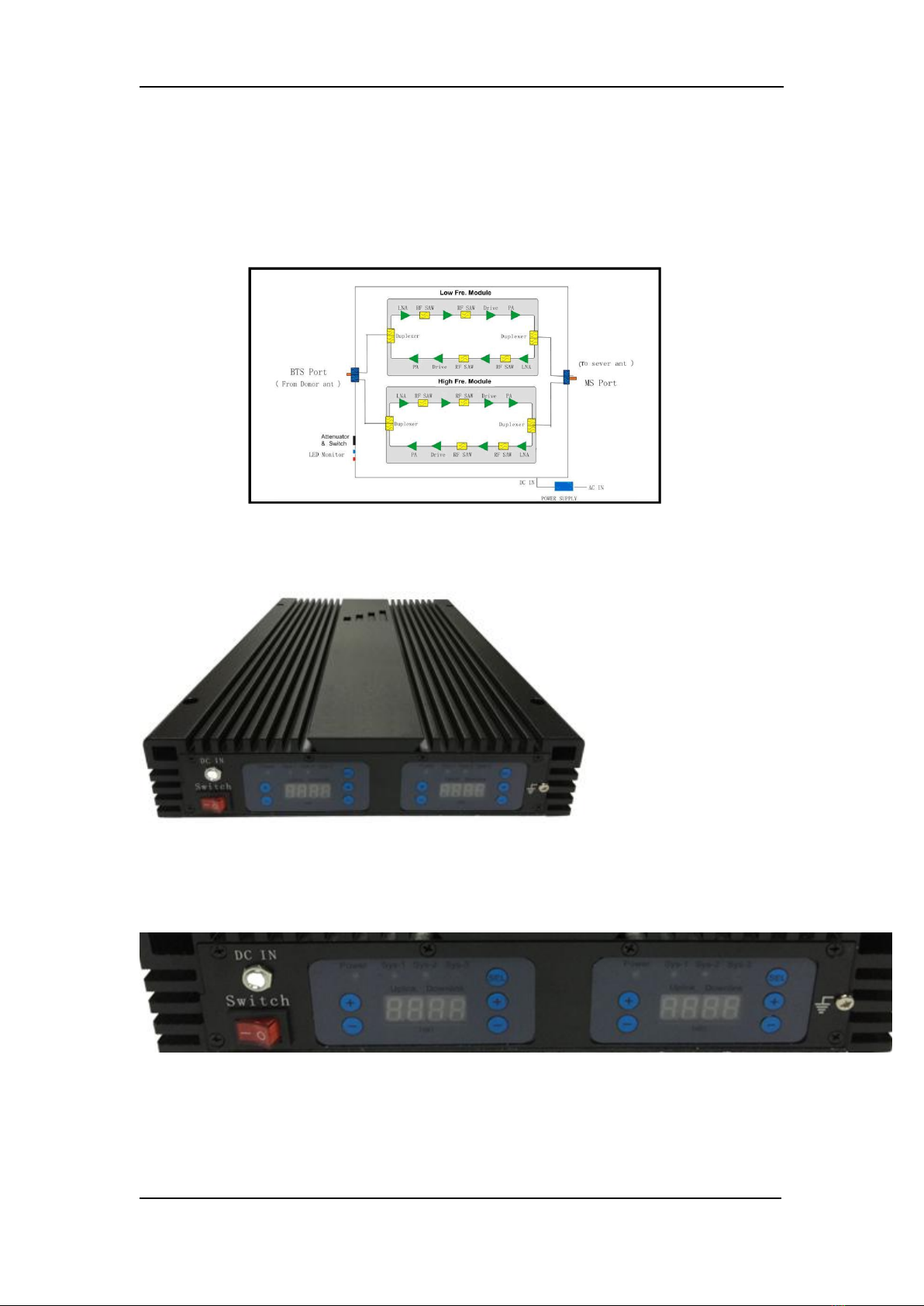
3.1 Product Descriptions
(1) In Terminal: N Female
(2) LED: To monitor the status of power
on/off and normal operation
(3) Power Supply Terminal: External
(4) Power supply (Operating voltage: 9V/ 5A)
3.2 Features
Compact design and light weight, cost effectiveness
LED indication for operation status.
Wide band function to work on any network combined by GSM,DCS,WCDMA ,LTE support.
Low power consumption, Low interference.
Applicable to In-Building with medium or small size with Maximum coverage up to
5
500-3000 Square meters
ALC to limit output power at specified power level and ensure stable coverage effect.
AGC function by 1dB/step from 1-31dB Gain range.
3.3 System diagram
3.4 Appearance Diagram
3.5 Ports(BTS for outdoor, MS for indoor.)
Chapter 4 Installation

6
4.1 Installation requirements
Quad band, five band repeaters are mainly applied to indoor coverage solution . After
connection of equipment and antenna, the distance of them should be keep as far away
as possible, it’s better that there is a wall as the obstruct between them( far than 15
meters).
Position selection
Install in the place that is not easy to be reached by irrelevant people.
Install at the place that is convenient for power supply and cabling
Avoid heat source and moist environment
Power supply requirement
AC power supply of AC 95~264V
Installation tools and accessories
Series
item
specification
Quantity
Remarks
1
Expanding plug
M7
4
Accessories
2
Tapping screw
M6*40
4
Accessories
3
Spinner
1
4
Waterproof tape
1
5
Ruler
1
measurement and installation of hole
6
Percussion drill
1
drilling on wall
7
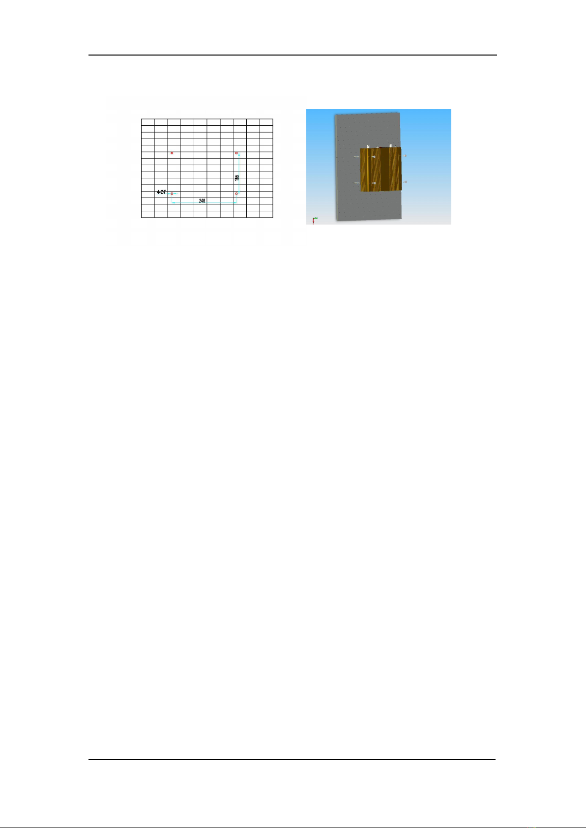
4.2 Installation
Installation step 1 Installation step 2
Installation Steps:
1: Use percussion drill to make four Φ7 holes on the wall according to above
hole diagram, fasten the Expanding plug onto the wall.
2: Screw up repeater to the wall.
4.3 Connection
Connection of RF cable
BTS port connect with the outdoor antenna , put antenna on the place where
there is strong signal, then connect to MS port of equipment and assure good
connection.
Grounding connection
Use earth wire to link the repeater grounding port with building grounding system.
Power resistance must be less than 10 Ohm
Power supply connection
Please use three-pin plug to assure good grounding
Chapter 5 Repeater setting
Please check whether the connection of RF cable is correct (donor antenna connected

8
to input port, service antenna connected to output port), and whether every port is stable.
After affirmation, please go along the followings:
5.1 Power supply connection
After power supply connection, check ALARM and POWER indicators first.
Status and definition of POWER indicators:
Status and definition of Sys-1/Sys-2 indicators:
5.2 Performance setting
Status
Definition
green
Normal
off
DC power problem
Status
Definition of ALARM
Green
Meaning: working well
Red
Meaning: self oscillation, strong input signals
Attention: Please adjust LED Panel
Red
Meaning: overloading or self oscillation, strong input
signals
Red
Attention: input signal level is too high or the space of
donor antenna and service antenna is not enough. please
adjust the dB, If the red light still turning on that means
over accepting of donor antenna or strong interference,
then please adjust the place of donor antenna.

9
Curve chart of equipment working condition
Picture 3: Curve of output power, input signal and attenuation value
1/ POutput Power: output power 4/ Pinput Power -VATT:
2/ Pinput Power: input power input power- attenuation value
3/ VATT: attenuation value 5/ Pmax: output power rating
Downlink gain setting
As for the downlink working performance, “At the edge of green” is a good working
point. At this time, downlink output power and coverage effect are stable.
But from another point of view, we hope the equipment is as far as possible away
from overloading status of “red” (thus the equipment would hold higher interference
depression ability). So we try our best to set the equipment near “edge point” when
engineering.
Setting of “edge point”: (Switch on the power supply after connection with donor
antenna and coverage antenna, and observe ALARM indicator.)
Uplink gain setting
Uplink gain is set based on downlink gain..
Advantages:
1. Fast & easy Installation
POutput Power
Pmax
(Pinput Power-VATT)
Green: Linear
amplification
Red:
Overloading
Orange:stable
performance
Edge Point

10
The installation of a repeater is easy and simple. With its plug and play design, installation
simplicity, and operational user friendliness, these features appeal greatly to many
operators for the purpose of indoor coverage or for temporary coverage during network
optimization.
2.Smart Function, Intelligent mode setting
smart function called which can be activated via the front panel.
users can adjust gain and choose working band by LED panel, It is a simple, safe and
effective way.
When the repeater turn on, will show green.
can choose Sys-1,
or Sys-2.
for uplink, for downlink, add and subtract dB.
you can see accurate gain from this LED .
5.3 Auto Level Control
The 30dB ALC is used to maintain steady output power even when the donor source
signal fluctuates. Also when the ALC is activated>1-5dB, the LED indicator would be
lighted in RED, which means the Isolation may not be enough.
11
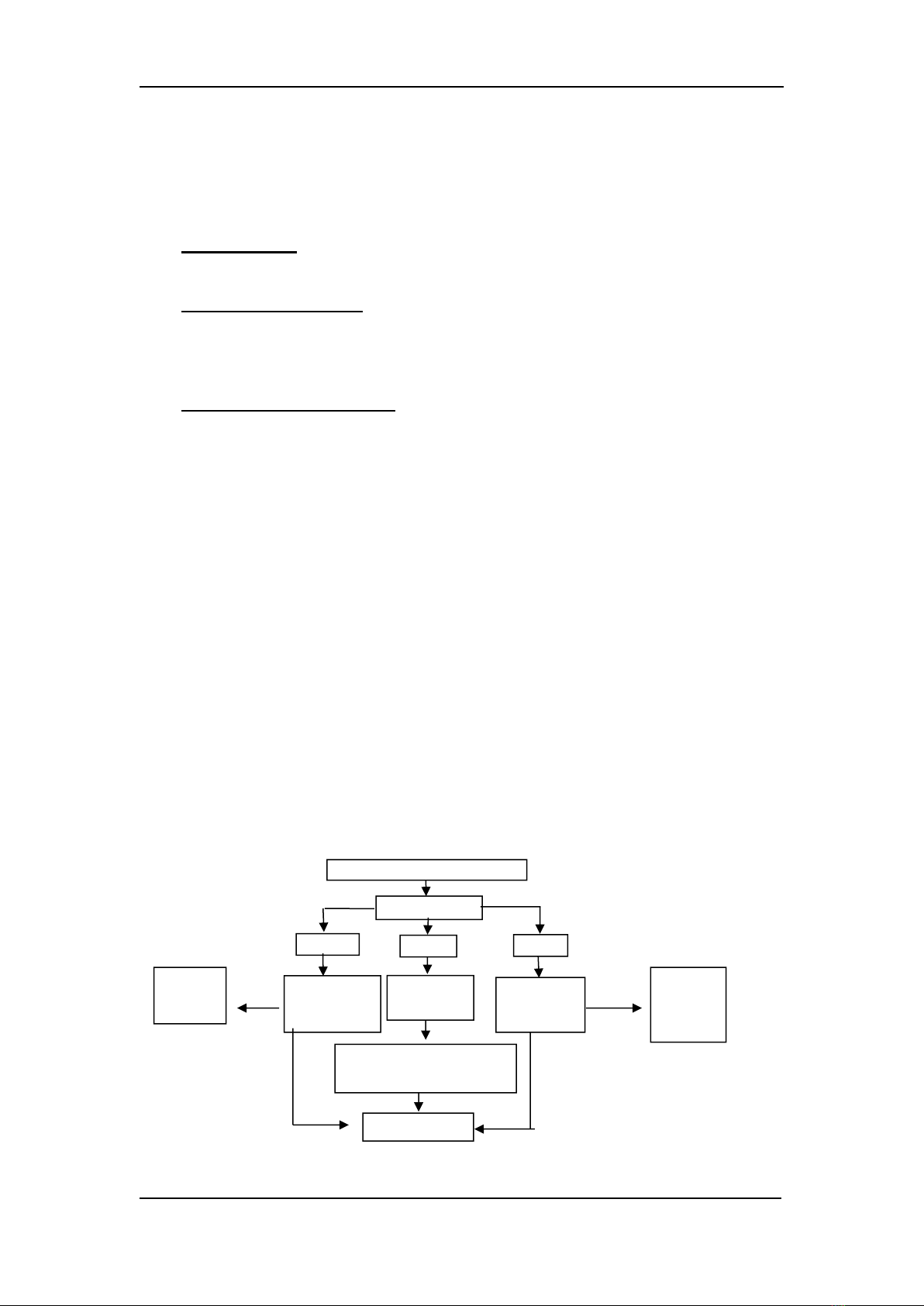
LED check
Green
Improve the
feeder
system
Strong interference near donor
antenna
Abnormal
Feeder system
inspection
Improve the
power supply
system
Red
Off
Isolation
inspection
Power supply
inspection
Abnormal performance
Abnormal
Abnormal
Abnormal
Chapter 6 Product Maintenance
6.1 Operation and maintenance
Power supply
Please make sure the voltage and frequency comply with the repeater requirement.
Component replacement
Please do not maintain or replace components by yourself, otherwise may get an
electric shock. Only the authorized professional can maintain and replace the
components.
Waterproof and moist proof
Please do not turn on or off the booster in moist environment when its door is
opened.
6.2 Emergency dealing
Switch off is recommended during following situations:
The power supply is not normal
Liquid flows into the equipment;
Working conditions is not normal, (overheating, abnormal smelling, abnormal sundries)
Closet damage
performance debasement
near to fire
flooding
6.3 Maintaining direction
Please check the repeater step by step according to below process, to find out the problem
with the repeater.
Contact supplier
Table of contents
Other Bosslan Repeater manuals

Popular Repeater manuals by other brands

AVM
AVM FRITZ DECT Repeater 100 Installation and operation guide

ADTRAN
ADTRAN T200 T1 HDSL4 Installation and maintenance practice

O2Line
O2Line TRIO2SYS 10020113 Installation and operating manual

Spectra
Spectra MX920 Operation manual

Dacom
Dacom GIR-2005 Installation & operation manual

Siemens
Siemens Gigaset Optical LAN Adapter Duo instruction manual


