Maintenance - Changing the Diaphragm
The Bosworth Company
5 Doc M-09-32-120115
Over time, the elastomer components of the pump (i.e., the diaphragm and valves) will fail. Diaphragms tend to
develop a hole or tear. If the diaphragm fails, the pump will continue to operate, but will be unable to create or
maintain a vacuum. Additionally, you will notice sap leaking from the diaphragm and out around the pump
guard. Your Guzzler pump ships with a spare diaphragm. Additional replacement diaphragms can be purchased
through your local maple sap equipment dealer and directly from our
website (www.thebosworthco.com). Note that the GE‐0401x and the GE‐
0501x pumps use the same size diaphragm.
When replacing the diaphragm, close aenon should be paid to the ori‐
entaon of various parts. The use of witness marks may be helpful during
the reassembly.
Remove pump body from aluminum
mounng plate.
Figure 4
1. Disconnect the power.
2. Turn the pump upside down so that it is resng on the pump guard
and motor. With a pencil, mark the side of the mounng plate
next to the pump inlet (the shorter of the two ports).
3. Remove the 10 screws holding the pump body to the aluminum
mounng plate. (Figure 4)
4. Remove the pump body to expose the diaphragm screw aaching
the plasc “buon” (a plasc support plate) to the diaphragm.
5. Remove the sloed head screw, washer, buon and diaphragm
from the aluminum connecng rod. (Figure 5)
6. Ensure the top buon (rounded edge side toward diaphragm) and
stainless steel washer are properly seated on the connecng rod,
and then place the new diaphragm onto the top buon. Reinstall
the boom buon (rounded edge side toward diaphragm) and
stainless steel washer onto the diaphragm and secure all with the
diaphragm screw. Note: Be sure to place the diaphragm on the
connecng rod so that the ridge running along the diaphragm’s
circumference is facing toward you. (The other side of the dia‐
phragm’s outer edge is flat.) Be sure the screw is ght. We recom‐
mend using blue Locte on the screw to help ensure it does not
come loose during pump operaon.
7. Place the pump body up against the diaphragm and align it with
the holes on the Intermediate Ring and Mounng Plate. Be sure
that the diaphragm’s outer lip sits in the groove running around
the circumference of the pump body. (Figure 6) (Note: Ensure
the pump body is installed in the correct orientaon, with the
inlet next to the mounng plate witness mark made in Step 2.)
8. Fasten the pump body to the mounng plate using the 10 screws
and nuts. Start all screws and nuts before ghtening them
down. Tighten to a maximum of 30 in‐lbs of torque. Tighten
screws evenly (crisscross paern). Do not completely ghten
screws unl everything is aligned.
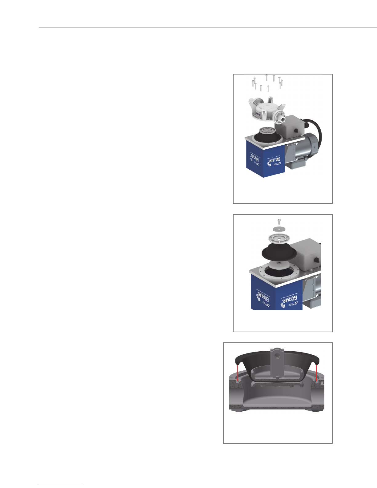
Outer lip of diaphragm fits into groove on
pump body.
Figure 6
Remove diaphragm screw.
Figure 5


