Bosworth Guzzler GE-0404D User manual
Doc M-PR-09-36.120318
..
G®24VDCDP
for use as Maple Sap Vacuum pumps
Copyright©2018 The Bosworth Company
O’M...
GE‐0404D
GE‐0404N
GE‐0504D
GE‐0504N
1 Doc M-09-36-092518
The Bosworth Company
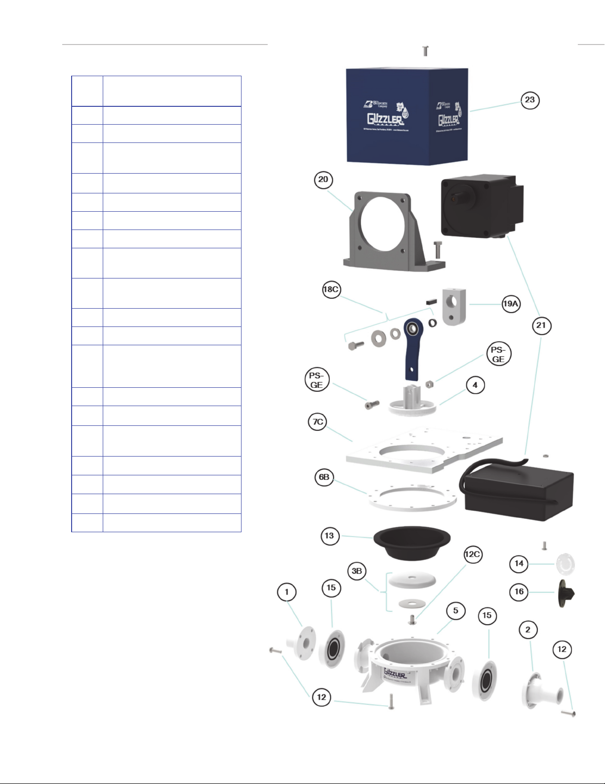
Item
#
Part Name
1InletFlange
2OutletFlange
3BBoomBuon&StainlessSteel
Washer
4Clevis
5Body
7CMotorMounngPlate
12MiscellaneousHardware(10‐24
Screws&Nuts)
12CTH1/4‐20x1/2(1)Diaphragm
Screw
13Diaphragm
14FlapperValves
15UmbrellaValves(Umbrella
valves(2),ValveStops(2),O‐
rings(4),Screws&Nuts)
16DuckbillValves
18CConnecngRodBolt&Spacer
19ACrankArm(18mmwith1/4‐20
SetScrews(2)
20MotorMounngBracket
2124VDCMotor&Controller
23PumpGuard
PS‐GEPinSetforGEpumps
6BIntermediateRing
Note:
GE‐0404Nispictured.
GE‐0404Dhasgraybody,flanges
Guzzler GE-0404xPump Exploded View
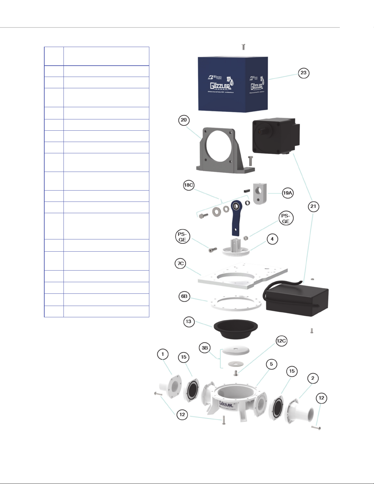
Guzzler GE-0504xPump - Exploded View
2
The Bosworth Company
Doc M-09-36-092518
Item
#
Part Name
1InletFlange
2OutletFlange
3BBoomBuon&StainlessSteel
Washer
4Clevis
5Body
6BIntermediateRing
7CMotorMounngPlate
12MiscellaneousHardware(10‐24
Screws&Nuts)
12CTH1/4‐20x1/2(1)Diaphragm
Screw
13Diaphragm
14FlapperValves
15UmbrellaValves(Umbrella
valves(2),ValveStops(2),O‐
rings(4),Screws&Nuts)
18CConnecngRodBolt&Spacer
19ACrankArm(18mm)with1/4‐20
SetScrews(2)
2124VDCMotor&Controller
23PumpGuard
PS‐GEPinSetforGEpumps
20MotorMounngBracket
Note:
GE‐0504Nispictured
GE‐0504Dhasgraybody,flangesand
buons.
Your Guzzler pump ships fully assembled and ready to operate
(Figure 1). The pump should be protected from the weather. If
it is placed in an enclosure, be sure to allow adequate airflow
around the motor for cooling.
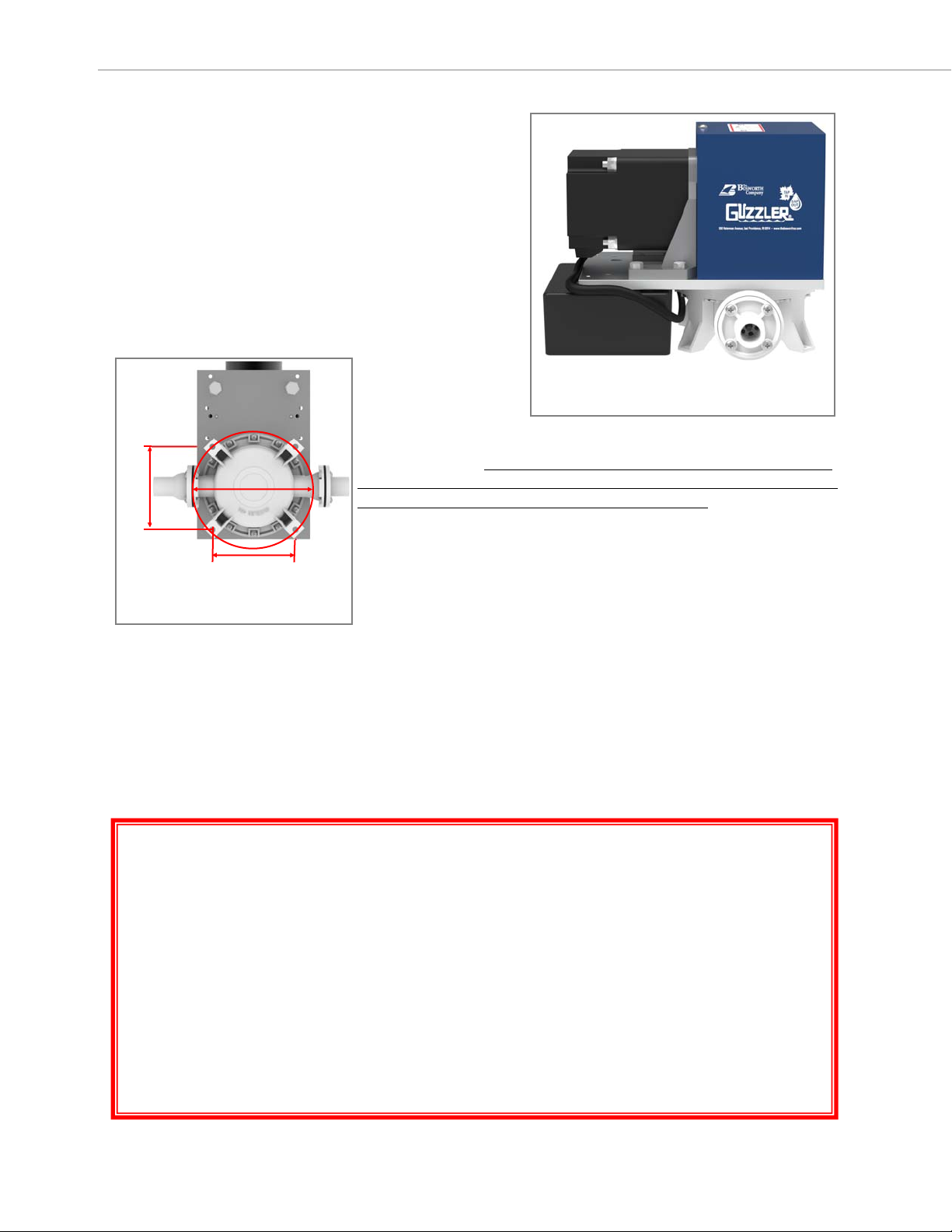
Prior to operation, the pump should be securely fastened to a
mounting surface. The four pump feet have mounting holes
that can accommodate a 1/4 in (6.4 mm) diameter bolt or
screw. The holes are arranged on a square, 4‐5/16 in (109.5
mm) on a side, inscribed on a bolt circle of diameter 6‐1/8 in
(155.6 mm). (Figure 2) We recommend countersinking holes on
the bottom of a mounting surface and inserting mounting bolts
up through those holes and through the pump feet. Secure the
end of the bolt with a nut.
You can test the pump’s operation by connecting the motor leads to a 24
VDC power supply. Be sure to connect the positive (white wire) lead from
the motor to the positive terminal on the battery/power supply; the nega-
tive (black wire) motor lead, to the negative terminal. Incorrectly connect‐
ing your pump will damage the motor controller and void your warranty.
Your Guzzler pump features an efficient 100 Watt (1/8 Hp) 24 VDC power.
Connecng your pump to two 60 amp‐hour 12VDC deep‐discharge baeries
wired in series should provide 20‐24 hours of pump operaon before requir‐
ing recharging.
Once the pump is connected, turn it on and carefully place your hand over
the inlet port (the shorter of the two pump ports) of the pump. You will feel the pump sucking your hand toward
the port. Take your hand away and place it over the outlet port of the pump. You will feel the pump’s exhaust
pushing your hand away from the port. When you can feel the vacuum created at the inlet port and the positive
exhaust pressure generated at the outlet port, the pump is operating properly.
Your Guzzler pump has a range of different inlet and outlet ports available to accommodate a range of different
connections to your sap lines and collection tank tubing. We recommend the use of Quick Connect Couplers so
that the pump can be easily disconnected from and reconnected to your lines.
NEVER OPERATE YOUR GUZZLER PUMP WITHOUT THE PUMP GUARD PROPERLY IN-
STALLED ON THE PUMP.
NEVER REACH INSIDE THE PUMP OR INSERT ANY OBJECTS INTO THE PUMP WHILE THE
PUMP IS OPERATING. SERIOUS INJURY OR DAMAGE TO THE PUMP WILL RESULT.
ALWAYS CONNECT THE PUMP TO A 24 VDC POWER SOURCE USING PROPERLY INSULATED
CONNECTORS. OPERATING THE PUMP WITHOUT PROPER ELECTRICAL CONNECTIONS
CAN CREATE A SERIOUS RISK OF ELECTRICAL SHOCK.
CONNECT THE POSITIVE (WHITE WIRE) PUMP LEAD TO THE POSITIVE TERMINAL OF THE
24 VDC POWER SUPPLY; THE NEGATIVE (BLACK WIRE) PUMP LEAD TO THE NEGATIVE
TERMINAL OF THE POWER SUPPLY. CONNECTING THESE TERMINALS INCORRECTLY
WILL DAMAGE THE PUMP MOTOR CONTROLLER AND VOID THE PUMP WARRANTY.
Guzzler GE-0404x/ -0504xPump Installation & Safety Information
The Bosworth Company
3 Doc M-09-36-032019
IMPORTANT SAFETY INFORMATION
Mounng holes on pump feet.
Figure 2
4-5/16 in
4-5/16 in
6-1/8 in
Figure 1
Pump can be securely mounted using mounng holes on
pump feet.
Pump Installation and Operating Information
4
The Bosworth Company
Doc M-09-36-092518
Your Guzzler Pump is capable of developing 22 in. of Hg vacuum (0.7 bar), but it is a low‐cfm (cubic feet of air per
minute) pump. This means that even very small leaks can prevent the pump from delivering its rated vacuum.
Maintain your tap lines to keep your system tight and address problems that can cause vacuum leaks.
It is best to install your Guzzler at or above collection tank level to avoid shortening diaphragm life. This will re‐
duce the output pressure on the diaphragm, thus reducing mechanical stress on the diaphragm.
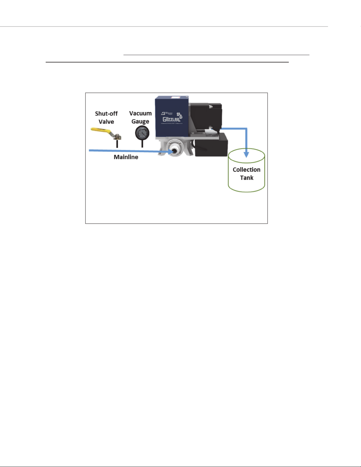
When installing your Guzzler Pump, we recommend that you install a shut‐offvalve and a vacuum gauge – in
that sequence – “in front of” the pump; i.e., just before your connecon to the pump’s inlet port. (Figure 3)
If you experience a loss of vacuum in your system – as registered in the gauge near the pump – slowly turn the
shut‐offvalve to isolate the pump from your mainline. DO NOT SHUT THE VALVE SUDDENLY, AS PUMP DAMAGE
MAY RESULT. If the gauge begins to return to normal operang vacuum, then the pump is working properly and
the source of the leak is somewhere in your sap lines or taps. If, on the other hand, the pump fails to recover
normal vacuum, then the pump is the source of the problem, and you should inspect the pump diaphragm and/
or valves for any holes or tears. In the case of the valves, check for any material that may have entered the
pump and lodged in the valve body, prevenng the valve from proper opening and closing.
The motor’s surface temperature may exceed 160°F (70°C). Ensure that the motor is protected from the ele‐
ments, but that it also has adequate airflow during operation to prevent overheating.
If there is a risk of freezing conditions, we recommend that you disconnect the pump from your sap lines when
the pump is not running and drain any excess sap from the pump. Sap can freeze within the pump bodies or
lines. If this happens and the pump is turned on, it will result in damage to various pump components, including
pump bodies, valves and diaphragms. We recommend flushing the pump (i.e., letting it pull a full volume of wa‐
ter) and then draining any remaining water from the pump to help prevent freezing.
To shut the pump down and disconnect it from the mainline, first turn the pump off. Then, close the shut‐off
valve to isolate and maintain some vacuum in the mainline. Then disconnect the pump from the mainline, using
Quick Couplers if you have used these for your pump‐to‐mainline connection. Turn the pump back on briefly to
flush any remaining sap from it. Finally, tilt the pump to drain any remaining sap.
Schemac showing recommended shut‐offvalve and vacuum gauge installed on
inlet side of pump.
Figure 3

Maintenance - Changing the Diaphragm
The Bosworth Company
5 Doc M-09-36-092518
Over time, the elastomer components of the pump (i.e., the diaphragm and valves) will fail. Diaphragms tend to
develop a hole or tear. If the diaphragm fails, the pump will continue to operate, but will be unable to create or
maintain a vacuum. Additionally, you will notice sap leaking from the dia-
phragm and out around the pump guard. Your Guzzler pump ships with a
spare diaphragm. Additional replacement diaphragms can be purchased
through your local maple sap equipment dealer and directly from our web-
site (www.thebosworthco.com). Note that the GE-0404x and the GE-0504x
pumps use the same size diaphragm.
When replacing the diaphragm, close aƩenƟon should be paid to the orien-
taƟon of various parts. The use of witness marks may be helpful during reas-
sembly.
1. Disconnect the power.
2. Turn the pump upside down so that it is resƟng on the pump guard
and motor. With a pencil, mark the side of the mounƟng plate
next to the pump inlet (the shorter of the two ports).
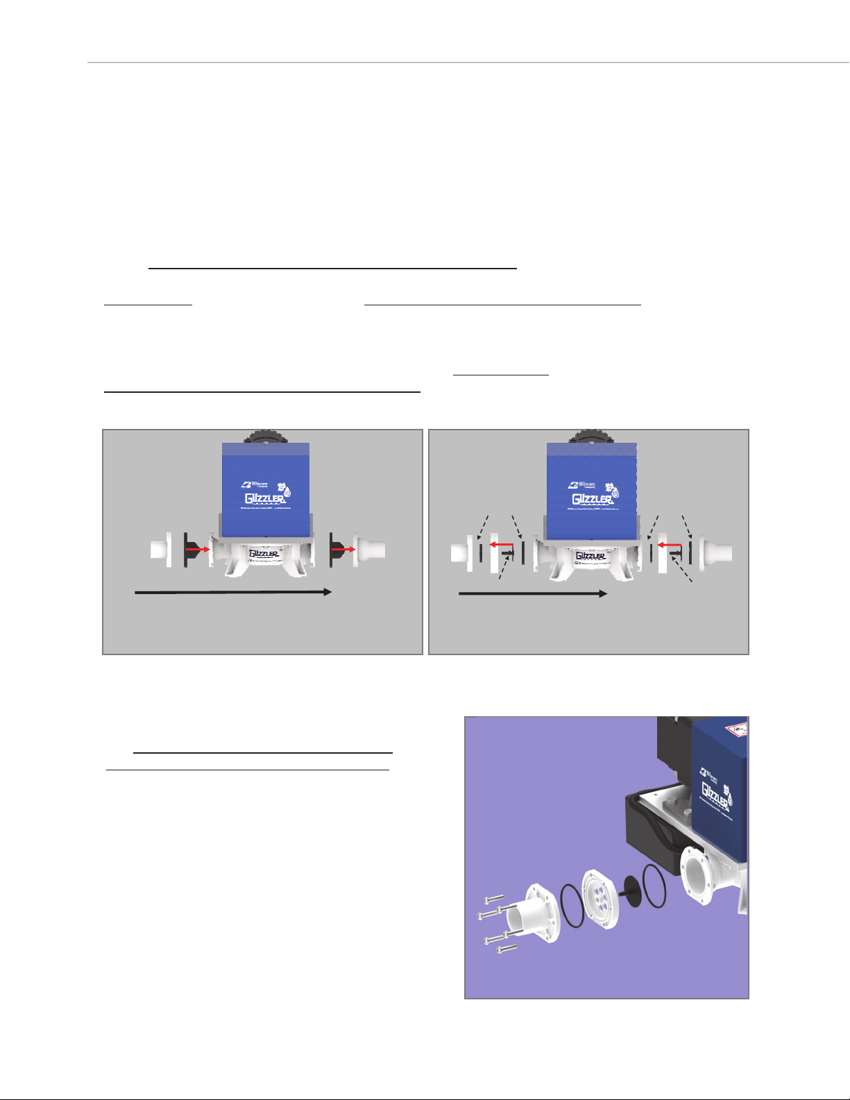
3. Remove the 10 screws holding the pump body to the aluminum
mounƟng plate. (Figure 4)
4. Remove the pump body to expose the diaphragm screw aƩaching
the plasƟc “buƩon” (a plasƟc support plate) to the diaphragm.
5. Remove the sloƩed head screw, washer, buƩon and diaphragm
from the aluminum connecƟng rod. (Figure 5)
6. Ensure the top buƩon (rounded edge side toward diaphragm) and
stainless steel washer are properly seated on the connecƟng rod,
and then place the new diaphragm onto the top buƩon. Reinstall
the boƩom buƩon (rounded edge side toward diaphragm) and
stainless steel washer onto the diaphragm and secure all with the
diaphragm screw. Note: Be sure to place the diaphragm on the
connecƟng rod so that the ridge running along the diaphragm’s
circumference is facing toward you. (The other side of the dia-
phragm’s outer edge is flat.) Be sure the screw is Ɵght. We recom-
mend using blue LocƟte on the screw to help ensure it does not
come loose during pump operaƟon.
7. Place the pump body up against the diaphragm and align it with
the holes on the Intermediate Ring and MounƟng Plate. Be sure
that the diaphragm’s outer lip sits in the groove running around
the circumference of the pump body. (Figure 6) (Note: Ensure
the pump body is installed in the correct orientaƟon, with the
inlet next to the mounƟng plate witness mark made in Step 2.)
8. Fasten the pump body to the mounƟng plate using the 10 screws
and nuts. Start all screws and nuts before Ɵghtening them
down. Tighten to a maximum of 30 in-lbs of torque. Tighten
screws evenly (crisscross paƩern). Do not completely Ɵghten
screws unƟl everything is aligned.
Outer lip of diaphragm fits into groove on
pump body.
Figure 6
Remove diaphragm screw.
Figure 5
Remove pump body from aluminum
mounƟng plate.
Figure 4

There are two valves in each Guzzler pump. One valve is located between the pump body and the inlet port; the
other, between the pump body and the outlet port. Your Guzzler pump may be equipped with either duckbill
valves or umbrella valves, depending on the pump options chosen.
The duckbill valve is shaped like a bird’s beak. When pressure is placed on the outside of the beak, it forces it to
close; when pressure is placed on the other end of the valve, it forces the beak to open so that fluid may pass.
(Figure 7A‐B) The duckbill valve on the GE‐0504x series pumps is slightly larger than that on the GE‐0404x
pumps.
The other kind of valve available for your pump is an
umbrella valve. The umbrella valve features a rubber
valve with a flat round disk held under tension against a
plastic plate (the “valve stop”) that contains a number
of holes or “pores”. (Figure 8)
When pressure is applied to one side of the valve stop,
it pushes the rubber disk away from the holes, like an
umbrella turning inside out. (Figure 9A‐B) When this
happens, fluid or air can pass through the holes. When
the pressure is reversed, the rubber disk is forced
against the holes, making a tight seal to prevent any
fluid or air from passing.
Either kind of valve can be fouled by material in the sap (e.g., wood shavings from taps, plastic shavings from tub‐
ing, etc.) that is too large to pass through the valve. When this happens, the diaphragm will be unable to develop
any vacuum. However, unlike the case of a diaphragm failure, valve malfunction will not result in any sap leaking
from the pump. If you were to disconnect the pump from your tap lines and perform the simple pump check
described on page 3, you would feel no vacuum pulling from the inlet port. To correct the problem the valve
should be removed, inspected and cleaned. Several of the steps involved in doing this are the same as the steps
required to change a valve. (Instructions on changing valves are provided on page 7.)
Maintenance - Changing Pump Valves
6
The Bosworth Company
Doc M-09-36-092518
GE‐0404x Duckbill valve (le: Closed; right: Open)
Figure 7A
GE‐0404x umbrella valve (le: Closed; right:
Open)
Figure 9A
GE‐0504x umbrella valve (le: Closed; right:
Open)
Figure 9B
Figure 8
Umbrella valve stop on GE‐
0404x pump. Four mounng
holes on periphery. Valve
stem retaining hole in cen‐
ter. Six valve “pores” to
admit air/fluid flow.
Umbrella valve. Stem
“snaps” into center valve
stop retaining hole.
GE‐0504x Duckbill valve (le: Closed; right: Open)
Figure 7B
Maintenance - Changing Pump Valves
The Bosworth Company
7 Doc M-09-36-092518
In the case of the umbrella valve, material may become lodged in the umbrella valve pores, preventing the rub-
ber umbrella valve from sealing tightly against the valve stop. The duckbill valve is generally better able to pass
fluid containing some debris or material. Nonetheless, it is also possible for material to become lodged in the
duckbill valve, preventing it from properly closing, resulting in loss of vacuum. If there is a loss of vacuum, in-
spect the valves and remove any foreign material that may be obstructing valve function.
Valves are typically replaced in pairs; i.e., the inlet and outlet valve of a given pump body are replaced at the
same Ɵme. The process of valve replacement is similar whether your pump contains duckbill valves or umbrella
valves. Care must be taken to install the valves in the proper orientaƟon.
Duckbill valves must be installed so that their pointed edge points in the direcƟon of fluid flow. (Figure 10A) On
the inlet side, the duckbill valve points into the pump body; on the outlet port, it points away from the pump
body.
Umbrella valves have a flat side and a side with a valve stem. Umbrella valves must be installed so that their
valve stems point in the opposite direcƟon to fluid flow. (Figure 10B) On the inlet side, the umbrella valve stem
points away from the pump body; on the outlet port, the stem points toward the pump body.
Changing Pump Valves
1. Disconnect the power.
2. Remove the screws holding the inlet flange to
the pump body. (Figure 11) (GE-0404x pump
has 4 screws; GE-0504x has 6 screws.) The
valve is located between this flange and the
pump body.
Pointed edge of duckbill valves point along the direcƟon of
fluid flow. (Example shown for GE-0404x pump)
Figure 10A
NOTE: When replacing a pair of pump valves, it is best
that only one valve is removed and replaced before
aƩempƟng to remove and replace the other valve.
Valve stem of umbrella valve points in opposite direcƟon of
fluid flow. (Example shown for GE-0404x pump.)
Figure 10B
Fluid flow Fluid flow
O-rings O-rings
Valve Stem
Valve Stem
Remove screws holding flange to pump body.
Figure 11

Maintenance - Changing Pump Valves
The Bosworth Company
Doc M-09-36-092518
8
3.Inspectthevalveforanytears.Removeanydirtormaterialthat
mayhavebecomelodgedinthevalve.Forumbrellavalves,in-
spectO-ringsinvalvestopforanysignofwearandreplaceas
necessary.Ensurethattheyarecorrectlyinstalledinthevalve
stopgrooves.(Figure 12)
4.Toreplaceanumbrellavalve,useapairofplierstograsptheflat
poronoftheoldumbrellavalveandpulltheenrevalve
throughthevalvestopcenterretaininghole.(Figure 13) Insert
thestemofthenewvalveintothevalvestopretainingholeso
thattheflatporonofthevalveisonthesamesideofthevalve
stopastheoldvalve.Useplierstograspthestemofthevalve
ontheothersideandpullitcompletelythroughunlitsnaps
intoplace.
5.Posionthenewvalve(ortheinspectedandcleanedold
valve)betweenthepumpbodyandthepumpinlet
flange,takingcaretoorientthevalveasshowninFigure
10onpage7.Fastenthepumpflangeand,forumbrella
valves,thevalvestoptothepumpbodyusingtheflange
screws.
6.Repeatsteps2-5,thismewiththeoutletsideofthe
pump.Be sure to install the outlet valve so it is oriented
as shown in Figure 10.
UmbrellavalvestopwithO-ringinstalledin
grooves.(ExampleshownforGE-0404x
pump.)
Figure 12
Useplierstoremoveoldumbrellavalvefromvalve
stop.(ExampleshownforGE-0404xpump.)
Figure 13
NOTE: IF THE VALVES ARE NOT ORIENTED CORRECTLY IN THE PUMP
FLANGES, THE PUMP WILL NOT FUNCTION PROPERLY AND COULD BE
DAMAGED UPON OPERATION.
Maintenance - Rod End Bearing Lubrication on Older Models
The Bosworth Company
9 Doc M-09-36-092518
Guzzler 24 VDC pumps that shipped prior to 10/1/2016 were equipped with a permanent magnet motor, as well
as a motor linkage that featured a rod end bearing with a grease fitting that required periodic lubrication. Guz-
zler 24 VDC pumps that shipped subsequent to 10/1/2016 were equipped with a connecting rod that featured a
self-lubricating bearing and need no lubrication.
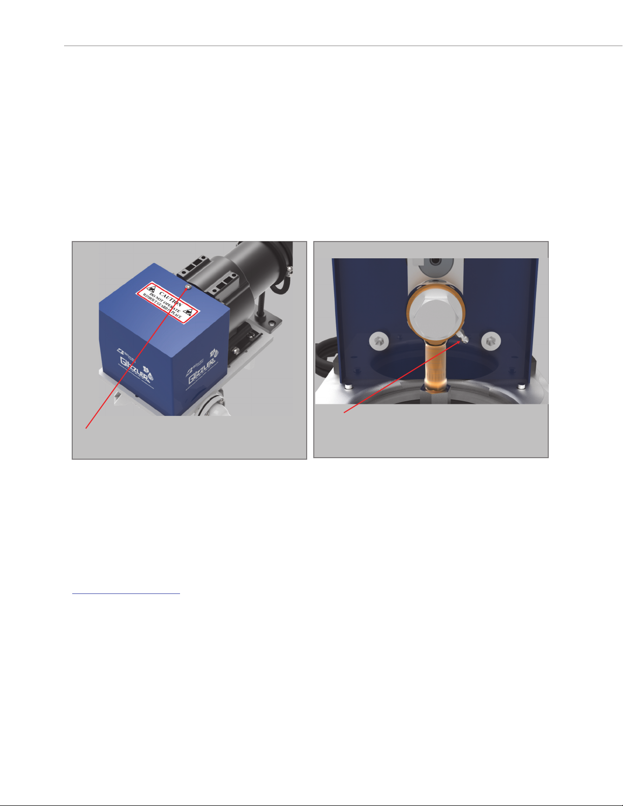
If your Guzzler has a grease fitting on its connecting rod, we recommend that the bearing be lubricated every 400
hours of operation or, more frequently, if operating conditions are such that the bearing begins to make a
squeaking noise. The fitting can be accessed by removing the screw that attaches the front of the pump guard to
the back of the guard plate. (Figure 14) Slide the front of the pump guard off the plate to reveal the grease fit-
ting. (Figure 15) The fitting can be lubricated with standard multi-purpose NLGI Grade 2 lithium grease.
Screw aƩaching front of pump guard to back of guard plate.
Figure 14
Grease fiƫng located on rod end bearing of Guzzler 24 VDC
pumps shipped prior to 10/1/2016.
Figure 15
Your Guzzler pump comes with a replacement diaphragm. The Bosworth Company sells a full line of replacement
parts for your pump, including replacement diaphragms and valves.
You can order replacement parts directly through your distributor or by going on our website at
www.thebosworthco.com
Replacement Parts
This manual suits for next models
3
Table of contents
Other Bosworth Water Pump manuals


Popular Water Pump manuals by other brands

Agilent Technologies
Agilent Technologies TV-401/301 MS user manual

Jung Pumpen
Jung Pumpen US 62 instruction manual

Grundfos
Grundfos S 50 Series Installation and operating instructions

Vortech
Vortech MP40w ES quick start guide

Rothenberger
Rothenberger RO SET 1690.20 Instructions for use

Lavor
Lavor EG-MS 3800 instruction manual

Samoa
Samoa PUMPMASTER 2 Parts and technical service guide

Pfeiffer
Pfeiffer DuoLine DUO 20 M operating instructions

VADA
VADA V-150VF installation manual

Oase
Oase OptiMax 250 Operating instructions and warranty

QED
QED Sample Pro 3 Inch instruction manual

DAB PUMPS
DAB PUMPS DIVER 6 Series Instruction for installation and maintenance


