Bovie SPECIALIST PRO User manual

Service Guide • Specialist | PRO
1


Service Guide • Specialist | PRO
1
SERVICE GUIDE

Bovie Medical Corporation
2
PREFACE
This Service Guide and the equipment it describes are for qualified technicians who maintain and repair the Bovie®
Specialist | PRO Electrosurgical Generator. Additional User information is available in the Bovie® Specialist | PRO
Electrosurgical Generator User’s Guide.
This document covers technical descriptions of the Bovie® Specialist | PRO including its physical appearance, all
operator controls and indications, operational specifications, component functional descriptions (module level),
diagrams of the electronic circuits used, and troubleshooting guidelines (with chart comparisons).
The Bovie® Specialist | PRO was constructed with the highest quality components. In the unlikely event that your
generator fails within 4 years of purchase date, Bovie Medical Corporation will warranty the product and effect
factory repairs. Please refer to Appendix A Warranty for what is covered, how long, and “How to Receive a Return
Authorization Number”.
Equipment covered in this manual
Bovie® Specialist | PRO Electrosurgical Generator - Model No.: A1250S
For Information Call
Bovie Medical • Clearwater, FL 33760-4004
U.S. Phone +1 800-251-3000 • Int’l. Phone +1 615-964-5532
BovieMedical.com • [email protected]
Emergo Europe
Prinsessegracht 20
2514 AP, The Hague
The Netherlands
©2022 Bovie Medical Corporation
All rights reserved.
Contents of this publication may not be reproduced without the written permission of Bovie Medical Corporation.
Bovie part number, MC-55-237-002_5-EN

Service Guide • Specialist | PRO
3
SAFETY PRECAUTIONS WHEN OPERATING THE GENERATOR
The safe and effective use of electrosurgery depends to a large degree on factors solely under the control of the
operator. There is no substitute for a properly trained and vigilant medical staff. It is important that they read,
understand, and follow the operating instructions supplied with this electrosurgical equipment.
To promote the safe use of the Bovie® Specialist | PRO Electrosurgical Generator, please refer to the User’s Guide
for standard operating precautions.
CONVENTIONS USED IN THIS GUIDE
WARNING:
Indicates a potentially hazardous situation which, if not avoided, could result in death or serious
injury.
NOTICE:
Indicates an operating tip, a maintenance suggestion, or a hazard that may result in product damage.
CAUTION:
Indicates a hazardous situation which, if not avoided, may result in minor or moderate injury.

Bovie Medical Corporation
4
TABLE OF CONTENTS
PREFACE..............................................................................................................................................................................2
Equipment covered in this manual ...............................................................................................................................2
For Information Call ......................................................................................................................................................2
SAFETY PRECAUTIONS WHEN OPERATING THE GENERATOR ............................................................................................3
CONVENTIONS USED IN THIS GUIDE ..................................................................................................................................3
THE BOVIE® SPECIALIST | PRO ELECTROSURGICAL GENERATOR ......................................................................... 10
FUNCTIONAL DESCRIPTION ..............................................................................................................................................11
UNIT DESCRIPTION ...........................................................................................................................................................12
SAFETY PRECAUTIONS WHEN REPAIRING THE GENERATOR............................................................................................12
General Warnings, Cautions, and Notices...................................................................................................................12
Active Accessories .......................................................................................................................................................13
Fire / Explosion Hazards ..............................................................................................................................................13
Generator Electric Shock Hazards ...............................................................................................................................14
Servicing ......................................................................................................................................................................14
Cleaning.......................................................................................................................................................................15
CONTROLS, INDICATORS, AND RECEPTACLES....................................................................................................... 16
FRONT PANEL....................................................................................................................................................................17
SYMBOLS ON THE FRONT PANEL......................................................................................................................................18
CONTROLS AND INDICATORS OVERVIEW.........................................................................................................................19
CUT AND BLEND CONTROLS.............................................................................................................................................20
COAG AND BIPOLAR CONTROLS.......................................................................................................................................21
..........................................................................................................................................................................................21
INDICATORS......................................................................................................................................................................22
POWER SWITCH AND RECEPTACLES.................................................................................................................................23
REAR PANEL......................................................................................................................................................................24
Symbols on the Rear Panel...............................................................................................................................................24
TECHNICAL SPECIFICATIONS................................................................................................................................. 26
PERFORMANCE CHARACTERISTICS...................................................................................................................................27
Input Power.................................................................................................................................................................27
Duty Cycle....................................................................................................................................................................27
Dimensions and Weight ..............................................................................................................................................27
Operating Parameters .................................................................................................................................................27
Transport.....................................................................................................................................................................27
Storage ........................................................................................................................................................................27
Audio Volume..............................................................................................................................................................28
Return Electrode Sensing ............................................................................................................................................28
Low Frequency (50-60 Hz) Leakage Current................................................................................................................28
High Frequency (RF) Leakage Current .........................................................................................................................29
Operating Conditions ..................................................................................................................................................29
STANDARDS AND IEC CLASSIFICATIONS ...........................................................................................................................29
Class I Equipment (IEC 60601-1)..................................................................................................................................29
Type BF Equipment (IEC 60601-1) / Defibrillator Proof ..............................................................................................29

Service Guide • Specialist | PRO
5
Drip Proof (IEC 60601-2-2) ..........................................................................................................................................29
Electromagnetic Interference .....................................................................................................................................29
Electromagnetic Compatibility (IEC 60601-1-2 and IEC 60601-2-2)............................................................................29
Voltage Transients (Emergency Generator Mains Transfer) .......................................................................................29
EMC COMPLIANCE............................................................................................................................................................30
OUTPUT CHARACTERISTICS ..............................................................................................................................................32
Maximum Output for Monopolar and Bipolar Modes ................................................................................................32
OUTPUT POWER CURVES .................................................................................................................................................33
Reference Output Waveforms ....................................................................................................................................37
THEORY OF OPERATION........................................................................................................................................ 40
BLOCK DIAGRAM ..............................................................................................................................................................41
FUNCTIONAL OVERVIEW OF KEY CIRCUITS ......................................................................................................................41
Power Factor Correction Circuit (PFC).........................................................................................................................41
High Voltage DC Supply ...............................................................................................................................................41
Low Voltage DC Supplies .............................................................................................................................................41
Temperature Sensing Circuit.......................................................................................................................................41
Speaker Circuit ............................................................................................................................................................42
Diagnostic Circuit.........................................................................................................................................................42
Patient Return Electrode Sensing Circuit ....................................................................................................................42
RF Amplifier Circuit......................................................................................................................................................42
Monopolar Select Circuit.............................................................................................................................................42
Monopolar / Bipolar Select Relays ..............................................................................................................................42
Controls and Indicators ...............................................................................................................................................43
Digital PWM Circuit .....................................................................................................................................................43
SYSTEM LOGIC ..................................................................................................................................................................43
BOVIE® SPECIALIST | PRO CONTROL SIGNAL INPUTS AND OUTPUTS..............................................................................44
MAINTAINING THE BOVIE® SPECIALIST | PRO...................................................................................................... 46
CLEANING .........................................................................................................................................................................47
PERIODIC INSPECTION......................................................................................................................................................47
FUSE REPLACEMENT.........................................................................................................................................................47
TROUBLESHOOTING.............................................................................................................................................. 48
RECOMMENDED EQUIPMENT FOR TROUBLESHOOTING.................................................................................................49
TROUBLESHOOTING THE BOVIE® SPECIALIST | PRO ........................................................................................................49
Inspecting the Generator ............................................................................................................................................49
Inspecting the Receptacles..........................................................................................................................................49
Inspecting Internal Components .................................................................................................................................50
UNDERSTANDING ERROR CODES AND AUDIO TONES .....................................................................................................51
CORRECTING COMMON PROBLEMS ................................................................................................................................52
MAIN BOARD TEST POINTS...............................................................................................................................................56
REPAIR POLICY AND PROCEDURES ....................................................................................................................... 58
RESPONSIBILITY OF THE MANUFACTURER.......................................................................................................................59
RETURNING THE GENERATOR FOR SERVICE.....................................................................................................................59
Step 1 –Obtain a Returned Materials Material Number ............................................................................................59
Step 2 –Clean the Generator......................................................................................................................................59

Bovie Medical Corporation
6
Step 3 –Ship the Generator ........................................................................................................................................59
WARRANTY............................................................................................................................................................ 60
BOARD DRAWINGS AND SCHEMATICS ................................................................................................................. 62
HOW TO ORDER PARTS FROM BOVIE MEDICAL CORPORATION......................................................................................63
BOVIE® SPECIALIST | PRO DESIGN BREAKDOWN & DRAWING REFERENCE ....................................................................63
BOVIE DRAWING & SCHEMATIC PACKAGE.......................................................................................................................65

Service Guide • Specialist | PRO
7
LIST OF FIGURES
Figure 2 –1 Layout of controls, indicators, and receptacles on the front panel..............................................................17
Figure 2 –2 Controls for the Cut and Blend Modes .........................................................................................................20
Figure 2 –3 Controls for the Coagulation, Fulguration, and Bipolar Modes....................................................................21
Figure 2 –4 Indicators for power, return electrodes, and footswitch control.................................................................22
Figure 2 –5 Location of the unit power switch and front panel receptacles...................................................................23
Figure 2 –6 Layout of connectors and controls on the rear panel ..................................................................................24
Figure 3 –1 Output voltage (Vpeak) versus power setting (Cut, Coag) ...........................................................................33
Figure 3 –2 Output voltage (Vpeak) versus power setting at (Bipolar)...........................................................................33
Figure 3 –3 Output power versus power setting for all modes.......................................................................................34
Figure 3 –4 Output power versus impedance for Cut mode...........................................................................................34
..........................................................................................................................................................................................34
Figure 3 –5 Output power versus impedance for Blend mode .......................................................................................35
Figure 3 –6 Output power versus impedance for Coagulation mode .............................................................................35
Figure 3 –7 Output power versus impedance for Fulguration mode..............................................................................36
Figure 3 –8 Output power versus impedance for Bipolar mode.....................................................................................36
Figure 3 –9 Cut mode waveform .....................................................................................................................................37
Figure 3 –10 Blend mode waveform................................................................................................................................37
Figure 3 –11 Coagulation mode waveform .....................................................................................................................38
Figure 3 –12 Fulguration mode waveform ......................................................................................................................38
..........................................................................................................................................................................................38
Figure 3 –13 Bipolar mode waveform .............................................................................................................................39
Figure 4 –1 Functional block diagram of the Bovie® Specialist | PRO system ................................................................41

Bovie Medical Corporation
8
BOARD DRAWINGS AND SCHEMATICS
SCHEMATIC 1 MAIN BOARD TOP LEVEL BLOCK................................................................................................................67
SCHEMATIC 2 MAIN BOARD RF AMPLIFIER CIRCUIT ........................................................................................................68
SCHEMATIC 3 MAIN BOARD POWER SUPPLY BLOCK .......................................................................................................69
SCHEMATIC 4 MAIN BOARD ASSEMBLY SUPPORT AND MOUNTING HOLES ...................................................................70
SCHEMATIC 5 MAIN BOARD ISOLATED POWER FACTOR CORRECTOR CIRCUIT...............................................................71
SCHEMATIC 6 MAIN BOARD LOGIC POWER SUPPLY CIRCUIT ..........................................................................................72
SCHEMATIC 7 MAIN BOARD AUDIO CIRCUIT....................................................................................................................73
SCHEMATIC 8 DISPLAY BOARD TOP LEVEL BLOCK............................................................................................................74
SCHEMATIC 9 DISPLAY BOARD DIAGNOSTIC CIRCUIT......................................................................................................75
SCHEMATIC 10 DISPLAY BOARD NEUTRAL ELECTRODE MONITORING CIRCUIT ..............................................................76
SCHEMATIC 11 DISPLAY BOARD CONTROL LOGIC CIRCUIT..............................................................................................77
SCHEMATIC 12 CONNECTOR PANEL BLOCK .....................................................................................................................78
SCHEMATIC 13 HIGH VOLTAGE RELAY CIRCUIT................................................................................................................79
PRINTED CIRCUIT BOARD 1 MAIN BOARD PCB TOP VIEW ...............................................................................................80
PRINTED CIRCUIT BOARD 2 MAIN BOARD PCB BOTTOM VIEW .......................................................................................81
PRINTED CIRCUIT BOARD 3 DISPLAY BOARD PCB (TOP AND BOTTOM VIEWS) ...............................................................82
PRINTED CIRCUIT BOARD 4 HIGH VOLATGE RELAY PCB (TOP AND BOTTOM VIEWS) .....................................................83
PRINTED CIRCUIT BOARD 5 CONNECTOR PANEL PCB (TOP AND BOTTOM VIEWS).........................................................84
ASSEMBLY DRAWING 1 A1250S FINAL ASSEMBLY ...........................................................................................................85
ASSEMBLY DRAWING 2 A1250S FINAL ASSEMBLY ...........................................................................................................86
ASSEMBLY DRAWING 3 A1250S FINAL ASSEMBLY ...........................................................................................................87
ASSEMBLY DRAWING 4 A1250S BACK PANEL ASSEMBLY ................................................................................................88
ASSEMBLY DRAWING 5 A1250S FINAL ASSEMBLY ...........................................................................................................89
ASSEMBLY DRAWING 6 A1250S BACK PANEL ASSEMBLY ................................................................................................90
ASSEMBLY DRAWING 7 A1250S CONNECTOR PANEL BOARD..........................................................................................91
ASSEMBLY DRAWING 8 A1250S FRONT HOUSING ASSEMBLY.........................................................................................92
ASSEMBLY DRAWING 9 A1250S REAR PANEL ASSEMBLY.................................................................................................93

Service Guide • Specialist | PRO
9

Bovie Medical Corporation
10
THE BOVIE® SPECIALIST | PRO ELECTROSURGICAL
GENERATOR
This section includes the following information:
oFunctional Description
oUnit Description
oSafety precautions when Repairing the Generator
oGeneral Warnings, Cautions, and Notices
oActive Accessories
oFire/Explosion Hazards
oGenerator Electric Shock Hazards
oServicing
oCleaning
CAUTIONS:
Read all warnings, cautions, and instructions provided with this generator before using including those contained
within this service guide document and the associated User Guide provided with each unit which are specific for the
intended generator application of Human Use or Veterinary Use
Read the instructions, warnings, and cautions provided with electrosurgical accessories before
using. Specific instructions are not included in this manual.

Service Guide • Specialist | PRO
11
FUNCTIONAL DESCRIPTION
The Bovie® Specialist | PRO is a multipurpose electrosurgical generator for use in physician’s offices and surgi-centers.
It provides unsurpassed performance, ®flexibility, reliability, and user convenience in one compact package.
The Bovie® Specialist | PRO Electrosurgical Generator includes digital technology. This new technology is evident in
the self-checking circuitry and error code readouts. The unit offers monopolar and bipolar electrosurgical operations.
The following are Bovie® Specialist | PRO key advantages and benefits.
Power Capabilities
Up to 120 watts of Pure Cut @ 500 Ω.
Up to 90 watts of Blend @ 800 Ω.
Up to 80 watts of Coagulation @ 1000 Ω.
Up to 40 watts of Fulguration @ 1000 Ω.
Up to 30 watts of Bipolar @ 200 Ω.
Two Levels of Coagulation:
Pinpoint Coagulation and Fulguration
Pinpoint coagulation provides precise control of bleeding
in localized areas.
Fulguration provides greater control of bleeding in highly
vascular tissue over broader tissue surface areas.
Return Electrode Monitoring System
The unit incorporates a return electrode contact quality
monitoring system (RECQMS). This system determines
the type of patient return electrode attached (single plate
or split plate).
It also continuously monitors the contact impedance
between the patient and the split plate patient return
electrode.
Contact impedance is only monitored when approved split
plate patient return electrodes are used.
Memory
The unit automatically powers up to the Cut and Coag
modes and their last selected power settings. If the Blend,
Fulguration or Bipolar mode is selected, the unit will
default to that modes’ last set power setting.
Floating RF Output
This minimizes the potential of alternate site burns.
Standard Front Panel Connectors
These connectors accept the latest monopolar and bipolar
instruments.
Self-Diagnostics
These diagnostics continually monitor the unit to ensure
proper performance.
Whenever they detect a problem, medical personnel
receive audible and visual alarm responses, and the output
is suspended until the alarm condition is cleared.

Bovie Medical Corporation
12
UNIT DESCRIPTION
The Bovie® Specialist | PRO electrosurgical generator is a self-contained unit, consisting of the main enclosure and
power cord. The main components incorporated in the generator include:
• FRONT PANEL COMPONENTS Power switch; two sets of toggle membrane switches for controlling power
output; membrane switches for selecting modes; receptacles for connecting electrosurgical accessories; and
indicators that show the current settings and patient return electrode status.
• REAR PANEL COMPONENTS Volume control; footswitch receptacle; power cable receptacle and fuse holder;
and equipotential grounding lug.
• INTERNAL COMPONENTS Display board; main board; pad sensing module; speaker board; and relay board.
SAFETY PRECAUTIONS WHEN REPAIRING THE GENERATOR
Before servicing the Bovie® Specialist | PRO Generator it is important that you read, understand, and follow the
instructions supplied with it. Also, be familiar with any other equipment used to install, test, adjust, or repair this
generator.
General Warnings, Cautions, and Notices
To promote the safe use of the Bovie® Specialist | PRO Electrosurgical Generator, please refer to the User’s Guide
for standard operating precautions. Read all warnings, cautions, and instructions provided with this generator before using including those
contained within this service guide document and the associated User Guide provided with each unit which are specific for the intended generator
application of Human Use or Veterinary Use.
NOTICES:
If required by local codes, connect the generator to the hospital equalization (grounding) connector
with an equipotential cable.
Connect the power cord to a wall receptacle having the correct voltage. Otherwise, product damage
may result.
CAUTIONS:
Do not stack equipment on top of the generator or place the generator on top of electrical
equipment. These configurations are unstable and / or do not allow adequate cooling.
Provide as much distance as possible between the electrosurgical generator and other electronic
equipment (such as monitors). An activated electrosurgical generator may cause electrical
interference with them.
Do not turn the activation tone down to an inaudible level. The activation tone alerts the surgical
team when an accessory is active.

Service Guide • Specialist | PRO
13
Active Accessories
WARNINGS:
Shock Hazard –Do not connect wet accessories to the generator.
Shock Hazard –Ensure that all accessories and adapters are correctly connected and that no
metal is exposed.
Fire / Explosion Hazards
WARNINGS:
Danger: Fire / Explosion Hazard - Do not use the Bovie® Specialist | PRO electrosurgical generator
in the presence of flammable anaesthetics.
Fire / Explosion Hazard - The following substances will contribute to increased fire and
explosion hazards in the operating room:
•Flammable substances (such as alcohol based skin prepping agents and tinctures)
•Naturally occurring flammable gases which may accumulate in body cavities such as
the bowel
•Oxygen enriched atmospheres
•Oxidizing agents (such as nitrous oxide [N20] atmospheres).
The sparking and heating associated with electrosurgery can provide an ignition source.
Observe fire precautions at all times. When using electrosurgery in the same room with any
of these substances or gases, prevent their accumulation or pooling under surgical drapes,
or within the area where electrosurgery is performed.
The use of flammable anaesthetics or oxidizing gases such as nitrous oxide (N2O) and oxygen should
be avoided if a surgical procedure is carried out in the region of the thorax or the head,
unless these agents are sucked away.
Non-flammable agents should be used for cleaning and disinfection wherever possible.
Flammable agents used for cleaning or disinfecting, or as solvents of adhesives, should be
allowed to evaporate before the application if HF surgery. There is a risk of pooling flammable
solutions under the patient or in body depressions such as the umbilicus, and in body cavities
such as the vagina. Any fluids pooled in these areas should be mopped up before H.F. surgical
equipment is used. Attention should be called to the danger of ignition of endogenous gases.
Some materials, for example cotton, wool and gauze, when saturated with oxygen may be ignited
by sparks produced in Normal Use of the HF surgical equipment.
No modification of this equipment is allowed.
Electric Shock Hazard - Connect the power cord to a properly polarized and grounded power
source with the frequency and voltage characteristics that match those listed on the back of the
unit. Do not use power plug adapters.
To avoid risk of electric shock, this equipment must only be connected to a supply mains with
protective earth.
Electric Shock Hazard - Always turn off and unplug the generator before cleaning.
Fire Hazard - Do not use extension cords.
CAUTIONS:
Accessories must be connected to the proper receptacle type. In particular, bipolar accessories
must be connected to the Bipolar Instrument receptacle only. Improper connection may result in
inadvertent generator activation or a Contact Quality Monitor alarm.
Set power levels to the lowest setting before testing an accessory.

Bovie Medical Corporation
14
Generator Electric Shock Hazards
WARNINGS:
Connect the generator power cord to a properly grounded receptacle. Do not use power plug
adapters.
Electric Shock Hazard - Connect the power cord to a properly polarized and grounded power
source with the frequency and voltage characteristics that match those listed on the back of the
unit. Do not use power plug adapters.
Do not connect a wet power cord to the generator or to the wall receptacle.
To avoid risk of electric shock, this equipment must only be connected to a supply mains with
protective earth.
To allow stored energy to dissipate after power is disconnected (caps discharge) wait at least five
minutes before replacing parts.
Always turn off and unplug the generator before cleaning.
Do not touch any exposed wiring or conductive surfaces while the generator is disassembled and
energized. Never wear a grounding strap when working on an energized generator.
When taking troubleshooting measurements use appropriate precautions such as using isolated
tools and equipment, using the “one hand rule,” etc.
Potentially lethal AC and DC voltages are present in the AC line circuitry, high voltage DC circuitry,
and associated mounting and heat sink hardware described in this manual. These potentials are
not isolated from the AC line. Take appropriate precautions when testing and troubleshooting this
area of the generator.
High frequency, high voltage signals that can cause severe burns are present in the RF output
stage and in the associated mounting and heat sink hardware. Take appropriate precautions when
testing and troubleshooting this area of the generator.
Hazardous Electrical Output - This equipment is for use only by trained, licensed physicians.
Servicing
WARNING:
No modification of this equipment is allowed.
NOTICE:
After installing a new low voltage power supply, verify that the voltages are correct.
CAUTIONS:
Read all warnings, cautions, and instructions provided with this generator before servicing including those
contained within this service guide document and the associated User Guide provided with each unit which are
specific for the intended generator application of Human Use or Veterinary Use.
The generator contains electrostatic-sensitive components. When repairing the generator, work at
a static-control workstation. Wear a grounding strap when handling electrostatic-sensitive
components, except when working on an energized generator. Handle circuit boards by their
nonconductive edges. Use an anti-static container for transport of electrostatic-sensitive
components and circuit boards.
Provide as much distance as possible between the electrosurgical generator and other electronic
equipment (such as monitors). An activated electrosurgical generator may cause interference
with them.

Service Guide • Specialist | PRO
15
Cleaning
WARNING:
Non-flammable agents should be used for cleaning and disinfection wherever possible.
Electric Shock Hazard - Always turn off and unplug the generator before cleaning.
NOTICE:
Do not clean the generator with abrasive cleaning or disinfectant compounds, solvents, or other
materials that could scratch the panels or damage the generator.

Bovie Medical Corporation
16
CONTROLS, INDICATORS, AND RECEPTACLES
This section describes:
oThe Front and Rear Panels
oControls, Indicators, Receptacles, and Ports
Service Guide • Specialist | PRO
17
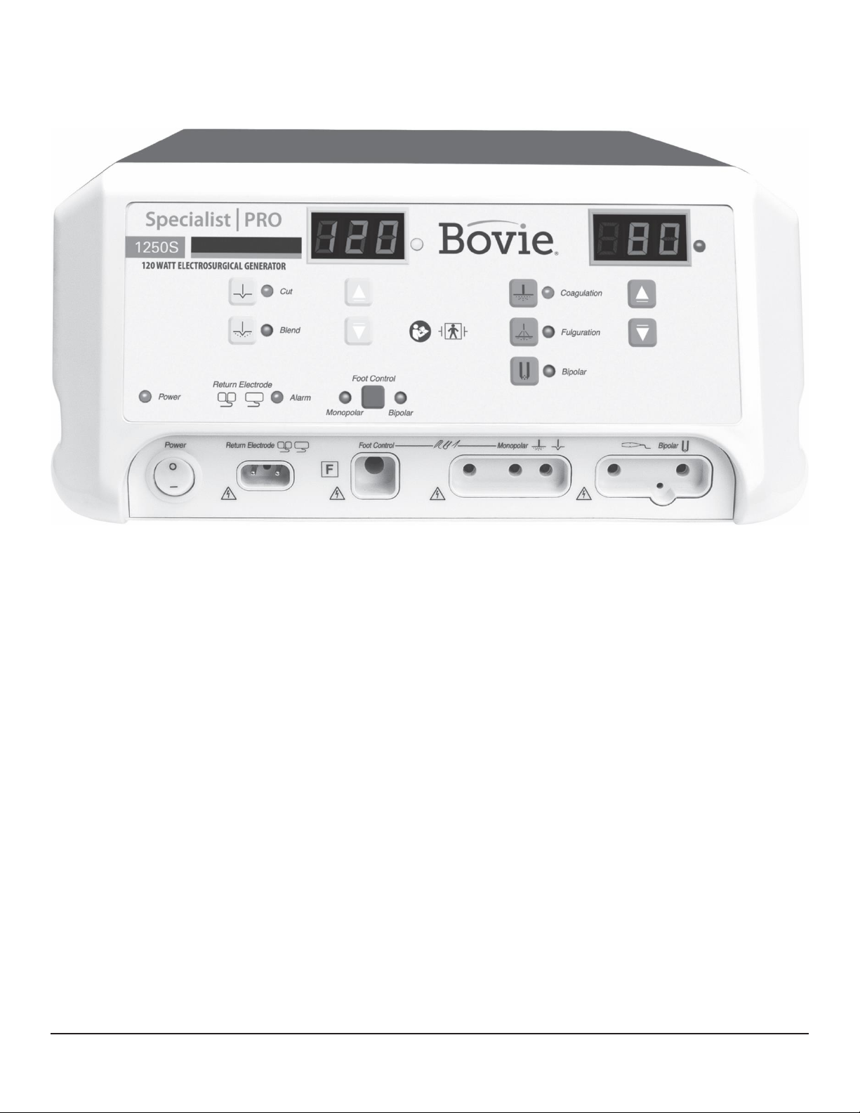
FRONT PANEL
Figure 2 –1 Layout of controls, indicators, and receptacles on the front panel

Bovie Medical Corporation
18
SYMBOLS ON THE FRONT PANEL
SYMBOLS
DESCRIPTION
Cut Controls
Cut mode
Blend mode
Coag Controls
Coagulation Mode
Fulguration Mode
Bipolar Controls
Bipolar Mode
Indicators
Split Return Electrode
Solid Return Electrode
Regulatory Symbology
Mandatory: Refer to instruction manual/guide.
Defibrillator Proof Type BF Equipment
RF Isolated –patient connections are isolated from earth at high frequency.
Warning: Dangerous voltage.
Power Switch and Handpiece
Connectors
Patient Return Electrode
Monopolar Output
Bipolar Output
Other manuals for SPECIALIST PRO
1
Table of contents
Other Bovie Portable Generator manuals

Popular Portable Generator manuals by other brands


DUROMAX
DUROMAX DUAL FUEL HYBRID ELITE XP5000EHC user manual

Briggs & Stratton
Briggs & Stratton Kincrome KP10105 Operator's manual

Solution Ozone
Solution Ozone SSO-O3-SPA01 user manual

Power Products
Power Products CERVASCAN Instructions for use

Ayce
Ayce PDS 3000 Operator's manual

Champion Global Power Equipment
Champion Global Power Equipment 200989 quick start


