Bowa 050-230 User manual

MN030-423-IFU-M098-050230-S2-20100401 03/10
Gebrauchsanweisung
Prüfgerät für
Elektrodenhandgriffe und Kabel
050-230

Seite 2 Prüfgerät MN030-423-I U-M098-050230-S2-20100401
Inhal
1. Anschluss-Positionen 3
2. Bestimmungsgemäße Verwendung 4
3. Bedienung 4
3.1 Einschalten und unktionstest 4
3.2 Prüfen von Neutralelektroden-Anschlussleitungen 5
3.3 Prüfen von Bipolaren-Anschlussleitungen 5
3.4 Prüfen von Ligator-Anschlussleitungen 5
3.5 Prüfen von einpoligen Anschlussleitungen 6
3.6 Prüfen von Handgriffen mit ingerschaltern 6
3.7 Prüfen von Pedal- ußschaltern 6
4. Desinfizieren und Reinigen 7
5. Wartung/Reparatur 7
5.1 Technischer Service 7
6. Entsorgung 8
7. Technische Daten und Ausführung 8
8. Notizen 9

050-230-I U-V1.0-MN030-423-S2-20100401 Prüfgerät Seite 3
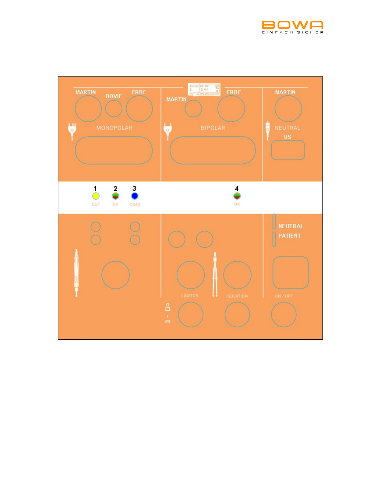
1. Anschluss-Posi ionen

Seite 4 Prüfgerät MN030-423-I U-M098-050230-S2-20100401
2. Bes immungsgemäße Verwendung
Das Prüfgerät dient zur Überprüfung von monopolaren Handgriffen sowie mono- und
bipolaren Handgriffen und Kabeln mit Valleylab-, ERBE- oder Martin-kompatiblem
Anschluss.
3. Bedienung
3.1 Einschalten und Funktionstest
• Steckernetzteil an Kleinspannungsbuchse mit Bajonettverschluss mit kurzer
Drehung anschließen.
• Steckernetzteil in Steckdose bauseitig stecken 100-240V AC möglich.
• Ein- / Ausschalter betätigen
Es folgt ein sichtbarer Einschalttest:
Alle LEDs leuchten
Ligator- & Isolation-Schalter blinken wechselseitig
danach leuchten die Statusanzeigen-LEDs von links nach rechts
1 2 3 4
Gelb – grün – blau – rot
Gelb – rot – blau – grün
Dummywiderstand wird in den Schaltkreis geschaltet um Sensor und OPV zu
testen.
- orange - orange
• Wenn Statusanzeige 2 und 4 orange leuchten wurde der Einschalt- und
Simulationstest erfolgreich abgeschossen.
Kabelprüfer ist nun betriebsbereit.
- oder -
Wenn Statusanzeige 4 orange / rot blinkt liegt ein ehler vor.
Bitte wenden Sie sich an den technischen Service (siehe Kapitel
„5.1 Technischer Service“).
Ach ung:
Aus mess echnischen Gründen darf immer nur ein Prüfling ges eck sein!

050-230-I U-V1.0-MN030-423-S2-20100401 Prüfgerät Seite 5
3.2 Prüfen von Neutralelektroden-Anschlussleitungen
Prüfen der unterschiedlichen Neutralelektrodenleitungen (rechte Seite des Gerätes).
Wählen Sie zu Ihrem Kabel die passende Steckung und adaptieren Sie zuerst die
Geräteseite danach die Instrumentenseite.
Statusanzeige „4“ wird bei gutem Prüfling grün leuchten. Jetzt sollte der Prüfling hin
und her bewegt werden um zu erkennen, ob ein Wackelkontakt vorhanden ist.
Gleichzeitig beginnt der Isolationsschalter zu blinken. Das bedeutet der
entsprechende Schalter muss betätigt werden um die Isolationsprüfung
durchzuführen.
Ist die Leitung in Ordnung, wird die Statusanzeige „4“ grün leuchten, auch hier muss
der Prüfling hin und her bewegt werden. Danach Prüfling entfernen.
Ist der Prüfling nich in Ordnung leuchtet die Statusanzeige „4“ rot. In diesem all
den Prüfling entfernen und entsprechend markieren.
3.3 Prüfen von Bipolaren-Anschlussleitungen
Wählen Sie zu Ihrem Kabel die passende Steckung. Danach verfahren Sie wie bei
den Neutralelektrodenleitungen.
3.4 Prüfen von Ligator-Anschlussleitungen
Schalten Sie den Schalter, welcher mit Ligator bezeichnet, ist „EIN“.
Wählen Sie zu Ihrem Kabel die passende Steckung und adaptieren Sie zuerst die
Geräteseite danach die Instrumentenseite.
Statusanzeige „4“ wird bei gutem Prüfling grün leuchten. Jetzt sollte der Prüfling hin
und her bewegt werden, um zu erkennen ob ein Wackelkontakt vorhanden ist.
Gleichzeitig beginnt der Isolationsschalter zu blinken. Das bedeutet der
entsprechende Schalter muss betätigt werden um die Isolationsprüfung durch zu
führen.
Ist die Leitung in Ordnung wird die Statusanzeige „4“ grün leuchten, auch hier muss
der Prüfling hin und her bewegt werden. Danach Prüfling entfernen.
Ist der Prüfling nich in Ordnung leuchtet die Statusanzeige „4“ rot oder bleibt
orange. In diesem all den Prüfling entfernen und entsprechend markieren.
Seite 6 Prüfgerät MN030-423-I U-M098-050230-S2-20100401
3.5 Prüfen von einpoligen Anschlussleitungen
Wählen Sie zu Ihrem Kabel die passende Steckung auf der linken Seite des
Prüfgerätes und adaptieren Sie zuerst die Geräteseite danach die Instrumentenseite.
Statusanzeige „2“ wird bei gutem Prüfling grün leuchten jetzt sollte der Prüfling hin
und her bewegt werden, um einen evtl. vorhandenen Wackelkontakt festzustellen.
Ist die Leitung nich in Ordnung wird die Statusanzeige „2“ rot blinken. In diesem
all den Prüfling entfernen und entsprechend markieren.
3.6 Prüfen von Handgriffen mit Fingerschaltern
Wählen Sie zu Ihrem Kabel die passende Steckung auf der linken Seite des
Prüfgerätes und adaptieren Sie zuerst die Geräteseite. Danach stecken Sie den
Handgriff in den vorgesehenen waagrechten Kontaktstift. Daraufhin muss die
Statusanzeige „2“ grün leuchten. Bewegen Sie das Kabel hin und her, die
Statusanzeige „2“ muss dauernd grün leuchten.
Ist das Kabel nich in Ordnung wird die Statusanzeige „2“ rot blinken. In diesem all
den Prüfling entfernen und entsprechend markieren.
Betätigen Sie die Taste gelb für Cut. Es muss die Statusanzeige „1“ gelb leuchten.
Ist die Taste nich in Ordnung wird die Statusanzeige „2“ rot blinken oder zeigt keine
Reaktion. In diesem all den Prüfling entfernen und entsprechend markieren.
Betätigen Sie die Taste blau für COAG. Es muss die Statusanzeige „3“ blau
leuchten.
Ist die Taste nich in Ordnung wird die Statusanzeige „2“ rot blinken oder zeigt keine
Reaktion. In diesem all den Prüfling entfernen und entsprechend markieren.
3.7 Prüfen von Pedal-Fußschaltern
Wählen Sie die Buchse an der rontseite des Prüfgerätes. Adaptieren Sie den uß-
schalter.
Bedienen Sie nacheinander die Pedale. Die Statusanzeige wird entsprechend der
Pedalfarbe leuchten. Statusanzeige „2“ ist für das dritte Pedal und wird von orange
auf grün wechseln.
Ist der Pedalfußschalter nicht in Ordnung werden die Anzeigen nicht reagieren und
nicht leuchten, die Statusanzeige „2“ bleibt orange. In diesem all den Prüfling
entfernen und entsprechend markieren.
050-230-I U-V1.0-MN030-423-S2-20100401 Prüfgerät Seite 7
4. Desinfizieren und Reinigen
Hinweis
Beschädigung des Prüfgerä es durch falsche Handhabung!
Sterilisieren Sie das Prüfgerät niemals. Reinigen oder desinfizieren Sie es.
Warnung
S romschlag- und Brandgefahr!
Ziehen Sie vor der Reinigung den Netzstecker.
Verwenden Sie für die lächenreinigung zugelassene Reinigungs-
/Desinfektionsmittel nur nach Anweisung des Herstellers.
Stellen Sie sicher, dass keine lüssigkeit in das Gerät eindringt.
Reinigung
Das Gehäuse mit einem feuchten Lappen und mildem Reinigungsmittel abwischen.
Zur Reinigung keine Scheuer- oder Lösungsmi el verwenden. Schmutz
und/oder euchtigkeit in den Anschlüssen kann die Prüfungen beeinträchtigen.
5. War ung/Repara ur
Hinweis
Beschädigung des Prüfgerä es durch eigenhändig ausgeführ e Repara urmaß-
nahmen und Modifika ionen!
Wenden Sie sich im Reparaturfall ausschließlich an die unten genannte Service-
Adresse.
ühren Sie keinesfalls eigenhändig Reparaturen durch.
BOWA übernimmt die Haftung für Sicherheit, Zuverlässigkeit und Leistung des
Prüfgerätes unter folgenden Bedingungen:
• Alle Anweisungen zur Installation und zum bestimmungsgemäßen
Gebrauch gemäß dieser Gebrauchsanweisung wurden genau befolgt.
• Änderungen, Reparaturen, Neueinstellungen u. Ä. wurden nur von
Personen ausgeführt, die für diese Arbeiten von BOWA autorisiert wurden.
• Die elektrischen Installationen in dem betreffenden Raum entsprechen den
örtlichen Vorschriften und gesetzlichen Bestimmungen.
5.1 echnischer Service
ür Wartung und Reparatur wenden Sie sich an folgende Service-Adresse:
BOWA-electronic GmbH & Co. KG
Heinrich-Hertz-Strasse 4–10
72810 Gomaringen/Germany
Telefon +49 (0) 7072-6002-0
Telefax +49 (0) 7072-6002-33
oder im Internet unter:
www.bowa-medical.com

Seite 8 Prüfgerät MN030-423-I U-M098-050230-S2-20100401
6. En sorgung
Das Gerät kann am Ende seiner Nutungsdauer wie gewöhnlicher Elektronikschrott
entsorgt werden. Die Entsorgung des Prüfgerätes, des Verpackungsmaterials sowie
des Zubehörs muss unbedingt nach den jeweils geltenden länderspezifischen
Vorschriften und Gesetzen erfolgen.
7. Technische Da en und Ausführung
S eckerne z eil: 100 VAC – 240 AC, 50 / 60Hz
Eingangsstrom 400mA
Spannungsgeregelt, strombegrenzt
Ableitstrom < 10uA
Austauschbare Primäradapter
Nennspannung: 15 Volt DC
Nenns rom: 0,5 A DC
Frequenz MCU: 16 MHz
Frequenz Handgriff: 20 kHz
Frequenz Kabelmessung: 5 bis 20 Hz
Schni s elle in ern: RS232
Prüfkri erien: Widerstand Anschlussleitungen < 10 Ohm
Handgrifftasten < 220 Ohm
Handgriffaktivleitung < 20 Ohm
Isolationswiderstand Leiter z. Leiter > 1 MOhm
Von Instrumentenseite aus gemessen,
Ligator- Anschlusskabel entsprechend Spezifikation
S a us-Anzeigen: orange (beide Statusanzeigen) = Betriebsbereit
grün (dauernd) = Prüfling IN ORDNUNG
gelb = CUT – Taste betätigt
blau = COAG – Taste betätigt
rot / keine Reaktion = EHLER
Gehäuse: Kunststoff mit Aufstellfüßen zum Pult.
Abmessungen: B 240 x T 198 x H 110 mm
Gewicht: 1,5 kg
Isola ion / Klassifizierung:
Normenkonformität DIN EN 61010:2002 + A1:2002 + A2:2004
EMV DIN EN 61326-1:2006
Schutzklasse II
Temperatur Rel. Feuchtigkeit Luftdruck
Lagerbedingungen: -20 °C bis +70 °C 10 - 100% 500 - 1060 hPa
Umgebungs-
bedingungen: -10 °C bis +60 °C 10 - 100% 800 - 1060 hPa

050-230-I U-V1.0-MN030-423-S2-20100401 Prüfgerät Seite 9
8. No izen

CE-Kennzeichnung gemäß
Richtlinie 2006/95/EG
BOWA-electronic GmbH & Co. KG
Heinrich-Hertz-Straße 4-10
D-72810 Gomaringen │ Germany
Telefon +49 (0) 7072 / 6002 - 0
Telefax +49 (0) 7072 / 6002 - 33
[email protected] │ bowa-medical.com
Technische Änderungen vorbehalten! MADE IN GERMANY
050-230-I U-V1.0-MN030-423-S2-20100401

MN030-423-IFU-M098-050230-S2-20100401 03/10
Opera ing Manual
Testing Device for
Electrode Handles and Cables
050-230

Page 2 Testing Device MN030-423-I U-M098-050230-S2-20100401
Con en s
1. Connection Positions 3
2. Intended Use 4
3. Operation 4
3.1 Switching on and functional test 4
3.2 Testing neutral electrode connecting cables 5
3.3 Testing bipolar connecting cables 5
3.4 Testing Ligator connecting cables 5
3.5 Testing unipolar connecting cables 6
3.6 Testing handles with finger switches 6
3.7 Testing pedal foot switches 6
4. Disinfecting and Cleaning 7
5. Maintenance/Repairs 7
5.1 Technical Service Center 7
6. Disposal 8
7. Technical Data and Version 8
8. Notes 9
MN030-423-I U-M098-050230-S2-20100401 Testing Device Page 3
1. Connec ion Posi ions

Page 4 Testing Device MN030-423-I U-M098-050230-S2-20100401
2. In ended Use
The testing device is designed for testing monopolar handles as well as monopolar
and bipolar handles and cables with a Valleylab, ERBE or Martin-compatible
connection.
3. Opera ion
3.1 Switching on and functional test
• Connect the adapter to the low-voltage socket with a ‘push and turn’ bayonet
fitting.
• Plug the adapter into a locally provided socket; 100-240V AC possible.
• Press the On / Off switch
A visible switch-on test is executed:
All the LEDs illuminate
The Ligator and the Insulation switch flash alternately,
the status indicator LEDs subsequently illuminate from left to right
1 2 3 4
Yellow – Green – Blue – Red
Yellow – Red – Blue – Green
The dummy resistance is activated in the circuit in order to test the sensor and
operational amplifier.
- Orange - Orange
• The switch-on test and the simulation test have been successfully completed
when the status indicators 2 and 4 illuminate orange.
The cable testing device is now ready for operation.
- or -
An error is indicated by the status indicator 4 flashing orange / red.
Please contact the Technical Service Center (see section “5.1 Technical
Service Center”).
Cau ion:
Due o echnical-measuremen reasons, only one es i em can be inser ed a a
ime!

MN030-423-I U-M098-050230-S2-20100401 Testing Device Page 5
3.2 esting neutral electrode connecting cables
Test the various neutral electrode cables (right-hand side of the cable testing device).
Select the appropriate plug-in mount for your cable; then connect the device side and
subsequently the instrument side.
Status indicator “4” illuminates green if the test item is ok. The test item should now
be moved back and forth to test whether there is a defective contact or not. The
Insulation switch starts to flash at the same time. This means that the respective
switch must be pressed to initiate the insulation test.
If the cable is ok, the status indicator “4” illuminates green; the test item should also
be moved back and forth. Subsequently remove the test item.
If the test item is no ok, the status indicator “4” illuminates red. In this case, remove
the test item and mark it accordingly.
3.3 esting bipolar connecting cables
Select the appropriate plug-in mount for your cable. Then proceed as described for
the neutral electrode cables.
3.4 esting Ligator connecting cables
Set the Ligator switch to “ON”.
Select the appropriate plug-in mount for your cable; then connect the device side and
subsequently the instrument side.
The status indicator “4” illuminates green if the test item is ok. The test item should
now be moved back and forth to test whether there is a defective contact or not. The
insulation switch starts to flash at the same time. This means that the respective
switch must be pressed to initiate the insulation test.
If the cable is ok, the status indicator “4” illuminates green; the test item should also
be moved back and forth. Subsequently remove the test item.
If the test item is no ok, the status indicator “4” illuminates red or remains orange. In
this case, remove the test item and mark it accordingly.

Page 6 Testing Device MN030-423-I U-M098-050230-S2-20100401
3.5 esting unipolar connecting cables
Select the appropriate plug-in mount on the left-hand side of the testing device for
your cable; then connect the device side and subsequently the instrument side.
The status indicator “2” illuminates green if the test item is ok. The test item should
now be moved back and forth to test whether there is a defective contact or not.
If the cable is no ok, the status indicator “2” flashes red. In this case, remove the
test item and mark it accordingly.
3.6 esting handles with finger switches
Select the appropriate plug-in mount on the left-hand side of the testing device for
your cable; then connect the device side. Then insert the handle into the provided
horizontal contact pin. The status indicator “2” must illuminate green. Move the cable
back and forth, the status indicator “2” must continuously illuminate green.
If the cable is no ok, the status indicator “2” flashes red. In this case, remove the
test item and mark it accordingly.
Press the yellow key for Cut. The status indicator “1” must illuminate yellow.
If the key is no ok, the status indicator “2” flashes red or there is no reaction at all.
In this case, remove the test item and mark it accordingly.
Press the blue key for COAG. The status indicator “3” must illuminate blue.
If the key is no ok, the status indicator “2” flashes red or there is no reaction at all.
In this case, remove the test item and mark it accordingly.
3.7 esting pedal foot switches
Select the socket located on the front of the testing device. Connect the foot switch.
Operate the pedals one after the other. The status indicator illuminates according to
the pedal color. The status indicator “2” is for the third pedal and changes from
orange to green.
If the pedal switch is no ok, the indicators do not react or illuminate; the status
indicator “2” remains orange. In this case, remove the test item and mark it
accordingly.

MN030-423-I U-M098-050230-S2-20100401 Testing Device Page 7
4. Disinfec ing and Cleaning
No e
Incorrec handling of he es ing device may resul in damage!
Never sterilize the testing device. Always clean or disinfect it instead.
Warning
Risk of elec ric shock and fire!
Always disconnect the power plug prior to cleaning.
When cleaning surfaces, only use cleaning agents/disinfectants approved by the
manufacturer.
Make sure that liquid does not enter the device.
Cleaning
Use a damp cloth and mild cleaning agent to clean the casing. Never use abrasive
cleaning agen s or solven s. Dirt and/or moisture in the connections can have a
negative effect on testing.
5. Main enance/Repairs
No e
To preven damages, do no a emp repairs or modifica ions o he es ing
device yourself!
If repairs are necessary, contact the Technical Service Center specified below.
Never attempt repairs to the device yourself.
BOWA will be liable for the safety, reliability and performance of the testing device
under the following conditions:
• All the instructions regarding installation as well as correct and intended
usage contained in this operating manual have been followed precisely.
• Modifications, repairs, new settings, etc. have been carried out by BOWA
authorized service technicians.
• Electrical installations in the relevant room meet local requirements and
statutory provisions.
5.1 echnical Service Center
Contact the following Technical Service Center for maintenance and repair work:
BOWA-electronic GmbH & Co. KG
Heinrich-Hertz-Strasse 4–10
72810 Gomaringen, Germany
Phone +49 (0) 7072-6002-0
ax +49 (0) 7072-6002-33
or visit our website:
www.bowa-medical.com

Page 8 Testing Device MN030-423-I U-M098-050230-S2-20100401
6. Disposal
At the end of its service life, the device can be disposed of as normal electrical and
electronic equipment waste. The disposal of the testing device, packaging material
and accessories must be in accordance with relevant country-specific regulations
and laws.
7. Technical Da a and Version
Adap er: 100 VAC – 240 AC, 50 / 60Hz
Input current 400mA
Voltage regulated, current limited
Leakage current < 10uA
Replaceable primary adapter
Ra ed vol age: 15 V DC
Ra ed curren : 0.5 A DC
Frequency MCU: 16 MHz
Frequency handle: 20 kHz
Frequency cable measuremen : 5 to 20 Hz
In ernal in erface: RS232
Tes cri eria: Connecting cable resistance < 10 Ohms
Handle keys < 220 Ohms
Active cable handle < 20 Ohms
Insulation resistance conductor to conductor > 1 mOhms
Measured from the instrument side,
Ligator connection cable according to specifications
S a us indica ors: Orange (both status indicators) = ready for operation
Green (continuously) = test IS OK
Yellow = CUT – key pressed
Blue = COAG – key pressed
Red / No reaction = ERROR
Casing: Plastic with feet for console position.
Dimensions: W 240 x D 198 x H 110 mm
Weight: 1.5 kg
Insula ion / Classifica ion:
Compliance with standards DIN EN 61010:2002 + A1:2002 + A2:2004
EMC DIN EN 61326-1:2006
Protection rating II
Temperature Rel. humidity Atmospheric
pressure
S orage condi ions: -20 °C to +70 °C 10 - 100% 500 - 1060 hPa
Ambien condi ions: -10 °C to +60 °C 10 - 100% 800 - 1060 hPa

MN030-423-I U-M098-050230-S2-20100401 Testing Device Page 9
8. No es

CE Mark in accordance with
Directive 2006/95/EC
BOWA-electronic GmbH & Co. KG
Heinrich-Hertz-Straße 4-10
D-72810 Gomaringen │ Germany
Phone +49 (0) 7072 / 6002 - 0
ax +49 (0) 7072 / 6002 - 33
[email protected] │ bowa-medical.com
Technical details subject to change! MADE IN GERMANY
050-230-I U-V1.0-MN030-423-S2-20100401
Table of contents
Languages:


