Bowers M1 User manual
+44 (0) 1276 469 866
Bowers Group Fax +44 (0) 1276 401 498
Unit 3, Albany Court, Web : www.bowersgroup.co.uk
Albany Park, Camberley, Email : sales@bowersgroup.co.uk
Surrey, GU16 7QR
M
M1
1
/
/
M
M3
3
D
Di
is
sp
pl
la
ay
y
u
un
ni
it
ts
s
f
fo
or
r
1
1
o
or
r
2
2
a
ai
ir
r
g
ga
au
ug
ge
es
s
USER’S MANUAL
Firmware 2.1

M1 –M3 Display Units
Page 2
TABLE OF CONTENTS
TABLE OF CONTENTS __________________________________________ 2
1. FOREWORDS _________________________________________________ 4
2. INTRODUCTION _______________________________________________ 6
2.1. PRODUCT PRESENTATION ........................................................................6
2.2. VERSIONS ....................................................................................................6
2.3. CHARACTERISTICS.....................................................................................7
2.3.1. MAIN TECHNICAL CHARACTERISTICS...............................................7
2.3.2. DIMENSION AND INSTALLATION ........................................................7
2.3.3. CONTENTS OF THE PACKAGING .....................................................10
2.3.4. ACCESSORIES....................................................................................11
2.3.5. OPTIONS / CABLES ............................................................................12
2.3.6. CONNECTORS....................................................................................15
2.3.7. STANDARD CABLING –RESTRICTOR CHOICE...............................15
2.3.8. CABLING WITH BY-PASS NOZZLE (INTEGRATED RESTRICTOR).18
2.3.9. THE RS232 COMMUNICATION PORT................................................19
2.3.10. MINI-USB CONNECTOR....................................................................20
2.3.11. THE 24VDC CONNECTOR................................................................20
2.3.12. THE USB STICK CONNECTOR ........................................................20
2.3.12. THE FOOTSWITCH CONNECTOR...................................................20
3. AIR PREPARATION UNIT –AIR PIPES ____________________________ 22
3.1. AIR PREPARATION UNIT...........................................................................22
3.2. AIR PIPES ...................................................................................................22
4. QUICK START ________________________________________________ 24
5. GRAPHICAL INTERFACE _______________________________________ 25
5.1. 2 MAIN PARTS............................................................................................25
5.2. GENERAL....................................................................................................26
5.3. CONFIGURATION WINDOWS ...................................................................28
5.4. VIRTUAL KEYBOARD.................................................................................29
6. CONFIGURATION OF THE DEVICE FOR MEASUREMENT ____________ 30
6.1. DEFINITION.................................................................................................31
6.1.1. PART 1.................................................................................................32
6.1.2. PART 2.................................................................................................35
6.1.3. PART 3 - CLASS..................................................................................36
6.1.4. PART 3 CONTROL LIMIT ....................................................................38
6.2. DISPLAY......................................................................................................39
6.3. SETUP.........................................................................................................41
6.3.1. CALIBRATION OF THE AIR GAUGE...................................................42
6.3.1.1. CALIBRATION IN 2 POINTS.............................................................42
6.3.1.2. CALIBRATION IN 3 POINTS.............................................................45
6.3.2. M-BUS MODULES ...............................................................................46
6.4. CONFIGURATION.......................................................................................52
6.5. LOCK...........................................................................................................55
6.6. MEASURE...................................................................................................57
7. MEASURING SCREEN _________________________________________ 58
7.1. LATERAL BUTTON FUNCTIONS ...............................................................58
7.2. CHOICE OF THE NEEDLE INDICATOR STYLE ........................................61

M1 –M3 Display units
Page 3
7.3. TEMPORARY DYNAMIC MODE.................................................................62
7.4. DISPLAY MODE WITHOUT TOLERANCE .................................................63
8. USB COMMUNICATION_________________________________________ 64
9. RS232 COMMUNICATION_______________________________________ 66
9.1. COMMANDS..............................................................................................66
9.1.1. GENERAL...........................................................................................66
9.1.2. COMMAND LIST ................................................................................67
9.1.2.1. WINDOW PART..............................................................................67
9.1.2.1. WINDOW DISPLAY.........................................................................68
9.1.2.2. WINDOW CONFIGURATION..........................................................68
9.1.2.3. WINDOW « LOCK »........................................................................69
9.1.2.4. MEASURING SCREEN...................................................................70
10. DATA EXPORT ON USB KEYS ___________________________________ 71
10.1. STANDARD MODE : .................................................................................71
10.2. ADVANCED MODE : .................................................................................72
11. CONFIGURATION OF THE UNIT WITH QR CODES __________________ 73
11.1. CALIBRATION COMMANDS:....................................................................73
11.2. ADVANCED CONFIGURATION................................................................74
11.3. EXAMPLE OF QR CODE CONFIGURATION ...........................................74
12. MODBUS RTU Protocol _________________________________________ 76
13. OPTIONAL I/O MODULE ________________________________________ 79
13.1. MB-IO MODULE ........................................................................................79
13.2. MB-RL MODULE .......................................................................................82
13.3. MB-TP MODULE –FOR TEMPERATURE COMPENSATION..................86
14. FACTORY RESET _____________________________________________ 90
15. FIRMWARE UPDATE___________________________________________ 91

M1 –M3 Display Units
Page 4
1. FOREWORDS
ONE YEAR LIMITED GUARANTEE FOR MULTIVISION
MANUFACTURER'S RESPONSIBILITY
SPARE PARTS AND LABOUR.
The manufacturer commits himself to pay for repair or replacement costs (labour
costs included) during a period of one year as from the date the guarantee came into
force. The spare parts can be new or renovated and are guaranteed until the end of
the initial guarantee period.
FIRST END-USER COVERAGE.
This guarantee applies only to the first end-user of the product and is not assignable
to any other subsequent purchaser or user.
RESTRICTIONS.
Any accessory or expansion item not included in the original factory packaging is not
guaranteed.
The present guarantee does not cover: installation or repair costs, damages resulting
from circumstances beyond the manufacturer's control like damages following acts of
God, misuse, or careless mistake from the user, damages during the transport or due
to a wrong installation, use or application, such as any material damage caused by
the use of non-supplied products, components or accessories. It also does not cover
products modified without any written approval from the manufacturer, including
electrical or mechanical modification, removal of serial numbers or of the
manufacturer's trademarks or of any other identification.
THE SOLE RECOURSE UNDER THIS GUARANTEE SHALL BE THE REPAIR OR
THE REPLACEMENT OF DEFECTIVE PARTS AS INDICATED ABOVE. UNDER
NO CIRCUMSTANCES THE MANUFACTURER CAN BE HELD LIABLE FOR
INDIRECT OR SPECIAL DAMAGES OR FOR DAMAGES RESULTING FROM THE
USE OF THE PRODUCT, INCLUDING ANY LOSS OF DATA, BUSINESS OR
PROFIT, AND WHETHER THESE DAMAGES CAN BE FORESEEN OR NOT AND
WHETER THEY ARE BASED ON A GUARANTEE VIOLATION OR NOT.
THE PRESENT GUARANTEE REPLACES ANY OTHER EXPRESSED OR IMPLIED
GUARANTEE INCLUDING BUT NOT LIMITED TO ANY GUARANTEE OF
MARKETING OR ADEQUACY FOR A PARTICULAR USE; AND ALL THESE
GUARANTEES ARE EXPRESSLY EXCLUDED AND CANCELLED.
WARNING
The information contained in this booklet can be changed without notice.

M1 –M3 Display units
Page 5
The manufacturer makes no warranty whatsoever with respect to the warranties of
commercial quality of this product or its suitability to a particular use.
The manufacturer is not responsible for mistakes that could be found in this
handbook and also for direct or indirect damage resulting from the equipment, its
performances and the use of this product.
It is the responsibility of the user to verify the calibration of the display before
measuring and it is advised to check periodically the calibration and
measurement performance.
CLEANING
Use a soft cotton cloth slightly soaked with an ethyl alcohol based product.
DO NOT USE the following products: acetone, benzene, toluene and halogens
hydrocarbons.

M1 –M3 Display Units
Page 6
2. INTRODUCTION
2.1. PRODUCT PRESENTATION
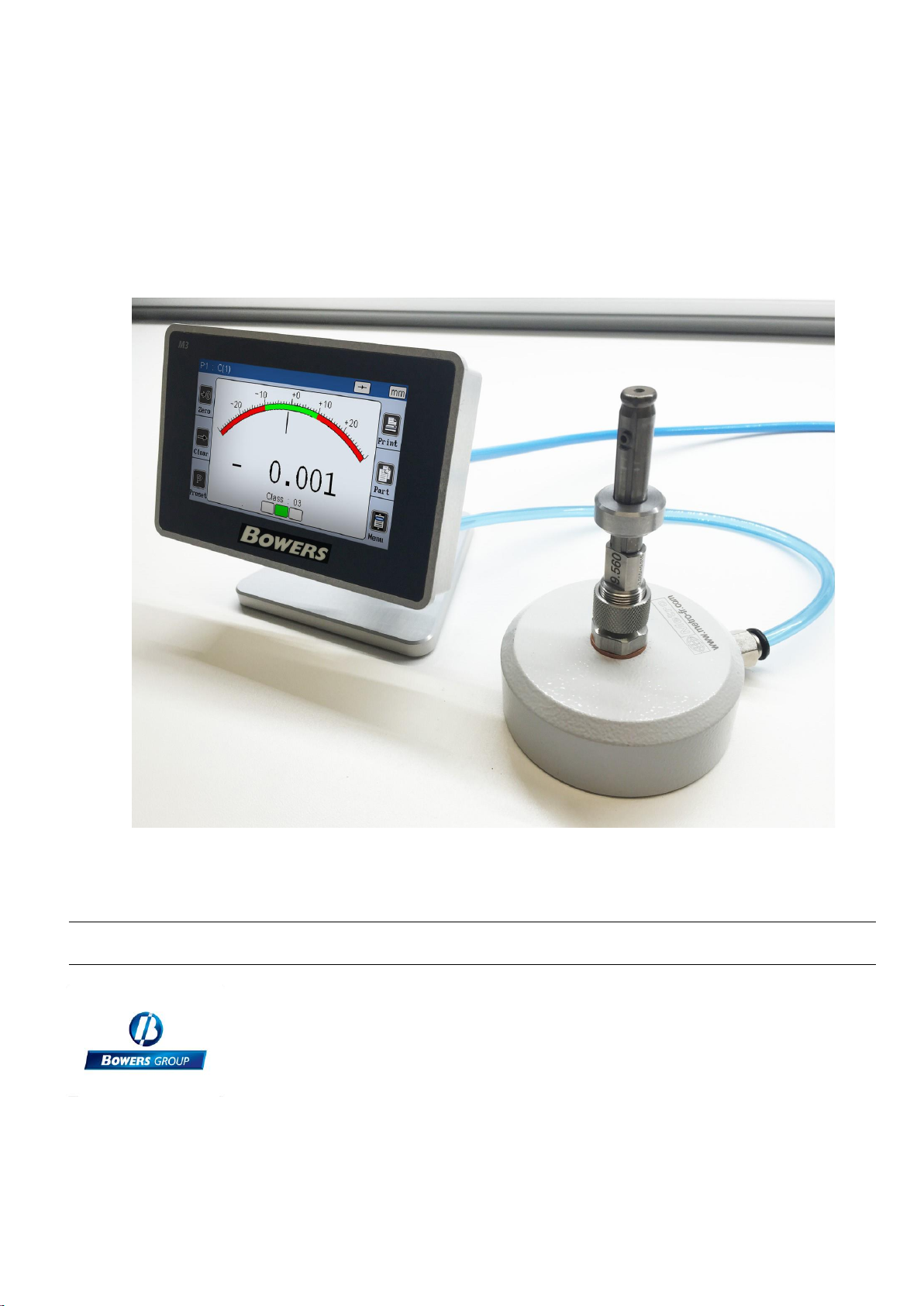
The M1 and M3 display units allow making dimensional control using 1 or 2 air
gauges. Depending on the version it is possible to make simple measurement (with
one air gauge), or display 2 characteristics on the screen and can make static
measurement or dynamic (Max, Min, Max-Min…)
The M1-M3 can be connected to a PC thanks to its RS232 or USB connection.
A footswitch can be connected in order to transfer measurements.
The M1 / M3 displays for air gauges requires a minimum of 2 masters for calibration.
2.2. VERSIONS
REF
Description
55-AIR 1 (M1)
Display unit M1 for 1 air gauge
55-AIR 2 (M3)
Display unit M3 for 2 air gauges or 1 air
gauge with 2 measuring levels

M1 –M3 Display units
Page 7
2.3. CHARACTERISTICS
2.3.1. Main technical characteristics
TFT colour touch screen display 4,3’’, resolution 480x272.
Static or dynamic measurements (Max, Min, Max-Min, Average, Median)
Analogue or digital display
1 or 2 measurement configurations (2 characteristics)
Possibility to select automatically the characteristic by using the air gauge or by
touching the screen.
Relative or absolute display
Display resolution (up to 0.1µm)
Metric (mm or µm) or Imperial (Inches) measurement
RS232 port for communication with a PC
USB port for communication and/or power supply
USB Stick for data saving on a CSV file
Optional connection of M-Bus modules
Measurement transfer by pressing a key, footswitch input or retro-command on
the RS232 port.
Operating temperature : +15°C to +30°C
Power supply from 85 to 265 VAC by using the supplied main transformer (or by
connecting it directly on your PC USB port, or through the 24 VDC screw
terminal.
Relative humidity : maximum 80%
Dimensions : width 130 mm, height 111 mm, depth 105 mm
Mass : 600 grams (700g with the power supply)
2.3.2. Dimension and installation

M1 –M3 Display Units
Page 8
The M3 is fitted with 4 thread M5 allowing to attach it. To access to these threads, it
is necessary to remove the 4 antiskid plastic parts.
It is also possible to panel mount the display, using bracket (see page 12)
Be careful not to use longer screw than M4*16.
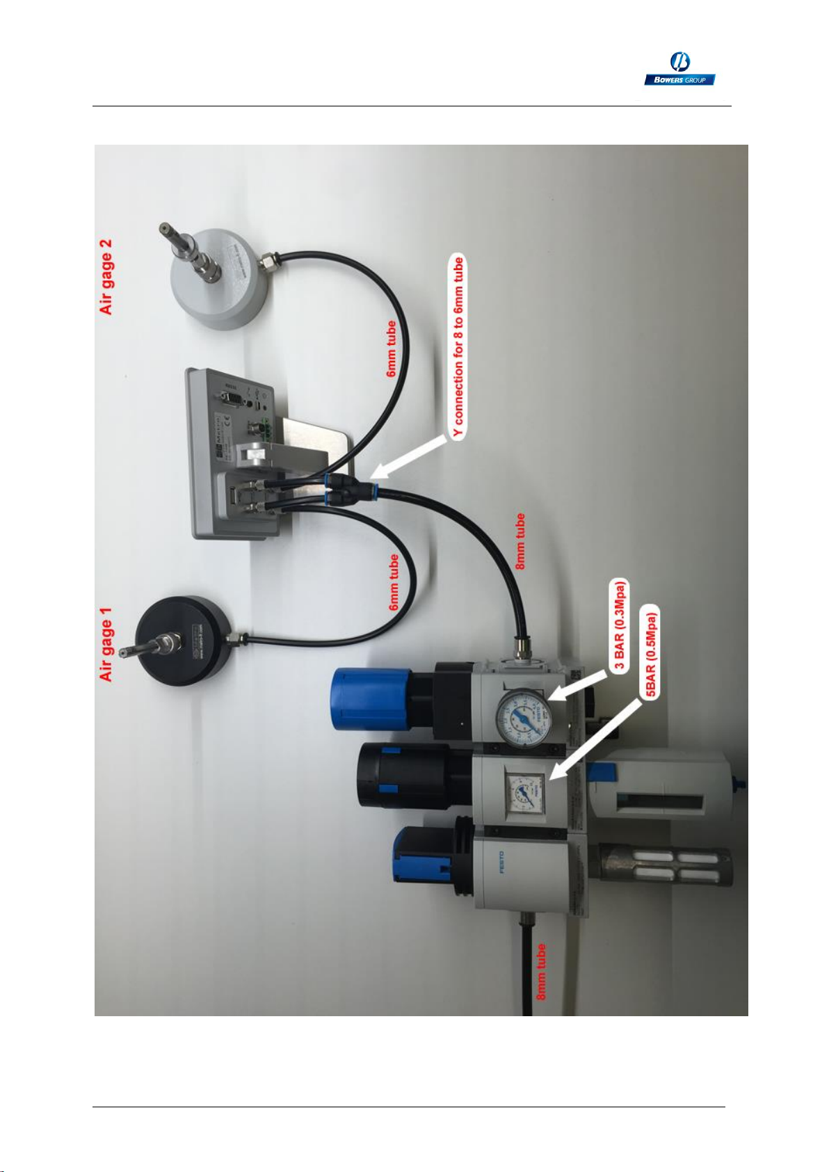
Pneumatic connections (see also chap.4) :
Remove the
antiskid parts
to attach it on
the table
M1 –M3 Display units
Page 9

M1 –M3 Display Units
Page 10
2.3.3. Contents of the packaging
The M1/3 package includes :
- 1 M1/3 display mounted on an orientable stand
- 1 USB cable, (length =1.8m) for power supply and/or data transfer
- 1 USB main adaptor for the display power supply. The M3 can also be powered by
a computer when connected to it with the USB.
- 1 Mini-CD containing the user manual.

M1 –M3 Display units
Page 11
2.3.4. Accessories
Reference
Description
Picture
55-MBV001
Air preparation unit :
It is mandatory to use a
precision regulation system,
otherwise the measurements
will not be stable.
We can supply the adapted
air preparation unit from SMC,
including stop valve, filter and
regulator + precision
regulator.
The precision regulator must
be adjusted at 3 BARS
(0.3MPa)
N/A
For M3 displays.
It allows to divide the 8mm
tube at the output of the air
preparation unit into 2 tubes
of 6 mm adapted for the
connection on the M3 input.
N/A
Soft polyurethane tubes
6*4mm :
The M1 / M3 are fitted with 2
connectors for air tube with
6mm external diameter and
4mm internal diameter.
We advise to use soft
polyurethane tubes from
SMC, because their flexibility
prevent the display to knock
over due to the pressure of
the tubes on the table.
N/A
Soft polyurethane tubes
8*5mm :
The air preparation unit is
fitted with a connection for
8mm tubes (external
diameter)

M1 –M3 Display Units
Page 12
2.3.5. Options / cables
Reference
Description
Picture
30-904-
4102
Footswitch :
This footswitch with a robust construction can be
configured in different ways: preset, measurement
transmission, start dynamic measurement etc...
N/A
Accessory for panel mounting.
To be installed instead of the stand.
30-804-
2130
This M-Bus module is fitted with 8 input/outputs
isolated with optocouplers allowing to get additional
functionalities, for example: output for Go/noGo, input
for preset or start dynamic measurement... The M-Bus
modules are mounted on an aluminum profile allowing
to mount them on a standard DIN rail.
Up to 4 modules can be mounted
N/A
The optional MB-RL module is
Fitted with 2 independent relays min and max, free of
potential that indicate the position of the measure
according to the part tolerances. The module is also
fitted with 6 inputs allowing
remote control display.
This MB-RL module is wired exactly like the #24136
optional board for Monocote displays. It allows then to
replace a Monocote by a M3 without changing the
machine wiring.

M1 –M3 Display units
Page 13
N/A
M-Bus cable for M3 :
This cable allows to connect the compatible M-Bus
modules on a M3 display unit. Length 1.5m
30-926-
5608
RS232 cable
This cable allows to connect a M1//M3 display to a
computer or a PLC.
30-926-
5521
This cable allows to connect a M1 /M3 display to a
Multiplexer Mux

M1 –M3 Display Units
Page 14
20-USB
RS232/USB cable converter :
This cable allows a M1/M3 display to
communicate with a computer. It creates a
virtual COM port on the computer. It is
delivered with a driver on a CD.
55-DP1
Ticket printer
Allows to print the displayed value of the
M1/M3
55-
HD3430-
BKK1B
QR code reader
2 main functions :
- Allow to send a configuration on the display
(part definition, tolerance, display type,
calibration of the air gauge, etc…)
- Send a Manufacturing order number. The
export file will take the name of the number
entered.
M1 –M3 Display units
Page 15
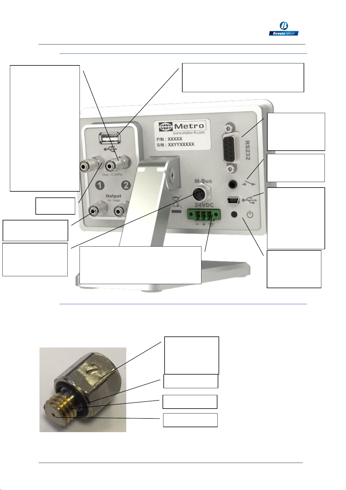
2.3.6. Connectors
2.3.7. Standard cabling –restrictor choice
The M1 or M3 are delivered with 1 or 2 restrictors of 0.5mm on the air input + 1 or 2
0.7mm restrictors as spare parts. The value of the restrictor is indicated as below:
7 =0.7mm
5=0.5mm
On/Off switch
(press 2s. for
shutting down)
2 inputs for AIR at
3BAR (0.2Mpa) (air
filtered at 5µm and
regulated at
0.1BAR /
0.01MPA). NEVER
EXCEED
4BAR/0.4MPA. It is
very recommended
to use Air
preparation set
from Bowers ref
55-MBV001. See
details on the chap.
3.3.4
RS232
connector for
connection to a
PC
Multi-function
foot switch
connector
Mini-USB
connector for
power supply
and
measurement
transfer to a
PC
To connect m-bus
modules
(optional)
24 VDC power supply. If you
choose this connector to power the
display, the ON-OFF switch will be
deactivated.
Output to the Air
gauge
USB Stick connector for data saving
on a CSV file.
Value of the
restrictor
7=0.7mm
O ring
M5 thread
Restrictor
Restrictor
M1 –M3 Display Units
Page 16
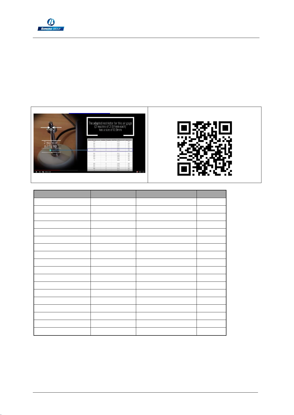
The following table shows some frequent cases to define which restrictor will be the
most applicable to your application.
If you order a turnkey solution at Bowers, we will deliver the display with the
applicable restrictor. But if you want to use the M1 / M3 display together with your
existing air gauge. Alternative restrictor may be required.
It is advised to contact Bowers for advices or confirmation around this subject.
Check this video for understanding the influence of the restrictor on the
linearity :
link to the video
Or scan the QR code :
Nozzle diameter in mm
number of nozzles
total flow surface in mm²
Restrictor
0,3
2
0,14
0,3
0,4
2
0,25
0,4
0,5
2
0,39
0,4
0,6
2
0,57
0,5
1
2
1,57
0,7
2,07
2
6,73
0,9
0,3
3
0,21
0,3
0,4
3
0,38
0,4
0,5
3
0,59
0,5
0,6
3
0,85
0,5
1
3
2,36
0,7
0,3
4
0,28
0,4
0,4
4
0,50
0,4
0,5
4
0,79
0,5
0,6
4
1,13
0,5
1
4
3,14
0,7

M1 –M3 Display units
Page 17
Example :
2.3.8.
PLEASE CONTACT BOWERS FOR FURTHER ADVICE
M1 –M3 Display Units
Page 18
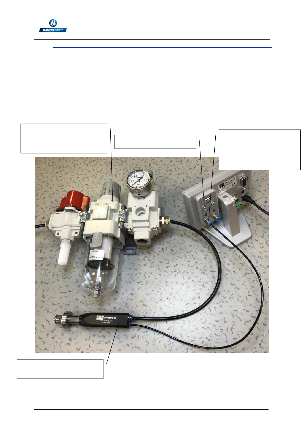
Cabling with by-pass nozzle (integrated restrictor)
Some air gauges are delivered with a by-pass nozzle (or integrated restrictor). It
means that the restrictor is integrated inside the air gauge itself, and there is no need
to install it on the display. NO RESTRICTOR ON THE DISPLAY.
This configuration allows to have a faster the reaction time and makes the installation
easier by removing the need to choose the adapted restrictor.
If you order a turn key solution at Bowers, it will generally be delivered according to
this principle.
Air gauge with by-pass
nozzle (integrated restrictor)
Regulation unit
ref 55-MBV001 (delivers
3BAR/0.3MPa pressure)
Stopper ref CMP-PNE-018
Standard push-in
connector, M5 thread.
Generally, for tube
external diam 3mm (ref
CMP-PNE-014)
Please discuss with Bowers for applications

M1 –M3 Display units
Page 19
2.3.9. THE RS232 COMMUNICATION PORT
The M3 is fitted with a RS232 port. It allows linking the M1/M3 to PC or an external
system. The port configuration is as following
9600 bauds, 8 bits, 1 stop bit, no parity
CONNECTOR PINOUT
It is fitted with a SUBD 9 pins female connector.
Pin
Signal
Direction
Description
1
Not used
2
RX
Input
Reception of data
3
TX
Output
Transfer of data
4
IN1
Input
Do not use. Only for firmware update
5
Gnd
-
Ground
6
Not used
7
IN2
Input
Do not use. Only for firmware update
8 &9
Not used

M1 –M3 Display Units
Page 20
2.3.10. MINI-USB connector
The mini-USB connector has 2 functions
1. Power supply through a wall mounted transformer. This transformer supplies a
regulated 5V/1A DC voltage.
2. Measurement transmission. If you connect your M3 to a PC, the PC will detect
and install automatically the M3 as a standard USB keyboard with the standard
drivers of your operating system (Windows, Mac OS etc..). When you send the
measurement, the value will be written on your PC screen where your cursor
is, in the same way as it would have been typed with a keyboard.
Message that appears when the M1/M3 has been correctly installed:
2.3.11. The 24VDC connector
It is advised to use this power supply when the M3 is panel mounted.
Using this power supply instead of the mini-USB will deactivate the ON-OFF switch.
Therefore, when the M3 is powered, it will start automatically.
2.3.12. The USB stick connector
It is possible to save measurements on a CSV file.
In this case the display must be set the following way:
ConfigurationTransferUSB key
Then once the user either press on the « PRINT » button of the measuring screen or
on the footswitch, one line will be added on the CSV file. (a « output.csv » file is
created when the operator transfers the data for the first time). When the USB stick
has been correctly detected, a USB logo will appear on top bar. If the USB stick is not
connected when the operator transfers the measurement, an error message will pop
up. USB sticks with partitions are not supported.
2.3.12. The footswitch connector
This manual suits for next models
1
Table of contents


