8
Output signal RS232 or RS485 depending on installed board.
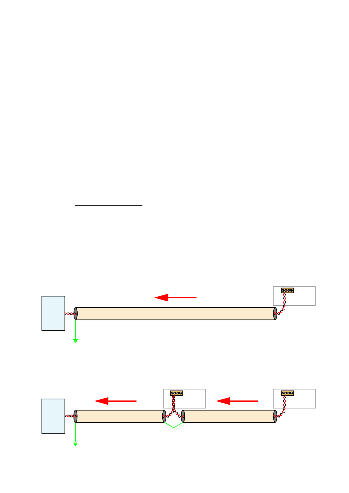
Isolation 250 VAC Optically isolated from input, logic, excitation, power,
alarms and serial communications ports
Response speed Derived from displayed value, which is updated 10 times per
second. Any filtering applied to the display will be applied to the
serial data output also.
Linearisation The analogue output is derived from the displayed value, so if your
display has a non linear response, and you are using the display’s
lineariser function, the output will follow the display directly.
Calendar/Clock option Accuracy better than +/- 10 seconds per month (DS3231SN)
Battery backup during power loss. Battery = CR1620 3V Lithium
Data strings:-
Specifications
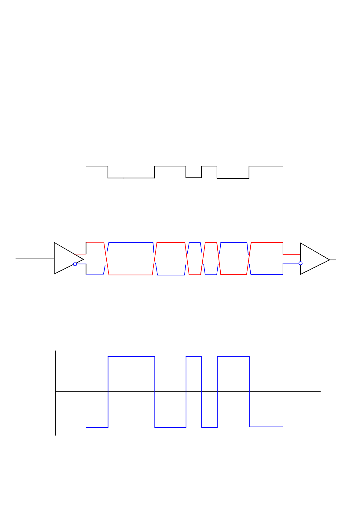
Protocol C1 – Continuous output (Enable line to common gives output)
Meter sends: 8 characters<CR><LF>
e.g.
20 20 20 20 20 2D 31 37 0D 0A (-17) decimal position = 0
20 20 20 20 2D 31 2E 36 0D 0A (-1.6) negative value
20 20 20 20 20 31 2E 38 0D 0A (+1.8) positive value
20 20 20 20 20 20 4F 52 0D 0A (OR) over range
20 20 20 20 20 20 55 52 0D 0A (UR) under range
Protocol H1 - GPS clock data format for use with ASR-GPS
Protocol P1 – Polled ASCII
Controller sends: <STX> ADDRH:ADDRL r <ETX> e.g. 02 46 37 72 03 ( to device F7)
Meter replies <STX> 8 characters <ETX>
e.g.
02 20 20 20 20 20 2D 31 37 03 (-17) decimal position = 0
02 20 20 20 20 2D 31 2E 36 03 (-1.6) negative value
02 20 20 20 20 20 31 2E 38 03 (+1.8) positive value
02 20 20 20 20 20 20 4F 52 03 (OR) over range
02 20 20 20 20 20 20 55 52 03 (UR) under range
Protocol P2 – Polled ASCII Modbus - See next page
When you have finished setting the meter, put the lockout switch in its ON position now, to
prevent your settings from being changed.