manuals.online logo
Brands
  1. Home
  2. •
  3. Brands
  4. •
  5. Bowflex
  6. •
  7. Home Gym
  8. •
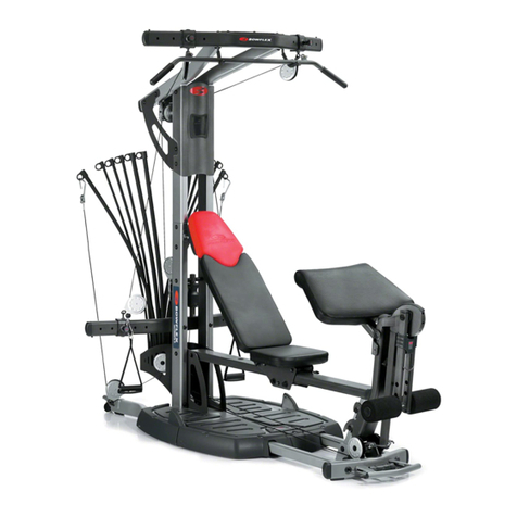
  9. Bowflex Bowflex Ultimate Machines User manual

Bowflex Bowflex Ultimate Machines User manual

Other Bowflex Home Gym manuals

Bowflex SelectTech 552i User manual

Bowflex

Bowflex SelectTech 552i User manual

Bowflex HOME GYM User manual

Bowflex

Bowflex HOME GYM User manual

Bowflex Revolution User manual

Bowflex

Bowflex Revolution User manual

Bowflex PR3000 User manual

Bowflex

Bowflex PR3000 User manual

Bowflex Bowflex Xtreme 2 SE User manual

Bowflex

Bowflex Bowflex Xtreme 2 SE User manual

Bowflex SelectTech 5.1 User manual

Bowflex

Bowflex SelectTech 5.1 User manual

Bowflex ULTIMATE 2 User manual

Bowflex

Bowflex ULTIMATE 2 User manual

Bowflex PR3000 User manual

Bowflex

Bowflex PR3000 User manual

Bowflex Xceed Plus User manual

Bowflex

Bowflex Xceed Plus User manual

Bowflex Motivator 2 User manual

Bowflex

Bowflex Motivator 2 User manual

Bowflex SelectTech 2080 User manual

Bowflex

Bowflex SelectTech 2080 User manual

Bowflex Xceed User manual

Bowflex

Bowflex Xceed User manual

Bowflex ULTIMATE 2 User manual

Bowflex

Bowflex ULTIMATE 2 User manual

Bowflex PR3000 User manual

Bowflex

Bowflex PR3000 User manual

Bowflex SelectTech 5.1 User manual

Bowflex

Bowflex SelectTech 5.1 User manual

Bowflex ULTIMATE User manual

Bowflex

Bowflex ULTIMATE User manual

Bowflex Classic User manual

Bowflex

Bowflex Classic User manual

Bowflex Bowflex Xtreme 2 SE User manual

Bowflex

Bowflex Bowflex Xtreme 2 SE User manual

Bowflex ElitePlus User manual

Bowflex

Bowflex ElitePlus User manual

Bowflex Motivator 2 User manual

Bowflex

Bowflex Motivator 2 User manual

Bowflex ElitePlus User manual

Bowflex

Bowflex ElitePlus User manual

Bowflex Bowflex Sport User manual

Bowflex

Bowflex Bowflex Sport User manual

Bowflex The BOWFLEX Xtreme2 User manual

Bowflex

Bowflex The BOWFLEX Xtreme2 User manual

Bowflex Bowflex Xtreme 2 SE User manual

Bowflex

Bowflex Bowflex Xtreme 2 SE User manual

Popular Home Gym manuals by other brands

T.D.S. 3501 Assembly instructions

T.D.S.

T.D.S. 3501 Assembly instructions

Body Solid EXM1950 Assembly instructions

Body Solid

Body Solid EXM1950 Assembly instructions

Horizon Fitness OXFORD 6 manual

Horizon Fitness

Horizon Fitness OXFORD 6 manual

Energetics Multi Trainer 5.1 owner's manual

Energetics

Energetics Multi Trainer 5.1 owner's manual

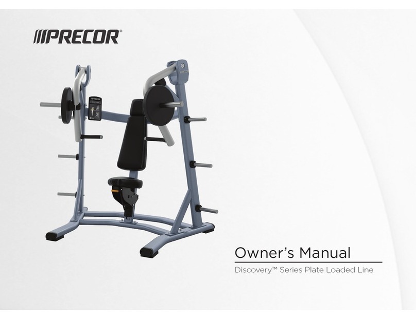
Precor Discovery Series owner's manual

Precor

Precor Discovery Series owner's manual

Matrix MG-PL Series Service manual

Matrix

Matrix MG-PL Series Service manual

Reebok Tbr2i Manuale d'istruzioni

Reebok

Reebok Tbr2i Manuale d'istruzioni

Weider 8300 Hard Drive manual

Weider

Weider 8300 Hard Drive manual

Pure Fitness 8526HE owner's manual

Pure Fitness

Pure Fitness 8526HE owner's manual

Weider 8700 I Bedienungsanleitung

Weider

Weider 8700 I Bedienungsanleitung

NordicTrack E8200 Competition Bench Bedienungsanleitung

NordicTrack

NordicTrack E8200 Competition Bench Bedienungsanleitung

Insportline RW600 user manual

Insportline

Insportline RW600 user manual

Weider WEMC10161 user manual

Weider

Weider WEMC10161 user manual

Body Solid GHYP-345 owner's manual

Body Solid

Body Solid GHYP-345 owner's manual

Evo TAHOE 5105 user manual

Evo

Evo TAHOE 5105 user manual

ParaBody 40 Assembly instructions

ParaBody

ParaBody 40 Assembly instructions

JLL Ventus Pro Air Power instruction manual

JLL

JLL Ventus Pro Air Power instruction manual

Trojan Colorado 370 user manual

Trojan

Trojan Colorado 370 user manual

manuals.online logo
manuals.online logoBrands
  • About & Mission
  • Contact us
  • Privacy Policy
  • Terms and Conditions

Copyright 2025 Manuals.Online. All Rights Reserved.

Assembly Manual
FOR THE BOWFLEX ULTIMATE
Includes Instructions for
Assembling
Bowflex Ultimate
Machines
®
Basic Assembly Principles
Here are a few basic assembly tips that can make your assembly of the Bowflex Ultimate quick and easy. By using
these principles, you can simplify the process and save yourself some extra time and effort.
1. When you are using a ratchet to tighten a locknut on a bolt, use a close-ended combination wrench to grip the
locknut. This will ensure that the locknut is fastened securely.
2. When you are having trouble placing a bolt between two separate pieces, you can get the bolt holes to line up by
gently lifting one of the pieces. You can also lift gently and look between the pieces for additional help guiding the
bolt through the holes.
3. You can make the assembly process go faster by gathering the pieces you need for each step prior to starting
the step.
4. As a general rule, and for all bolts and locknuts on your Bowflex Ultimate, turning toward the right will tighten,
turning toward the left will loosen. An easy way to remember this is by remembering the expression, "Lefty loosey,
righty tighty."
Tools You Will Need
You will need the following tools to complete the assembly of your Bowflex Ultimate. If you don't have these tools,
you can find them at any hardware or department store for a reasonable price.
•7/16" combination wrench
• 9/16" combination wrench
•An adjustable wrench
•A socket wrench set
•Phillips screw driver
• Flat blade screw driver
•Rubber mallet
• Utility Knife
• Scissors
Finished Photos
We've included a photograph at the end of each step reF resenting the end result of that step
in the assembly of your Bowflex Ultimate. If you have any doubt after finishing a step, refer
to these photos to see the accuracy of your assembly process.
This is m_exa,_ple of wh_t
the photos at fhe fisdsh qf
each step look like
Table of Contents
Bowflex Ultimate Parts Reference Guide ................................ Pages 4-6
Assembling the Bowflex Ultimate ............................................ Pages 7-13
Assembling the Bowflex Ultimate Lat Attachment ................ Pages 14-15
Assembling the Bowflex Ultimate Leg Attachment .............. Pages 16-19
Assembling the Bowflex Ultimate T-Bar .................................. Page 19
Adding extra Power Rods ............................................................ Page 20
Bowflex Ultimate Warranty Information .................................. Pages 21-23
Bowflex Ultimate 6-Week Satisfaction Guarantee .................. Page 24
BOWFLEX Ultimate °Parts Reference Guide
Rod Cap
Power Rods
Rod Hook
Cable >
Pul_y_
Snap
Hook Ring_
Rod Box\
Adjustable
Pulley
System
Hand Gripl_
Ankle Cuff
Squat
Platform
Squat
Pufley
Squat Bar _Foot Rest
Bench
Lat Tower Assembly
/_Bent Lat Bar
Special features unique to the
BOWFLEX ULTIMATE are the
special cable storage areas.
When the lat cables are not in
use they can be conveniently
tucked into the lat tower
assembly as shown to the top
left. In addition, the leg
extension cables can be
_._ clipped intothespecialclip
assemblylocatedunderthe
benchas shown in thepicture
tothe left.
Lower Lat Crown
Leg Extension Assembly
(if so equipped)
Leg Extension
Seat
Leg Extension
Rollers
Seat Raft Leg Extension
Pulley
Base Unit Assembly
Parts List
Item No. Qty. Part No. Description
1 1 10001 LOWER I_ATTOWER
2 1 10002 LEFT MAIN FRAME ASSEMBLY
3 1 10003 RIGHT MAIN FRAME ASSEMBLY
4 1 10004 SQUAT FRAME
5 1 10005 SQUAT PLATFORM
6 1 10011 ADJUSTABLE PULLEY SYSTEM
7 2 10012 ADJ, PULLEY SYST. BOLT SPACER
8 2 10074 ADJ, PULLEY SYST. LOCK KNOB
9 2 90177 PULLEY ASSEMBLY
10 1 10014 SEAT RAIL
11 1 10039 FOOT REST ASSEMBLY
13 1 10036 REAR LEG
14 1 10017 SEAT
21 1 10015 INCLINE BENCH REST
22 1 10016 INCLINE BENCH REST BACK
23 1 10049 ROD BOX w/RODS
24 1 10044 ROD BOX FRAME
25 1 10019 BENCH
26 1 10035 BENCH REST BRACKET
27 2 90215 ROD CABLE
32 2 10007 SQUAT CABLE
33 4 50334 SNAP HOOK
35 1 90650 48" BAR
36 2 10073 SQUAT STRAP
37 1 10075 LARGE THREADED KNOB
38 2 90134 HAND GRIP/ANKLE CUFF
Item No. Qty. Part No.
39 1 90640
41 390149
44 4 10182
45 3 10183
46 5 10103
48 3 10107
49 2 90193
51 2 90139
52 4 10125
53 1 10126
54 30 90138
55 6 90156
57 13 90196
58 1 90222
59 1 90217
73 2 10177
74 2 10178
75 8 10125
76 1 10201
Description
T-BAR w/STRAP
SCREW, 1/4" X 1-1/2" PHILLIPS HEAD
SCREW, #10 X 3/4" SELF TAPPING
SCREW, #10 X 1" SELF DRILLING
BOLT, 3/8" X3/4"
BOLT, 3/8" X 2"
BOLT, 3/8" X 2-1/2"
BOLT, 3/8" X3"
BOLT, 3/8" X 4-3/4"
BOLT, 3/8" X 5"
WASHER, 3/8"
WASHER, 1/4"
NUT, 3/8" NYLON LOCK NUT
RAIL END CAP
LEG PRESS BELT
REAR LEG BOLT KEEPER
LEG PRESS BOLT KEEPER
3/8" x 3/4' SQUARE HEAD BOLT
LOWER LAT CROWN
Item #: 1
110001
Des_
Ttem #: 7
Qty.: 2
Dart #: 10012
Descr: Adjustable
Pulley System
Ttem #: 14
Qty.: 1
Dart #: 10017
Descr: Seat
ttem #: 26
Oty.: 1
Dart #: 10035
Descr: Bench Rest
Bracket
Ttem #: 37
Qty.: 1
Dart #: 10075
Descr: Large
Threaded
Knob
Item #: 74
Qty.: 2
Part#: 10178
Descr: Leg Press
Bolt Keeper
Item #: 2
Qty.: 1
Part #: 10002
Oescr: Left Main
Frame
Assembly
Item #: 8
Qty.: 2
Part #: 10074
Descr: Adjustable
Pulley System
Lock Knob
Q
Item #: 21
Qty.: 1
Part #: 10015
Descr: Incline Bench
Rest
Item #: 27
Qty.: 2
Part #: 90215
Descr: Rod
Cable
Length: 43"
Item #: 38
Qty.: 2
Part #: 90134
Descr: Hand Grip/
Ankle Cuff
Item #: 76
Qty.: 1
Part #: 10201
Descr: Lower Lat
Crown
Item #: 3
Qty.: 1
Part #: 10003
Descr: Right Main
Frame
Item #: 9
Qty.: 2
Part #: 90177
Descr: Pulley
Assembly
Item #: 22
Qty.: 1
Part #: 10016
Descr: Incline Bench
Rest Back
Item #: 32
Qty.: 2
Part #: 10007
Descr: Squat
Cable
Length: 35"
Item #: 39
Qty.: 1
Part #: 90640
Descr: T-Bar
Item #: 4
Qty.: 1
Part #: 10004
Descr: Squat Frame
Item #: 10
Qty.: 1
Part #: 10014
Descr: Seat Raft
/
Item #: 23
Qty.: 1=[
Part #: 10049
Descr: Rod Box
w/Rods
Item #: 33
Qty.: 4
Part #: 50334
Descr: Snap Hook
Item#:58
Qty.: 1
Part_90222
Descr: Raft End Cap
Item #: 5
Qty.: 1
Part #: 10005
Descr: Squat
Platform
Item #: 11
Qty.: 1
Part #: 10039
Descr: Foot Rest
Item #: 24
Qty.: 1
Part #: 10044
Descr: Rod Box
Frame
Item #: 35
Qty.: 1
Part #: 90650
Item #: 59
Qty.: 1
Part #: 90217
Descr: Leg Press
Belt
Item #: 6
Qty.: 1
Part #: 10011
Descr: Adjustable
Pulley
Item #: 13
Qty.: 1
Part #: 10036
Descr: Rear Bench
Leg
%
Item #: 25
Item #: 36
Qty.: 2
Part #: 10073
Descr: Squat Strap
Item #: 73
Qty.: 2
Part #: 10177
Descr: Rear Leg Bolt
Keeper
02003 The N3utilus Group, hie ,V31/couvel: WA 98684 All rights reserved
Note: Drawings are actual size.
Serf Drilling
Screw
item #: 51
Qty.: 2
Part #: 90139
Descr: 3/8ol;X3"
Item #: 41
Qty.: 3
Part #: 90149
Descr: 1/4"X 1-1/2"
Phillips Head
Machine Screw
Item #: 46
Qty.: 5
Part #: 10103
Descr: 3/8" X 3/4"
Bolt
Item #: 53
Qty.: 1
Part #: 10126
Descr: 3/8" X 5"
Bolt
It_om #: 48
Item #: 52
Qty.: 4
Part #: 10125
Descr: 3/8" X 4-3/4"
Bolt
Item #: 49
_ltty.: 2
PaP rt #: 90193
escr: 3/8'lt' X 2-1/2"
Item #: 54
Qty.: 30
Part #: 90138
Descr: 3/8" Washer
Item #: 44
Qty.: 4
Part #: 10182
Descr: #10 X3/4"
Self Tapping
Screw
Item #: 55
Qty.: 6
Part #: 90156
Descr: 1/4"
Washer
Item #: 57
Qty.: 13
Part #: 90196
Descr: 3/8"
Nylon Lock
Item #: 75 Nut
Qty.: 8
Part #: 10125
Descr: 3/8" X3/4"
Square
Head Bolt
Step 1: LOWER MAIN FRAME ASSEMBLY
Locate the following for this step:
• Lower lat tower (Item #1)
• Left main frame (Item #2)
• Right main frame (Item #3)
• Two (2) 3/8X3" bolts (Item #51)
• Four (4) 3/8" washers (Item #54)
• Two (2) 3/8" nylon lock nuts (Item #51)
[] Place the left main frame (Item #2) into the
saddle bracket of the lower lat tower (Item #1)
as shown in Figure A.
[] Insert a 3/8"X3" bolt (Item #51) with a
washer on it through the appropriate holes,
place a 3/8" washer (Item #54) and then a 3/8"
nylon lock nut (Item #57) on the bolt, hand
tighten at this time.
[] Place the mating right hand side of the main
frame (Item #3) next to the left side of the
frame in the lower lat tower saddle bracket
(Item #t) and repeat step above.
Note: Hand tighten all bolts at this stage.
Figure A
I Components for this step
are in Box 2 & Box 4
Step 2: ADJUSTABLE PULLEY SYSTEM
Locate the following for this step:
•Adjustable Pulley System (Item #6) (_)
• Two (2) Adjustable Pulley System bolt spacers /
(Item #7, twist tied to Adjustable Pulley System) ]
•Two (2) 3/8"X2-1/2" bolts (Item #49)
•Two (2) 3/8"X3/4" bolts (Item #46)
•Four (4) 3/8" washers (Item #54)
• Two (2) Adjustable Pulley System lock knobs (Item #8) _4k_3r_ _
[] Remove twist ties from bolt spacers and slide Adjustable
Pulley System (Item #6) into main frame uprights as shown
in Figure B. _ .&
Note: The side with two large holes faces away from the machine. ®
[] Insert both 3/8"X2-1/2" bolts (Item #49) with 3/8" washers
(Item #54) into chest slide spacers and hand tighten into the back
of lower lat tower (Item #1) (NOTE: DO NOT OVERTIGHTEN)
Note: Inserting the top bolt first will help you align the parts.
[] Hand tighten the 3/8"X3/4" bolts (Item #46) with 3/8" washers
(Item #54) into the uprights of the main frame (Items #2&3).
Figure B
[] Make sure all the holes are properly aligned and screw the two
spring-loaded locking knob assemblies (Item #8) into the back side
of the Adjustable Pulley System as shown in figure B. Tighten the locking
knobs to the Adjustable Pulley System with an adjustable wrench.
Components
for this step
are in Box 4
Note: Do not unwrap the two pulley assemblies that are attached
to the Adjustable Pulley System at this time.
[] Securely tighten all bolts that have been placed on the unit up to this stage.
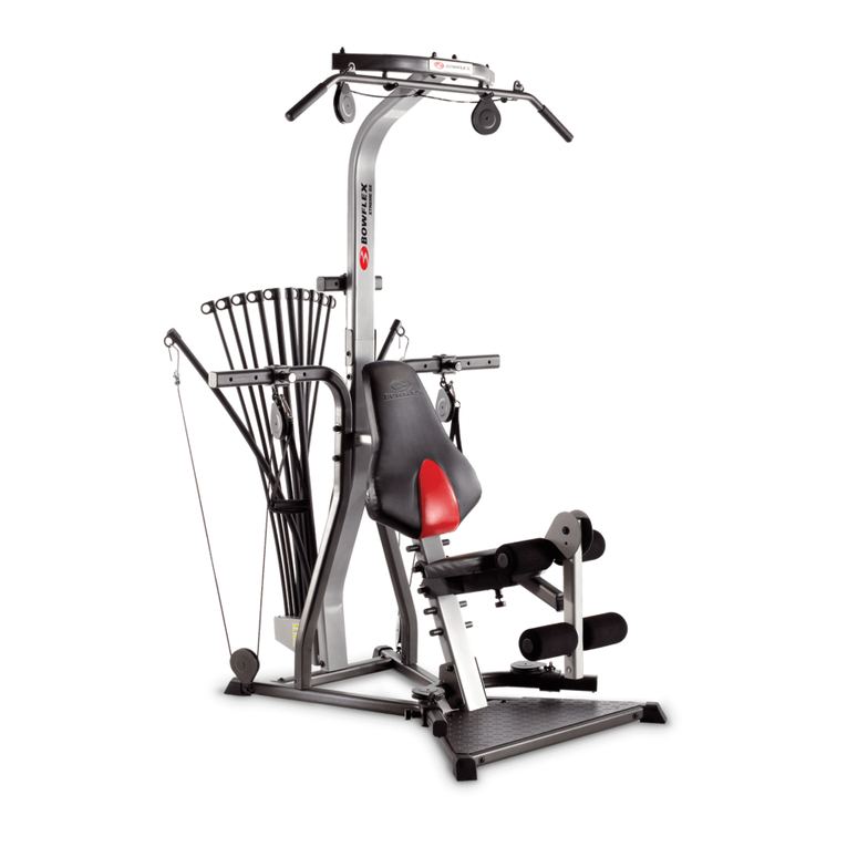
Unit appears like this
following this assembly step
Step 3: SQUAT PLATFORM & FRAME ASSEMBLY
Locate the following parts for this step:
• Large plastic squat platform (Item #5)
• Squat frame (Item #4)
• Four (4) 3/8"X4-3/4" bolts (Item #52)
• Six (6) 3/8" washers (Item #54)
• Two 3/8" lock nuts (Item #57)
[] Align the holes in the main frame (Items #2&3)
and the squat frame (Item #4) and insert the four
bolts with washers on them into the four holes as
shown in Figure C. De not tighten at this time.
[] Slide the squat platform onto the frame assembly
by aligning the notches on the sides with the bolts
on the frame assembly. Make sure the platform goes
behind the washers.
[] Place washers and nuts on the inside of the two
forward bolts. Apply downward pressure to the
platform by kneeling on it and tighten all the bolts.
Note: The two rear bolts do not require the use
of a washer or lock nut on the inside of the
assembly.
Figure C
Figure C2
Components for this step
are in Box 2 and Box 4
Step 4: BOLT KEEPER INSERTION
Locate the following parts for this step:
• Seat rail (Item #10)
•Eight (8) 3/8" X 3/4" Square Head Bolts (Item #75)
•Two (2) Rear Leg Bolt Keepers (Item #73)
•Two (2) Leg Press Bolt Keepers (Item #74)
[] Take two 3/8" x 3/4" bolts (Item #75) and place them
through holes in a Rear Leg Bolt Keeper (Item #73), Take that
assembly and slide it into a Seat Rail (Item #10) channel,
starting on the end closest to the warning label, as shown in
Figure E. Line up the end of the bolt keeper with the end of the
rail. Repeat for the other Rear Leg Bolt Keeper.
[] Go to the other end of the Seat Rail. Take two bolts (Item
#75) and place them through holes in a Leg Press Bolt Keeper
(Item #74). With the bolt-end of the bolt keeper pointed
toward the seat rail, slide that assembly into a channel as
shown in Figure El. You may need to remove the twist tie
holding the rail spacer blocks in place to slide the bolt keepers
into the rail.
Note: Please use caution when inserting bolt keepers. Edges
may be sharp.
Figure E
Figure E1
Components for this step I
are in Box3 and Box4 I
Step 5: REAR LEG
Locate the following parts for this step:
•Rear leg (Item #13)
•Seat rail (Item #10)
•Four (4) 3/8" nylon lock nuts (Item #57)
•Four (4) 3/8" washers (Item #54)
[] Find the four bolts in the channels on the bottom of the seat
rail assembly closest to the warning sticker. Place the rear leg
mounting bracket (Item #13) over the four bolts. Make sure
the edge of the bracket is flush with the end of the rail. Place
four (4) 3/8" washers (Item #54) and four (4)3/8" nylon lock
nuts (Item #57) on the bolts as shown in figure E2 and tighten.
Figure E2
Components for this
step are in Box 4
Unit appears like
this following this
assembly step
Step 6: FOOT REST
Locate the following parts for this step:
• Leg press assembly (Item #11)
• Seat rail (Item #10)
• Four (4) 3/8" nylon lock nuts (Item #57)
• Four (4) 3/8" washers (Item #54)
[] Find the four bolts in the channels on the bottom
of the seat rail assembly that are closest to the
threaded hole. Place the leg press assembly (Item
#11) on the four bolts. Place four (4)3/8" washers
(Item #54) and four (4) 3/8" nylon lock nuts (Item
#57) on the bolts as shown in Figure E3. Make sure
the ends of the bolt keepers holding the leg press
bolts in place are flush with the end of the seat rail.
This will determine the final alignment of the leg
press assembly.
I Components for this
step are in Box 4
Figure E3
assembly step
Step 7: SEAT RAIL INSTALLATION
The following parts are required for this step:
• Seat Rail {Item #10)
• One (1) 3/8"X5" bolt {Item #53)
• Two (2) 3/8" washers {Item #54)
• One (1) 3/8" nylon lock nut {Item #57)
• Large Knob {Item #37)
[] If you have not already done so, remove
the twist-tie that holds the rail spacer blocks
and tube in place on the side of the seat rail.
[] Slide the seat rail, right side up, into the
main frame and rest it on the cross bar as
shown in Figure F.
[] Slide the 3/8"X5" bolt {Item #53) with a
washer through main frame and seat rail as
shown in Figure F. Place 3/8" washer {Item
#54) and 3/8" nylon lock nut
(Item #57) on bolt and tighten.
[] Place the large knob (Item #37) into the
hole in the top of the frame and tighten.
Figure F
Step 8: SEAT INSTALLATION
Locate the following parts for this step:
•Seat Assembly
[] Pull out and lock the pin on the left side of the seat
assembly and slide the seat onto the rail as shown in
Figure G.
Figure G
Components for this I
step are in Box 3 I
Unit appears
like this
following this
assembly step