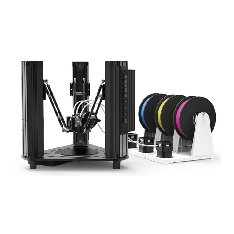
Box3d box3d 500 Instruction Manual

1
Box3d building instructions
For box3d 500 and box3d XL
(version may 2018)
Box3d B.V.
Staalweg 1
2612KK Delft
Netherlands
www.box3d.eu

2
Safety instructions
Assembling your box3d requires some experience with technical tools and common sense. These
building instructions will guide you through the process of assembling your box3d 500 or box3d XL. We
have made this process as easily and accessible as possible. However, we cannot be responsible for any
harm during assembly or operation of box3d. Make sure you are confident at each step, or ask a more
experienced builder for help.
Box3d operates at 12V, so the user should never be involved with high voltage. However, current can
still be dangerous, so be careful at all times. Never plug in the power adapter into box3d during these
assembly.
Box3d includes a fan which regulates the temperature inside. Depending on the settings in the
controller, the fan can turn very fast with high power. So be careful not to touch the fan when box3d is
on.
We do not recommend to leave your printer and box3d running unattended.

3
Contents
Parts list.........................................................................................................................................................4
Print your parts .............................................................................................................................................9
Pre-assembly...............................................................................................................................................10
Foam preparation .......................................................................................................................................12
Top panel foam.......................................................................................................................................13
Air inlet cutout........................................................................................................................................13
Panel 1 (right panel)....................................................................................................................................14
Panel 2 (left panel)......................................................................................................................................15
Panel 3 (rear panel).....................................................................................................................................16
Panel 4 (mid panel) .....................................................................................................................................17
Panel 5 (front panel) ...................................................................................................................................18
Connecting panels.......................................................................................................................................19
Installing the door.......................................................................................................................................26
Electronics...................................................................................................................................................30
Paste top foam............................................................................................................................................36
Paste sidewall foam ....................................................................................................................................37
Close the top...............................................................................................................................................38

4
Parts list
#
Parts
Qty 500
Qty XL
A
Inbus M4x10
87
87
B
Nut M4
93
93
C
Magnet + magnet ring
1
1
Inbus M4x16
12
12
Inbus M4x50
2
2
Washer M4
2
2
Washer M4 plastic
4
4
Metal screw M3x12
1
1
Washer M3
1
1
Nut M3
1
1

5
D
Hinge
2
2
Inbus wrench M4
1
1
Inbus wrench M5
1
1
Inbus M5x16
4
4
Inbus M5x20
4
4
Washer M5
14
14
Nut M5
8
8
Handle with 2 screws
3
3

6
E
Controller
1
1
Switch
1
1
Power connector
1
1
Sensor
1
1
USB cable
1
1
Power cable
(red/black)
1
1
Switch cable
1
1
F
Gland
1
1
O-ring
1
1
Tiewrap
1
1
G
Carbon filters
(optional)
2
2

7
Seperate
parts
Power adapter
1
1
Fan
1
1
Foam sheets
4
6
Window
1
1
Rubber seal
1
1
Front panel
1
1
Back panel
1
1

8
Left panel
1
1
Right panel
1
1
Bottom panel
1
1
Top outside panel
1
1
Top inside panel
1
1
Hepa filter
(optional)
1
1
Cutting template
1
1

9
Print your parts
-Go to box3d.eu to download the STL files for box3d.
-Print all files as shown in the table below. The “grouped” folder contains parts #1 - #6 in the
correct quantities, which might make it easier to print.
#
Qty
3D printing remarks
1
corner
12
No support needed
2
insert 2
12
No support needed
3
insert 3
29
No support needed
4
side connector
15
No support needed
5
magnet holder
1
No support needed
6
side connector high
4
No support needed
7
hinge spacer
2
No support needed
8
controller spacer
4
No support needed
9
fan outlet
1
Use support material
Optional
tube connector
120mm
1
No support needed
Optional
tube connector
100mm
1
No support needed
Optional
(filter
version)
filter housing + filter
clip
1
No support needed

10
Pre-assembly
-Fill every #1 with 3 M4 nuts, and lock them with #2. (12x #1, 12x #2, 36x nut M4)
-Fill every #4 with 2 M4 nuts, and lock them with #3. (15x #4, 15x #3, 30x nut M4)
-Insert 3 M4 nuts in #5, and lock them with #3. (1x #5, 2x #3, 3x nut M4)
-Insert the magnet in #5. A hard push is necessary to fully insert the magnet.

11
-Fill very #6 with 3 M4 nuts, and lock them with #3. (4x #6, 8x #3, 12x nut M4)
-Insert 4 nuts in the fan outlet, and lock them with #3. (1x fan outlet, 4x #3, 4x nut M4)
-Only if you have the filter version: Attach the filter clip to the filter housing, with 2x M4x10 inbus
screws and 2x M4 nuts.

12
Foam preparation
Box3d 500 contains the following foam panels:
Note: for box3d XL, Side S and Side L are divided in 2 or 3 pieces.
Note: For box3d 500, Side S and Side L need to be shortened by 8cm. Use scissors to cut the panels as
shown below:
Side S
Side L
Top S
Top L

13
Top panel foam
Place the top inside panel on top of the Top L foam panel. Align the sides and bottom as in the figure
below. The blue dotted line represents the top L foam panel. Trace the contours of the holes with a
marker. Use the template to trace the contours of the filter housing with a marker. (this step can be
skipped for box3d without filter. Without this step future upgrade to HEPA filter is not possible,
therefore we suggest everyone to do this step).
Use a scissor to cut out the shaded areas.
Air inlet cutout
Take the Side L foam panel and draw the air outlet of 170mm x 80mm at [835mm for box3d 500,
1020mm for box3d XL] from the right end of the panel. Use scissors to cut out the air inlet. Do not
throw away the cut part.

14
Panel 1 (right panel)
-Mount the corner pieces (#1+#2, and #4+#3) on places marked with an “X”. Use M4x10 inbus
screws. The shape of the “x” shows the orientation of the part.
o4x #1+#2
o6x #4+#3
o10x inbus screw M4x10
o1x Right panel
+

15
Panel 2 (left panel)
-Mount the corner pieces (#1+#2, and #4+#3) on places marked with an “X”. Use M4x10 inbus
screws. The shape of the “x” shows the orientation of the part.
o4x #1+#2
o7x #4+#3
o11x inbus screw M4x10
o1x Left panel
+

16
Panel 3 (rear panel)
-Mount one corner piece (#4+#3) with an M4x10 inbus screw. The shape of the “x” shows the
orientation of the part.
o1x #4+#3
o1x inbus screw M4x10
o1x Rear panel
+

17
Panel 4 (top inside panel)
-Mount the corner pieces (#1+#2) on the four corners, and mount the four high corner pieces
(#6+#3) on the four remaining “X” spots. Note: make sure the orientation of the high corner
pieces is correct (see picture)
o4x #1+#2
o4x #6+#3
o8x inbus screw M4x10
o1x top inside panel
+

18
Panel 5 (front panel)
-Mount the piece with the magnet on the large “x”, and a corner piece (#4+#3) on the small “X”.
o1x #5+#3
o1x #4+#3
o3x inbus screw m4x10
o1x Front panel
+

19
Connecting panels
-Connect the left panel to the back panel with 5x M4x10 inbus screws. (make sure the shapes are
aligned.
o5x inbus screw M4x10
o1x left panel
o1x back panel
+
+

20
-Connect the top inside panel to the back and left panel with 6x M4x10 inbus screws. (make sure
the shapes are aligned)
o6x M4x10 inbus screws
o1x top inside panel
o1x Back+Left panel
+
+
This manual suits for next models
1
Table of contents
