manuals.online logo
Brands
  1. Home
  2. •
  3. Brands
  4. •
  5. BOXLIGHT
  6. •
  7. Educational Equipment
  8. •
  9. BOXLIGHT Mimio MyBot User manual

BOXLIGHT Mimio MyBot User manual

Other manuals for Mimio MyBot

1

Other BOXLIGHT Educational Equipment manuals

BOXLIGHT frontrow Juno User manual

BOXLIGHT

BOXLIGHT frontrow Juno User manual

BOXLIGHT MimioFrame Manual

BOXLIGHT

BOXLIGHT MimioFrame Manual

BOXLIGHT frontrow ezRoom User manual

BOXLIGHT

BOXLIGHT frontrow ezRoom User manual

BOXLIGHT MimioClarity Manual

BOXLIGHT

BOXLIGHT MimioClarity Manual

Popular Educational Equipment manuals by other brands

DISCOVER talking pen user guide

DISCOVER

DISCOVER talking pen user guide

pitsco Smart Buddies 45895 quick start guide

pitsco

pitsco Smart Buddies 45895 quick start guide

RS 3.5 quick start guide

RS

RS 3.5 quick start guide

Quanser QNET 2.0 quick start guide

Quanser

Quanser QNET 2.0 quick start guide

CAE Healthcare METIman user guide

CAE Healthcare

CAE Healthcare METIman user guide

Turning Technologies Pulse quick start guide

Turning Technologies

Turning Technologies Pulse quick start guide

TruCorp AirSim user manual

TruCorp

TruCorp AirSim user manual

LION R.A.C.E. STATION user manual

LION

LION R.A.C.E. STATION user manual

jp.ik LEAPW505 user guide

jp.ik

jp.ik LEAPW505 user guide

laerdal ASL 5000 Lung Solution for SimMan Quick setup guide

laerdal

laerdal ASL 5000 Lung Solution for SimMan Quick setup guide

Rompa GYMTOP 20143 manual

Rompa

Rompa GYMTOP 20143 manual

ScienTECH 2261 Product tutorial

ScienTECH

ScienTECH 2261 Product tutorial

Quanser 6 DOF Hexapod Laboratory guide

Quanser

Quanser 6 DOF Hexapod Laboratory guide

Surefire Flying Model Rocket Kit How to use

Surefire

Surefire Flying Model Rocket Kit How to use

ACROME myCONTROL STEWART PRO user manual

ACROME

ACROME myCONTROL STEWART PRO user manual

SmartMan Baby Manikin manual

SmartMan

SmartMan Baby Manikin manual

Nasco Life/form LF03840U instruction manual

Nasco

Nasco Life/form LF03840U instruction manual

Pitsco Education BUILDERSPACES SPACEPORT Assembly instructions

Pitsco Education

Pitsco Education BUILDERSPACES SPACEPORT Assembly instructions

manuals.online logo
manuals.online logoBrands
  • About & Mission
  • Contact us
  • Privacy Policy
  • Terms and Conditions

Copyright 2025 Manuals.Online. All Rights Reserved.

Includes Assembly Steps for Planetary Explorer Kits
For kits supplied with BLACK wheels
MyBot Base Kit Assembly Instructions v1.4a Page 2 of 18
(For kits supplied with black wheels)
MyBot Base Kit | Assembly Guide
Special Note for Planetary Explorer Kits
These instructions include additional steps to support Planetary Explorer Kit assembly
as well as how to upgrade a base kit with the Planetary Explorer sensors.
Copyright 2018-2022, Boxlight Robotics, All Rights Reserved
No part of this document may be copied, published in print or shared online or otherwise publicly released without the express written
consent of Boxlight Robotics.
Note: Specifications listed are subject to change without notice.
MyBot Base Kit Assembly Instructions v1.4a Page 3 of 18
(For kits supplied with black wheels)
MyBot Base Kit | Assembly Guide
Illustrated List of Components
x2
04-0305
3x5 Gusset Plate
(Used together)
x1 x1
08-0007 11-3204
4mm Axle Hub M4 Set Screw
x2
13-0134
DC Motor, 6v, 185RPM
x1
04-0309
3x9 Gusset Plate
x2
08-0020
4mm D-Shaft Axle Collar
x2
45-1025
Motor Mount
x1
05-0303
3x3 Flanged Plate
x1
10-0052
4mm x 52mm D-Shaft
x2
45-1020
Motor Mount Spacer
x1
05-0513
5x13 Flanged Plate
x8
09-0005
32mm M4 Threaded Standoff
x2
45-1410
72mm Wheel
x1
06-1319
13x19 Flanged Plate
x1
45-2100
19mm Ball Caster
x1
45-0300
6v Battery Clip
MyBot Base Kit Assembly Instructions v1.4a Page 4 of 18
(For kits supplied with black wheels)
MyBot Base Kit | Assembly Guide
Illustrated List of Components
x6
11-4116
M4 x 16mm Screw
x14
11-6001
Quick Connect, Short (black)
x1
45-2005
Integrating Gyro
x28
11-4108
M4 x 8mm Screw
x6
11-6002
Quick Connect, Medium (white)
x1
45-2006
Optical Distance Sensor
x4
11-3106
M3 x 6mm Phillips Head Screw
x20
11-4501 –or –11-4502
M4 Hex Nut
x1
45-2007
Touch Sensor
x1
50-0076
Tool Kit (may differ from illustration)
x1
15-0016
Storage Box (for spare fasteners & parts)
x1
45-1300
6v Battery Pack (NiMH)
x1
52-2022
Fusion Controller Kit
Fusion Controller Module (from kit)
x1
45-1301
Battery Charger
- or -
MyBot Base Kit Assembly Instructions v1.4a Page 5 of 18
(For kits supplied with black wheels)
MyBot Base Kit | Assembly Guide
STEP 1 –Preparing the Base Plate:
1. Using four (4) M4 x 8mm Screws, attach four (4) M4x32mm
Standoffs to the 13x19 Flanged Plate as shown.
a. Insure that the standoffs and the flanges on the plate
are on the same side.
b. There should be one empty row of holes between the
flanged edge and the standoffs.
STEP 2 –Attaching the Battery Clip:
2. Flip the flange over and attach the battery clip using two
M4 Hex Nuts and two M4 x 8mm Screws..
a. Make sure the nuts are on the same side as the
battery clip.
b. Secure the battery clip only on the end with the large
circular hole through the flanged plate. The other end
is not attached with screws and nuts.
STEP 3 –Preparing to Attach the Ball Caster:
3. Using four (4) M4 x 8mm Screws, attach four (4) M4x32mm
Standoffs to the 13x19 Flanged Plate as shown.
a. Insure that the standoffs are on the same side as the
battery clip.
b. Do not fully tighten the screws until after Step 4. This
will make lining the holes up easier.
1x
4x
4x (8mm)
2x
2x (8mm)
4x
4x (8mm)
1x
MyBot Base Kit Assembly Instructions v1.4a Page 6 of 18
(For kits supplied with black wheels)
MyBot Base Kit | Assembly Guide
STEP 4 –Attaching the Ball Caster:
4. Using four (4) M4 x 8mm Screws, attach the 19mm Ball
Caster to the ends of the standoffs.
a. Do not fully tighten the screws until all of them are in
place and the Ball Caster is straight and even.
b. Fully tighten all 8 screws beginning with those holding
the Ball Caster to the standoffs, then the ones holding
the standoffs to the Flanged Plate.
STEP 5 –Assembling the “Cow Catcher”:
5. Using two (2) of the Small Quick Connects on each side,
attach a 3x5 Gusset Plate to each end of the 5x13 Flanged
Plate as shown.
a. Insert the quick connect through the hole in the
Gusset Plate and the Flanged Plate so that the plates
are together, then firmly push the head of the quick
connect to lock the pieces in place.
b. The head of the quick connect will be flush against the
plate when fully engaged.
STEP 6 –Attaching the “Cow Catcher”:
6. Align the assembled Cow Catcher at the front of the robot
as shown and attach it with two (2) quick connects on each
side.
a. Be certain that there is one empty hole on the gusset
plate that extends beyond the flange on the robot’s
base plate.
4x (8mm)
1x
2x
4x
1x
4x
From Step 5
Why is this called a “Cow Catcher”?
In the early days of rail transportation, collision with an object on the tracks (like a stray cow wandering around on the plains and prairies) could do a lot
of damage to the train. To help avoid collisions, the engines would have a wedge-shaped piece on the front to lift and push an object aside.
While it is unlikely that your robot will encounter a cow laying it its path, the “cow catcher” helps prevent the
robot from running over other objects that might be in the way and could cause damage.
The cow catcher was invented in 1838 by Charles Babbage. He was a mathematician, inventor,
design engineer, and originated the concept of a digital programmable computer –just like the computer
that powers your MyBot Robot! He is considered by some to be the father of the computer
MyBot Base Kit Assembly Instructions v1.4a Page 7 of 18
(For kits supplied with black wheels)
MyBot Base Kit | Assembly Guide
STEP 7 –Assembling the Touch Sensor “Plunger” – Part 1:
The Plunger extends the reach of the touch sensor in front of
the robot. An exploded image is shown here. These
instructions will build the plunger in steps.
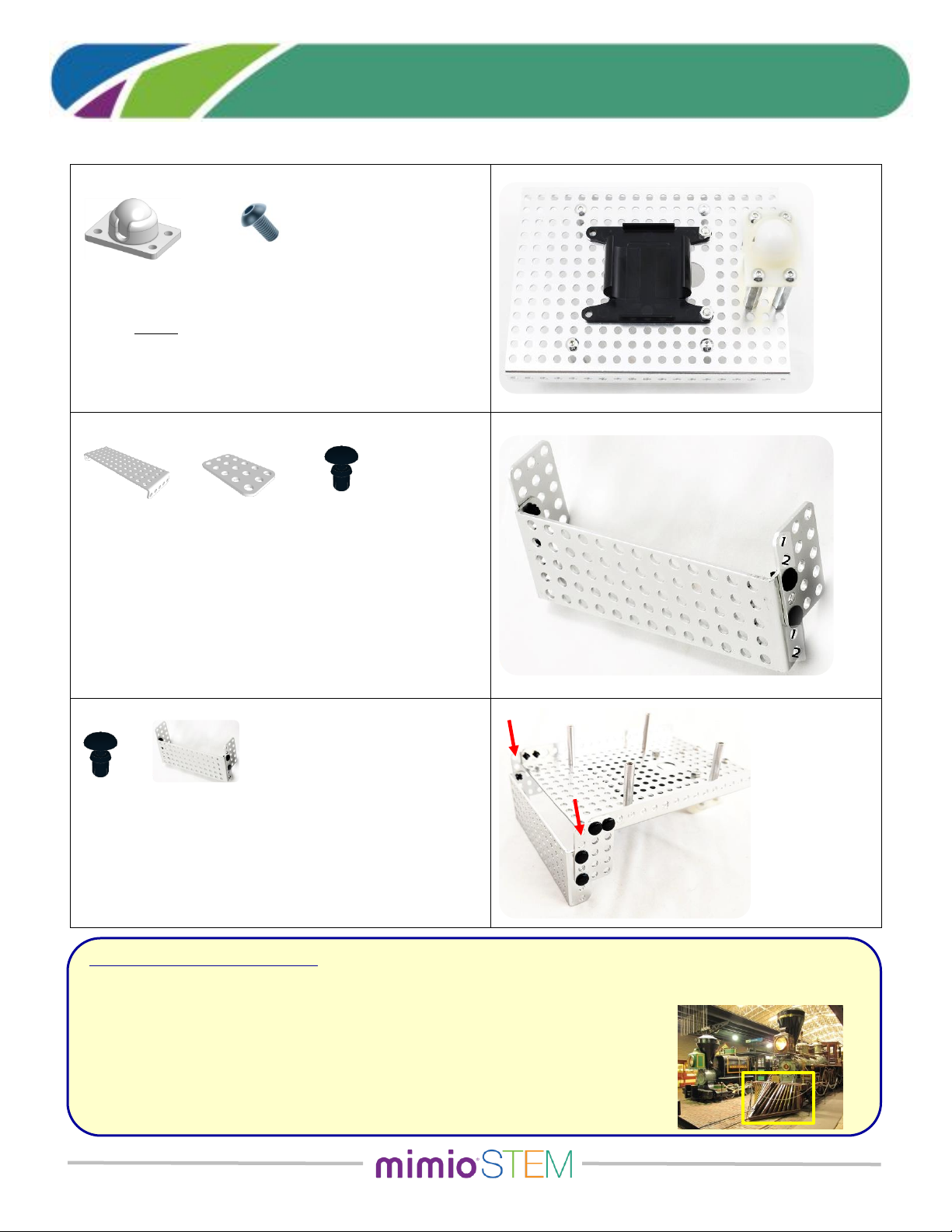
7. Begin by threading the Set Screw into the Axle Hub.
Since the set screw is so small, it helps to put the set
screw onto your allen wrench, then line it up with the
hole on the side of the hub and screw it in about half-
way. Confirm that the shaft slides easily through the
center hole of the hub.
a. Next, place the Axle Hub on a flat surface with the
‘dimple’ facing up (as shown in the parts drawing
above).
b. Insert the axle into the center hole of the hub so
that it is standing straight up with the flat of the
shaft facing the set screw.
c. Without lifting or tilting, tighten the set screw to
securely hold the shaft in the axle hub.
d. Inspect the flat end of the Axle Hub. The shaft
should be flush with the surface
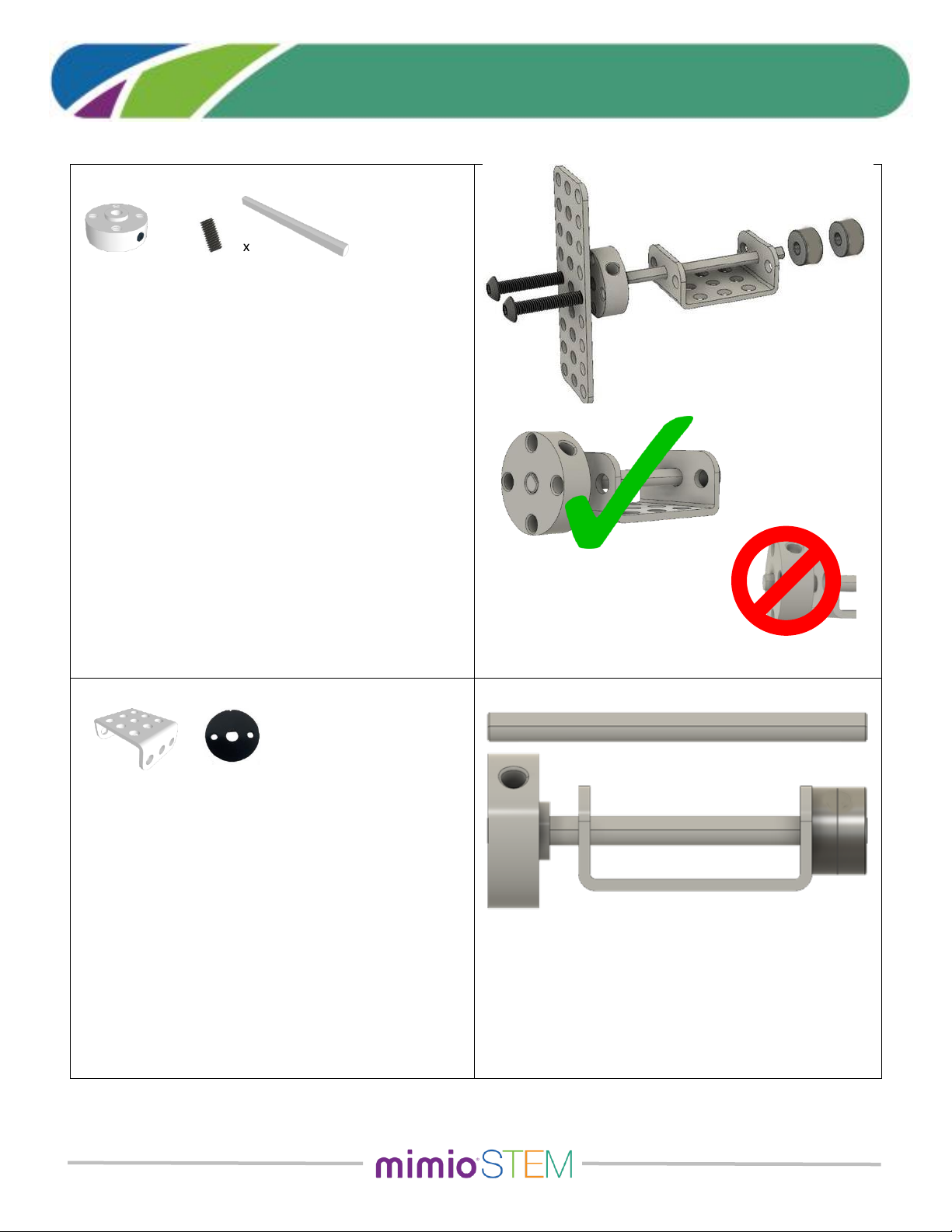
STEP 8 –Assembling the Touch Sensor “Plunger” – Part 2:
When complete, the length of this plunger will be the same as
the length of the shaft by itself.
8. With the Axle Hub still on the table, slide the 3x3
Flanged Plate onto the shaft using the center holes on
the two flanges.
a. Align one of the Axle Collars with the D-shape of the
shaft and push the Collar onto the shaft. You may
find that using a small hammer to tap the collar
down will help. (Alternately, using a quarter-sized
coin between the collar and your hand will help you
apply more force to the collar.) Push the Collar so it
is flush with the end of the shaft.
b. Using the same procedure, press the second Collar
onto the end of the shaft and press it down so it is
flush with the end of the shaft.
1x
1x
1x
1x
2x
MyBot Base Kit Assembly Instructions v1.4a Page 8 of 18
(For kits supplied with black wheels)
MyBot Base Kit | Assembly Guide
STEP 9 –Assembling the Touch Sensor “Plunger” – Part 3:
9. Using two (2) M4 x 16mm screws, attach a 3x9 Gusset
Plate to the front of the Axle Hub.
a. The screws will pass through the holes in the 3x3
Flanged Plate and prevent the shaft from rotating.
NOTE: For Planetary Exploration Kits, please use Step P9
on page 15.
STEP 10 –Attaching the Touch Sensor Plunger:
10. Using two (2) of the Small Quick Connects on each side,
attach the Touch Sensor Plunger to the top-front of the
robot’s base plate.
a. As shown, the Flanged Plate is centered on the base
plate with five (5) empty holes on each side.
b. Note that the Flanged Plate hangs off the edge.
STEP 11 –Mounting the Touch Sensor:
11. The Touch Sensor is mounted using two (2) Medium
Quick Connects. For this sensor, the quick connects
must come up from the bottom of the base plate.
a. The sensor is positioned so that the plunger presses
the red button on the front of the sensor.
b. The sensor cannot be perfectly centered so place it
between the standoffs as shown, with two (2)
empty holes on one side and three (3) empty holes
on the other.
2x
1x
1x
2x (16mm)
1x
2x
1
2
3
1
2
MyBot Base Kit Assembly Instructions v1.4a Page 9 of 18
(For kits supplied with black wheels)
MyBot Base Kit | Assembly Guide
STEP 12 –Mounting the Integrating Gyro:
12. The Integrating Gyro is mounted using two (2) of the
Medium Quick Connects. These are inserted from the
top of the robot’s base plate.
a. The gyro can be mounted as shown or placed so
that the back of the sensor is against the flange.
STEP 13 –Mounting the Optical Distance Sensor:
13. The Optical Distance Sensor is mounted using two (2) of
the Medium Quick Connects to the front of the Cow
Catcher.
a. Align the end of the sensor with the bottom of the
Cow Catcher plate and attach using the Quick
Connects
b. Make sure the sensor does not interfere with the
motion of the plunger.
In this downward facing position, the Optical Distance sensor
can be used for line-following activities.
The sensor can also be mounted facing forward on the top of the
base plate to detect objects in the robot’s path.
NOTE: For Planetary Exploration Kits, please use Steps
P13.1, P13.2, and P13.3 starting on page 17.
STEP 14 –Preparing the Motors:
14. Using two (2) M3 x 6mm screws, attach a motor to each
motor mounting plate.
a. Use the ‘vertical’ holes only. The ‘horizontal’ holes
do not line up with the motor.
b. Insure that the motor oriented so that the wire is on
the top (at the narrow end) of the motor mount.
c. Slide the cable-tie holding the wire to the motor so
that the latching end of the cable-tie is on a side,
and is not at the bottom (ie: towards the wide end
of the motor mount).
1x
2x
2x
4x (M3 x 6mm)
1x
2x
2x
MyBot Base Kit Assembly Instructions v1.4a Page 10 of 18
(For kits supplied with black wheels)
MyBot Base Kit | Assembly Guide
STEP 15 –Mounting the Motors on the Robot:
15. Using a Motor Mount Spacer between the Motor Mount
and the side flange of the robot’s base plate, attach a
motor to each side of the robot and secure with two (2)
M4 x 16mm screws and Hex Nuts.
a. The motors are mounted directly behind the cow
catcher’s 3x5 Gusset Plates. Do not leave any empty
holes between the plates and the motor.
STEP 16 –Attaching the wheels
16. The wheels are pressed onto the motor shafts using the
same technique used to press the Axle Collars on to the
Plunger shaft.
a. With the wheel hub screws to the outside, align the
D-shaped cutout to the motor’s axle and press it
onto the shaft.
b. It may be easier to place the wheel on a table and
push the robot/motor down into the wheel.
c. The motor shaft should be flush with the wheel hub
(or extend slightly) when properly installed.
STEP 17 –Install the Battery and Prepare for Wiring:
17. Insuring that the battery wire is towards the back of the
robot, snap the battery pack into the battery clip on the
bottom side of the robot.
a. Route the wires from the motors and the battery
pack through the large hole and to the top-side of
the robot.
b. Arrange the wires neatly along the bottom of the
robot; using some small twist-ties or cable ties to
help keep them in place.
2x
4x (16mm)
2x
1x
2x
4x