Boyertown Furnace PurePro Energy Manager PRO 6000Z User manual

INSTALLATION INSTRUCTIONS
Energy Manager
PRO6000Z
Keep these instructions with the boiler at all times.
BOYERTOWNFURNACECO.
PO Box 100
BOYERTOWN, PA 19512
1-610-369-1450
www.boyertownfurnace.com
1-03-22
2
Danger
Warning
Caution
Notice
Warning
Be Aware of Hazard Definitions
Denotes presence of a hazard which, if ignored, will result in severe personal injury,
death or property damage
Denotes presence of a hazard which, if ignored could result in severe personal injury,
death or substantial property damage.
Denotes the presence of a hazard, which if ignored, could result in minor personal
injury or property damage
Intended to bring attention to information, but not related to personal injury or property
damage.
This equipment must be installed, adjusted, serviced and started only by a qualified service
agency – an individual or agency, licensed and experienced with all codes and ordinances, and who is
responsible for the installation and adjustment of the equipment. The installation must comply with all
local codes and ordinances and with the latest revision of the National Fire Protection Standard for Oil
Burning Equipment, NFPA 31.
Read all instructions before proceeding. Follow all instructions completely. Failure to follow these
instructions could result in equipment malfunction causing severe personal injury, death or substantial
property damage.
Do not alter this kit or the boiler in any way. The manufacturer will not be liable for any damage
resulting from changes made in the field to the boiler or its components or from improper installation.
Failure to comply could result in severe personal injury, death, or substantial property damage.
Your oil fired boiler is designed to burn No. 1 and No. 2 heating oil only. Never use gasoline or a
mixture of gasoline and oil.
Do not store gasoline or other flammable vapors and liquids in the vicinity of this or any other appliance.
The area around the boiler should be kept free and clear of combustible materials.
Never burn garbage or refuse in your boiler.
Never try to ignite oil by tossing burning papers or other material into your boiler.
Do not attempt to start the burner when excess oil has accumulated or the boiler is full of vapors.
Do not operate boiler if the heat exchanger is damaged.
Do not jumper, attempt to bypass or override any of the safety limit controls.
Do not use this boiler if any part has been under water. Immediately call a qualified service technician to
inspect the boiler and replace any part of the boiler, control system or burner that has been under water.
All installations must conform to the requirements of the authority having jurisdiction. Such applicable
requirements take precedence over the general instructions of this manual.
Where required by the authority having jurisdiction, the installation must conform to the American
Society of Mechanical Engineers Safety Code for Controls and Safety Devices for Automatically Fired
Boilers, ANSI/ASME CSD-1.
Concealed Damage- If you discover damage to the burner, boiler or controls during
unpacking, notify the carrier at once and file the appropriate claim. When calling or writing about the
boiler please have the following information available: The boiler model number and serial number.
Danger
Notice

3
Table of Contents
Specifications 4
Energy Manager Pro 6000Z Features 4
Installing the Energy Manager Pro 6000Z………………...………………………………4
Internal Components………………………………………………………………………6
HydroStat Bezel……………………………………………………………………………7
Caleffi Zone Board……………………………………………………………………..….7
Caleffi Settings and Connections………………………………….…………….…..…….8
Electrical Wiring………………………………………………………….………………11
Internal Wiring………………………………………………………...……………12
Field Connections Zone Valves with Plug’n Go Plus……………….………...……13
Field Connections Zone Valves including Indirect Tank…………….…..…………14
Field Connections Indirect with Circulator…………………………………………15
Optional Accessory Kits…………………………………………………………………..16
System Check Out…………………………………………………………………………16
Control Circuit Safety Checks……………………………………………………………..16
Boiler System Installation and Service Check List……………………………………...…17
Warranty……………………………………………………………………………...…….18
Warranty Registration………………………………………………………………………20

4
Specifications
Input Voltage: 120VAC
Maximum Burner Amps: 5.8 FLA
Maximum Transformer Load: 80VA @24VAC
Dry Contact Ratings: 120VAC 2 Amps Each
Energy Manager Pro 6000Z Features
The Energy Manager Pro 6000Z integrates a Caleffi ZVR106 control along with a Hydrolevel Fuel
Smart 3250 HydroStat to provide superior energy savings, enhanced zone control, and plug and play
technologies for easy installation. Indicator lights show individual zone calls for heat and end switch
connections, allowing for easy diagnostics. Also included is a transformer for the sole purpose of
serving as an individual 24V supply.
The ZVR106 is a versatile relay control capable of operating up to 6 zones of heating. Zone 1 can be
enabled for priority via dip switch, and also has a terminal to wire its own pump. This is ideal for
wiring up an indirect water heater, ultimately giving Domestic Hot Water plus 5 zones of heat. Also
included on the control are terminals for a system and secondary pump, both of which have jumper
selectable running options for a Zone 1 call. This relay control can handle 2, 3, and 4 wire zone
valves, as well as 2, 3, and 4 wire thermostats. The Caleffi comes with an automatic resetable fuse and
requires no maintanence. Refer to Caleffi literature for a complete description of features.
The Hydrolevel Fuel Smart HydroStat 3250 control combines the functions of low water cutoff with
Thermal Targeting technology. Thermal Targeting technology analyzes thermostat activity and
continually evaluates how much heat the house requires. When the heat demand is high, the Fuel
Smart HydroStat will raise the boiler’s target temperature to provide the needed heat to the home.
When the heat demand is low, the HydroStat will lower the boiler’s operating temperature to save fuel
while continuing to provide comfort to the home. Refer to the provided Hydrolevel literature for a
complete description of features.
Remote Mounting The Energy Manager Pro 6000Z
The Energy Manager Pro 6000Z can be mounted remotely to operate any boiler.
1. Using the keyhole slots in the base, the Energy Manager Pro 6000Z may be mounted to
hang from an existing boiler or wall. The fasteners required to mount the control on a
wall must be able to support the pound weight load of the control
2. Install the proper Hydrolevel Electro-Well into the boiler for proper operation of the low
water cut off features of the control.
3. Install the Hydrolevel sensor into the Electro-Well following the instructions supplied
with the sensor kit. Remote sensor kits are available in lengths up to 20 feet.
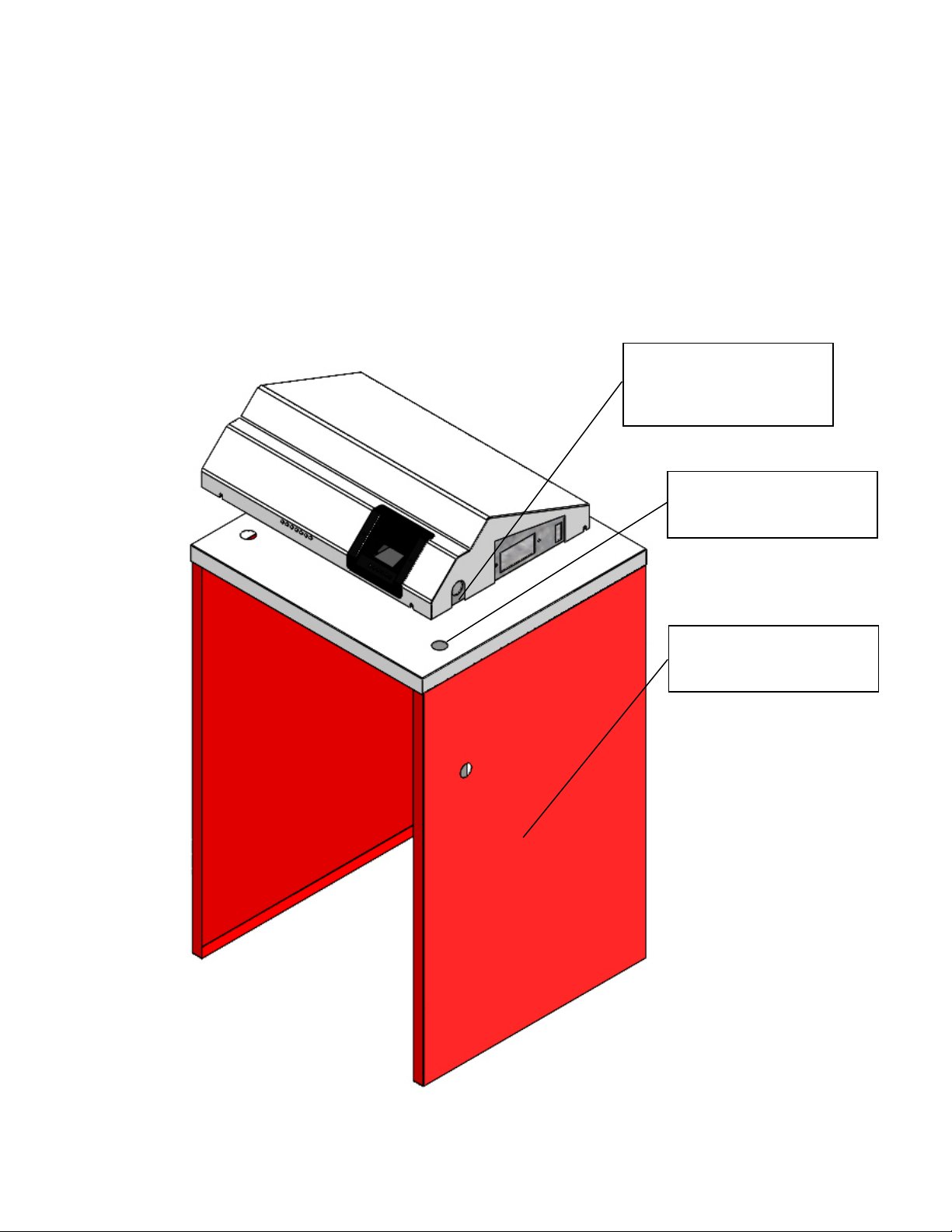
Installing The Energy Manager Pro 6000Z To a Trio Boiler
1. Lift and remove the jacket front panel.
2. Remove the two 7/8” knockouts in the jacket top panel. Note these are double tabbed
knockouts which must be removed by bending opposite the tabs.
3. Install the supplied box connectors into the 7/8” holes in the front of the Energy Manager
Pro 6000Z.
5
4. Insert the box connectors through the 7/8” hole in the jacket top panel. Thread on the
lock nuts to the box connectors and tighten.
5. Anchor the rear right-hand corner of the box to the jacket through the keyhole slot using a
self drilling screw.
6. Remove the HydroStat 3250 from the burner box and return as it is not required.
7. Remove the Hydrolevel sensor wire and ground wire which is running through the side of
the jacket, rerouting it through the box connector of the Energy Manager Pro 6000Z.
Plug the sensor wire into the HydroStat and attach the ground wire to a grounding screw.
Knockouts in Jacket
Top Panel
Box Connectors Located
on Bottom of Energy
Manager Pro 6000Z
Right Side Jacket
Panel
6
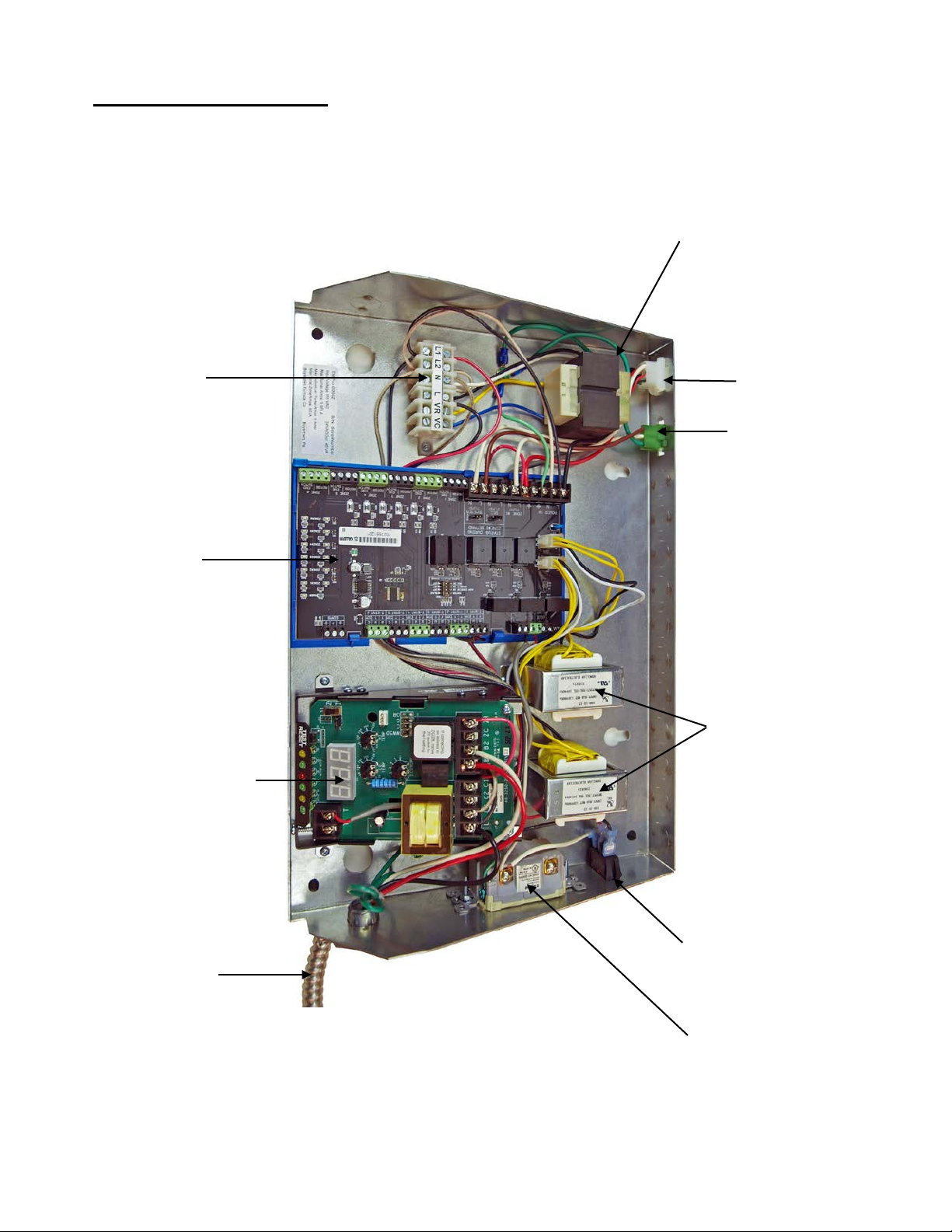
Plug’n Go Plus
Molex Plug
System Circulator
Molex Plug
Ground Fault
Outlet
Illuminated Power
Switch
Caleffi
40VA Transformers
Item No. 552200
Burner Harness
Caleffi ZVR
6 Zone Panel
Item No. 552328
Internal Components
40VA Auxiliary
Transformer
Item No. 552251
Power Input
Terminal Strip
HydroStat 3250 Plus
Item No. 508270

7
HydroStat Front Bezel Indicating Lights
1. Temp Active – HydroStat is powered and temperature function is active
2. Temp High – Illuminated when the boiler reaches the high limit temperature
3. LWCO Active – Indicates the low water cut off is active
4. Low Water – Indicates that the boiler is shut off due to a low water condition
5. Economy Active – Indicates the Thermal Targeting function is Active
6. Economy Target – Illuminates when the boiler reaches the Thermal Target.
Caleffi Zone Valve Relay
8
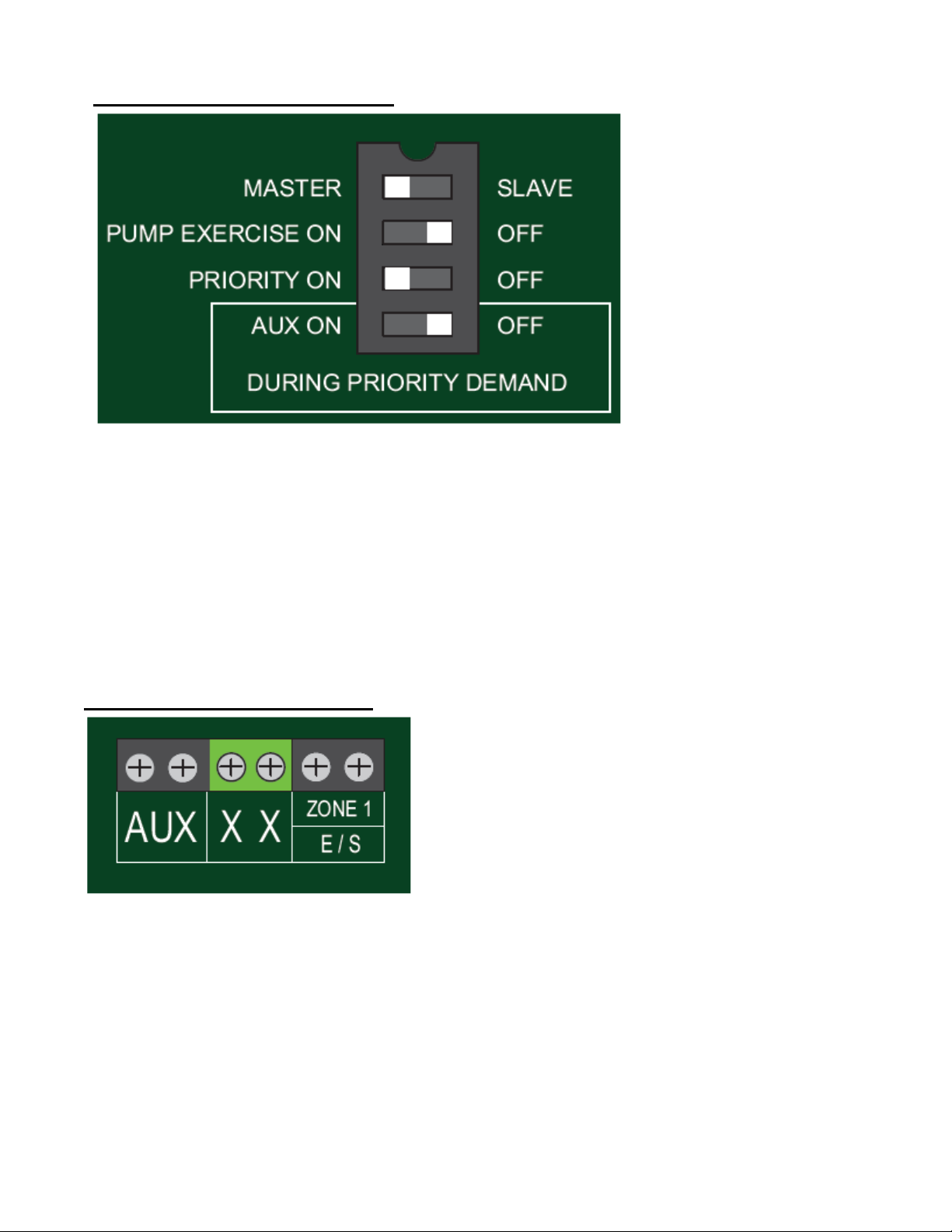
Caleffi Dip Switch Settings
The ZVR series of controls is programmed by positioning four dip switches for the following
operations.
Master / Slave: allows for unlimited expansion to additional ZVR or ZSR relays boards.
Pump Exercise ON / OFF: When exercise mode is ON, each circulator is switched on for 30 seconds
following 72 hours of inactivity.
Priority ON / OFF: When priority switch is ON, upon demand to TSTAT 1, ZONE 1 will operate as
priority and all other zones are temporarily switched off (with 1 hour time-out). When priority is OFF,
any zones that were active when ZONE 1 was switched on will remain on.
AUX ON / OFF: When AUX switch is ON, AUX dry contact is activated with a demand to any zone
including priority. When AUX is OFF, AUX dry contact is activated during any demand except priority.
Caleffi Boiler Connections
XX = Dry contact rated up to 120 VAC, 2 Amps, which is typically connected to T T on boiler control,
closes when any zone calls including priority. ZONE 1 / ES (DHW) = Dry contact, rated up to 120
VAC, 2 Amps, close with any call to ZONE 1. When priority is enabled and ZONE 1 is calling, it is
typically used to close DHW contact on boiler controls equipped with these features. AUX = Dry
contact, rated up to 120 VAC, 2 Amps, close when any zone calls and can be used as signal to a variable
speed self regulated pump. When there is a priority demand, then AUX will follow the selection of the
AUX dip switch.

9
When status jumper is placed on ON pins, the
secondary and / or system pump will continue to
operate during ZONE 1 demand. When jumper is
placed on OFF pins, the corresponding pump
will be OFF during ZONE 1 demand.
Caleffi Thermostat Connections
When a zone has a demand from a thermostat (T T / R W) the control will send 24 VAC to the
corresponding zone valve. When the zone valve end switch closes, the system and secondary pump
will switch on and the (X X) dry contact will close to signal the boiler of a heating demand. AUX dry
contact will also close as a signal to a variable speed self regulated pump or other controls. ZONE 1 can
be used for priority (either a priority pump or valve). When the priority dip switch is ON, a demand
from T-STAT 1 will activate 24VAC to VALVE 1 and the ZONE 1 pump relay, 120 VAC will switch
on after the end switch closes (requires a jumper in the end switch terminals if a valve is not used). The
DHW (ZONE 1) dry contact will also close.
Depending upon "Status During Zone 1 Demand" jumpers, the secondary and / or system pump
will either be ON or OFF.
Caleffi Status during Zone 1 Demand On / Off
Caleffi Expansion Modules
Z-oneLink™ unlimited expansion allows connecting additional ZVR & ZSR series relay controls to a
Master ZVR. Communication is accomplished by connecting three wires (thermostat wire) to the
communication terminals located in the upper right hand corner. The dip switch is positioned to Master /
Slave position. A demand for heat from any zone will fire the boiler and start the pump. Only one relay
board can be the Master and Priority, Slave is used for subsequent boards.
10
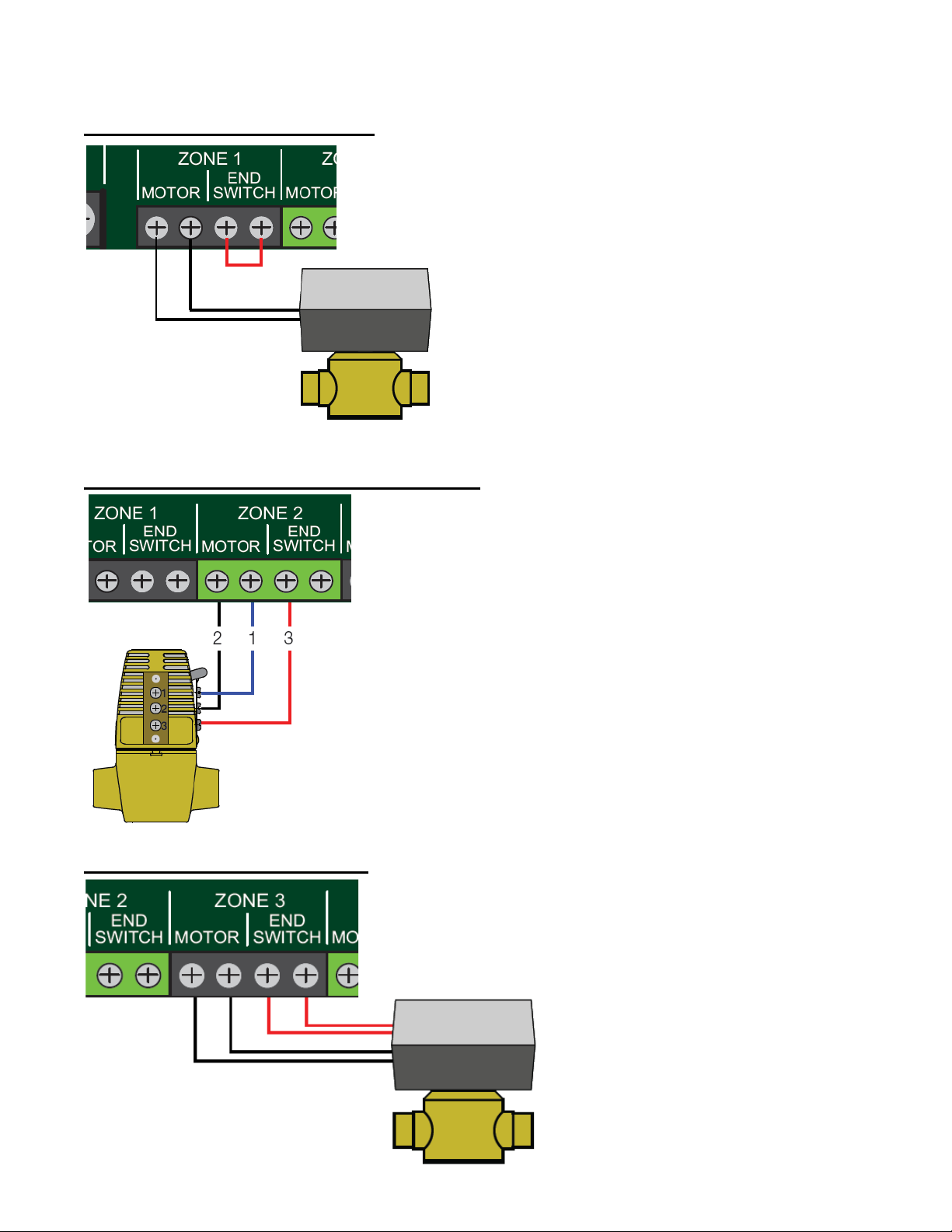
Since a two wire actuator does not
have an end switch for feedback to the
relay box, the end switch terminals
must have a jumper to simulate the
end switch. If the end switch jumper is
not installed, no demand will be sent
to the boiler and the pumps will not
turn on
The Taco 570 three wire zone valve presents a
unique wiring challenge. When connecting the
Taco 570, the wiring of this valve can only be
done in one way. The left motor terminal on
the ZVR series control must be connected to
terminal 2 on the zone valve. The right motor
terminal must be connected to terminal 1 on the
zone valve. Lastly, the left end switch terminal
must be connected to terminal 3 on the zone
valve. Failure to follow schematic will lead to
damage of product.
The four wire zone valve is the most
straight forward of the three types of
valves to wire. Simply connect the two
motor leads to motor leads, and the
two end switches to end switches.
Zone Valve Wiring 2 Wire
Zone Valve Wiring 3 Wire Taco 570
Zone Valve Wiring 4Wire

11
Danger
Electrical Wiring
Electrical Wiring Must Conform to The National Electrical Code, ANSI/NFPA and
Local Codes.
The boiler must be electrically grounded and on a separate fussed disconnect switch.
Electrical shock is hazardous. Turn off all power supplies before starting to make any wiring
connections or repairs.
Refer to wiring diagrams in this manual for electrical connections. The boiler should be connected
to a separate, electrical supply circuit with a minimum 15 amp fused rating. Use No. 14 AWG wires
rated for at least 90o C. Install a separate fused disconnect or safety switch near the boiler so all
power can be shut off for servicing.
Caution: Label all wires prior to disconnection when servicing controls. Wiring errors can cause
improper and dangerous operation. Verify proper operation after servicing.
1. The 26” long burner harness supplied is for the Riello Burner. When using with a
Beckett, burner harness length needs to be reduced to approximately 9” by removing the
90oconnector and cutting only the BX to length. Reinstall the 90oconnector. When
properly installed the burner swing door should not be able to open beyond a safe
distance without separating the Molex plug connection.
2. Wire the incoming power to the Energy Manager Pro 6000Z as indicated in the wiring
diagrams, providing overload and disconnect means as required by code.
3. Install the optional system circulator kit into the green 3-pin connector marked for the
system circulator.
4. The Plug n' Go Plus by PurePro is the most complete indirect water heater package
available. It takes installation to a new level of simplicity with all accessories factory
installed and ready to run. The tank is pre-piped and prewired with a white 6-pin
connector which plugs directly into the white 6-pin connector located in the back of the
Energy Manager Pro 6000Z marked for the Plug n' Go. Prioritization of the domestic
water is accomplished by selecting the appropriate dip switch on the ZVR106 control
module.
5. Turn on power to the Energy Manager Pro 6000Z and turn the power switch on the side
to the ‘On’ position. Check for proper voltage on input terminals “L” and “N” before
attaching output devices. FAILURE TO CHECK FOR PROPER VOLTAGE
COULD RESULT IN SYSTEM COMPONENT FAILURES.
6. Install digital non power stealing thermostats to the Caleffi ZVR106 zone board as shown
in the wiring diagrams.
7. Install the zone valves to the system zone board as shown in the wiring diagrams.
8. 24VAC 40VA auxiliary power is available on the “VR” and “VC” terminals to power
any ancillary equipment.
12
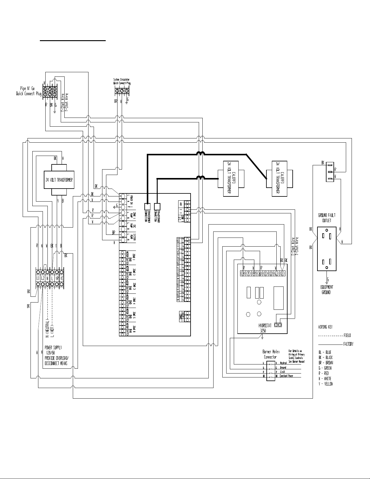
Internal Wiring

13
Field Connections – Plug’n Go Plus Indirect

14
Field Connections – Indirect Tank with Zone Valve

15
Field Connections – Indirect Tank with Circulator

16
Optional Circulator Kit
The optional circulator kit consists of either a Taco 007 or Taco 007e prewired with a green Molex
connector. This plugs directly into the green circulator plug in the rear of the Energy Manager Pro
6000Z if using it as a system circulator.
Optional Plug’n Go Plus Water Heaters
The optional Plug’n Go Plus indirect water heaters are designed to work specifically with the Energy
Manager Pro 6000Z. These prewired indirect water heaters are equipped with a 6-pin Molex
connector which plugs directly into the Energy Manager Pro 6000Z, eliminating the need for any
additional wiring.
System Checkout
1. Recheck all wiring connections.
2. Restore power to the Energy Manager Pro 6000Z and turn the Power Switch to the ‘On’
position.
3. Adjust the HydroStat high limit set point temperature to a minimum of 150oF.
Control Circuit Safety Checks
Check the safety controls on the boiler after completing the oil burner adjustments. A safety
control check for satisfactory performance must be performed.
1. High limit control - With the burner running, reduce the high limit setting until the burner shuts
off. Return the high limit to its original setting.
2. With the oil burner running, verify proper operation of the Low Water Cut Off. Refer to the
instructions provided by Hydrolevel for testing of the Low Water Cut Off. The oil burner
should shut off when the Low Water Cut Off is functioning properly.
3. To check the primary control and flame sensor, shut off oil supply with hand valve while
burner is running. Fifteen seconds after flameout the safety switch locks out, ignition stops and
the oil valve should close. To restart, open oil supply valve and reset safety switch.

17
Boiler System Installation and Service Check List
Boiler Model: _______________________ Serial No.: ____________________
Energy Manager Pro 6000Z Serial No.: _________________
Installation Date: ______________________
Installer Name: ________________________ Phone No.: ____________________
Boiler Installation
□Boiler level and in solid contact with floor?
□Boiler and burner wired per wiring diagram and National Electric Code? 120VAC wiring
Type_____ Size _____ AWG
□Burner sealed to boiler? Mounting nuts tight?
□Space is large enough to provide required clearances?
□NFPA 31 Installation of Oil Burning Equipment followed?
□Local, state and national codes, laws, regulations and ordinances followed?
Vent System
□Existing chimney and vent system inspected to NFPA 211 and in good condition?
□New vent pipe installed and properly sealed?
□Vent size checked against boiler manual and codes?
Burner Operation
□Burner Model: __________________ Nozzle: _______GPH _______Deg. ____Type_______
□Burner Pump Pressure: ______________
□Fuel filter and fuel lines installed and inspected as per burner manual?
□Air bled from oil piping? Piping checked for leaks?
□Burner started, adjusted and tested per burner manual?
Boiler Operation
□Thermostat heat anticipator set per burner manual instructions?
□Limit control tested for proper operation?
□Low Water Cut Off tested?
□Boiler observed going through several operational cycles for proper operation?
Post Installation
□Reviewed owners’ information in this manual with owner or maintenance personnel and
instructed to keep for future reference?
□Properly filled in and returned warranty registration card to Boyertown Furnace Co. Inserted
burner manual instructions with furnace manual for future us

18
Energy Manager Pro 6000Z Boiler Control
5 Year Limited Warranty
Boyertown Furnace warrants that the components factory installed and wired in the Energy Manager Pro
6000Z Boiler Control are free from defects in material and workmanship under normal usage for a period of
five (5) years from the date of original installation.
Components replaced during this warranty period which are defective in material or workmanship will carry a
warranty equal to the unexpired portion of the original component warranty or one year from the date of
replacement whichever is greater. Components in the EM Pro 6000Z Control package that are believed to
be defective must be removed from the EM Pro 6000Z casing before being shipped to Boyertown
Furnace. Boyertown Furnace at its discretion will fix or replace components.
If Boyertown Furnace determines that the returned components and/ or parts are defective and that this
warranty applies, Boyertown Furnace will furnish the replacement component to an authorized dealer who in
turn will forward the components to the heating contractor.
Boyertown Furnace is not responsible for any labor cost for removal and replacement of equipment. Please
contact your local F W Webb location for verification of warranty. This warranty does not extend to any
equipment subjected to misuse, neglect, accident or improper installation or normal wear and tear.
Upon the request of Boyertown Furnace it shall be the obligation of the purchaser to ship prepaid to
Boyertown the defective part only for inspection or repair. The alleged defective components must be
returned through the proper trade channels in accordance with Boyertown Furnace procedure in force for
handling goods returned for the purpose of inspection to determine cause of failure.
This warranty is applicable only to defect in material and workmanship of the components in the EM Pro
6000Z and shall not cover failure of the EM Pro 6000Z or any of its component parts due to any other reason
including but not limited to (1) fire, (2) floods, (3) electrical failure, (4) acts of God, (5) and negligent or
improper installation.
IMPLIED WARRANTIES OF FITNESS FOR A PARTICULAR PURPOSE AND MERCHANTABILITY SHALL BE
LIMITED TO THE DURATION OF THE EXPRESS WARRANTY SET FORTH ABOVE. WITH EXCEPTION OF ANY
WARRANTIES IMPLIED BY STATE LAW, AS HEREBY LIMITED, THE FOREGOING EXPRESS WARRANTY IS
EXCLUSIVE AND IN LIEU OF ALL OTHER WARRANTIES, GUARANTEES, AGREEMENTS AND SIMILAR
AGREEMENTS OF BOYERTOWN FURNACE WITH RESPECT TO THE REPAIR OBLIGATIONS OF BOYERTOWN
FURNACE WITH RESPECT TO THE REPAIR OR REPLACEMENT OF THE ENERGY MANAGER PLUS II.
BOYERTOWN FURNACE EXPRESSLY DISCLAIMS AND EXCLUDES ANY LIABILITY FOR CONSEQUENTIAL,
INCIDENTAL, INDIRECT, PUNITIVE OR SPECIAL DAMAGES OF ANY KIND FOR BREACH OF ANY EXPRESS OR
IMPLIED WARRANTY, INCLUDING, WITHOUT LIMITATION, INJURY OR DAMAGE TO PERSONS OR PROPERTY
OR DAMAGES FOR LOSS OF USE, INCONVENIENCE OR LOSS OF TIME, BOYERTOWN FURNACE NEITHER
ASSUMES NOR AURTHORIZES ANY OTHER PERSON TO ASSUME FOR BOYERTOWN FURNACE ANY LIABILITY
OTHER THAN THE LIMITED LIABILITY SET FORTH HEREIN.
In order to assure prompt warranty service, the owner is requested to register the product online. Product
registration may be completed online @ www.boyertownfurnace.com. If the product is not registered the
customer will be asked to provide a copy of the original invoice or other proof of purchase, original installation
date, and the serial number of the EM Pro 6000Z.
Boyertown Furnace Company
156 Holly Road
Boyertown, Pa. 19512

19

20
--------------Cut and Return This Form or Register Online at www.boyertownfurnace.com--------------------
Warranty Registration
Boyertown Furnace Co.
P.O. Box 100
Boyertown, PA 19512
Date Installed: ___________________________
Model Number: Energy Manager Pro 6000Z Serial Number: ________________________
Name of Purchaser: _________________________________________________________________________
Purchaser’s Address: ________________________________________________________________________
________________________________________________________________________
Dealer’s Name: _____________________________________________________________________________
Dealer’s Address: ___________________________________________________________________________
Table of contents
Popular Control Unit manuals by other brands

Automated Logic
Automated Logic LGE Technical instructions

NXP Semiconductors
NXP Semiconductors TWR-K64F120M user guide

Novar
Novar Trend 2VID installation instructions

Tectronix Systems
Tectronix Systems Genius operating instructions

Flow-Tek
Flow-Tek M1 Series Installation, operation and maintenance manual

Cabletron Systems
Cabletron Systems STS-LM installation guide

Silicon Laboratories
Silicon Laboratories EMBER EM358 series Reference manual

Viessmann
Viessmann VITOSOLIC 100 operating instructions

AUDAC
AUDAC APC100 MK2 user manual

Vimar
Vimar ELVOX RS12 Installation and operation manual

Moxa Technologies
Moxa Technologies NPort Z2150 Quick installation guide

Eaton
Eaton RF96APM manual


