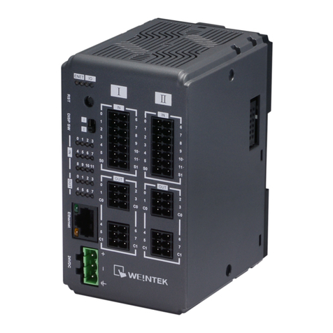
weintek iR-PU01-P User manual

User Manual
iR-PU01-P
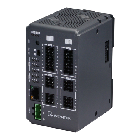
This guide walks through important information about iR-PU01-P.
V1.00

Table of Contents
1. Product Overview ...................................................................................................1
2. Specifications..........................................................................................................2
Module Specification .....................................................................................22.1
Digital Input Specification ..............................................................................22.2
Digital Output Specification ...........................................................................22.3
3. LED Indicators .........................................................................................................3
AX1 LED ..........................................................................................................33.1
Run/Error/Warn LED ......................................................................................33.2
I/O LED ...........................................................................................................33.3
4. Error Handling.........................................................................................................4
Function Block Error.......................................................................................44.1
Warning..........................................................................................................44.2
Error ...............................................................................................................54.3
5. Wiring .....................................................................................................................6
Notes on Wiring .............................................................................................65.1
Digital Input / Output Wiring .........................................................................65.2
Differential Output Wiring .............................................................................75.3
Differential Input Wiring ................................................................................85.4
6. Connecting a Coupler .............................................................................................9
iR-COP ............................................................................................................96.1
Slot and Axis...................................................................................................96.2
7. Features ................................................................................................................10
Feature List...................................................................................................107.1
High Speed Pulse Output .............................................................................107.2
High Speed Pulse Input (Encoder) ...............................................................127.3
Positioning Control (Buffer Mode Supported).............................................137.4
Velocity Control............................................................................................147.5
Homing.........................................................................................................157.6
Synchronized Motion (Gear / MPG).............................................................157.7
Digital Cam Switch .......................................................................................157.8
Capture.........................................................................................................167.9
Configurable I/O...........................................................................................167.10
Motion Control working with I/O Control....................................................167.11
8. Object Dictionary..................................................................................................17
Manufacturer Specific Profile Area (5500h - 58FFh) ...................................178.1
8.1.1 Digital Input:5500h ...........................................................................20
8.1.2 Pulse Input Method:5501h ...............................................................21

8.1.3 Input Polarity:5502h .........................................................................22
8.1.4 Digital Input Function:5503h ............................................................22
8.1.5 Digital Input Filter:5504h ..................................................................22
8.1.6 Digital Output:5510h ........................................................................23
8.1.7 Pulse Output Method:5511h ............................................................23
8.1.8 Output Polarity:5512h ......................................................................24
8.1.9 Digital Output Function:5513h .........................................................24
8.1.10 Digital Output Abort Connection Option:5514h...............................24
8.1.11 PWM Output Setting:551Ah .............................................................25
8.1.12 Axis Setting0:5520h...........................................................................26
8.1.13 Axis Setting1:5521h...........................................................................26
8.1.14 Additional position modulo range:5528h .........................................26
8.1.15 Additional home offset:5529h ..........................................................26
8.1.16 Gear Motion Setting:5530h ..............................................................26
8.1.17 DigitalCamSwitch Enable:5580h .......................................................26
8.1.18 DigitalCamSwitch Track Position ValueSource:5581h.......................27
8.1.19 DigitalCamSwitch MC_CAMSWITCH_REF:5583h..............................27
8.1.20 Motion Output Setting:558Fh...........................................................27
8.1.21 Capture Enable:5590h.......................................................................28
8.1.22 Capture Status:5591h .......................................................................28
8.1.23 Capture Setting:5592h ......................................................................28
8.1.24 Capture Status:5598h .......................................................................29
8.1.25 Motion Trigger Setting:559Fh ...........................................................29
Standardized device profile Area (6000h - 7FFFh).......................................308.2
9. Motion Control Function Blocks ...........................................................................32
Motion Control Function Block List..............................................................329.1
Download and Install ...................................................................................329.2
MC_Status....................................................................................................339.3
Execution of Function Blocks .......................................................................349.4
MC_Power....................................................................................................359.5
MC_MoveVelocity........................................................................................369.6
MC_Home ....................................................................................................369.7
MC_MoveAbsolute ......................................................................................379.8
MC_MoveRelative........................................................................................379.9
MC_STOP and MC_Halt ...............................................................................389.10
MC_Reset .....................................................................................................399.11
MC_Gear ......................................................................................................409.12
10. Quick Start of iR-PU01-P in CODESYS CANopen ...................................................41

Install and Add Weintek Library ...................................................................4110.1
Launch New Project and Add iR-PU01-P......................................................4110.2
Configuring Motion Control Parameters......................................................4210.3
Declaration and Programming .....................................................................4210.4
Axis I/O Mapping..........................................................................................4310.5
Login and Run Trial Operation .....................................................................4410.6

iR-PU01-P
1
1. Product Overview
a
Terminal
b.c
Expansion Connector
英文版 簡中版 日文版
81mm [3.19"]
109mm [4.29"]
27mm [1.06"]
Top View
Side ViewSide View
Bottom View
a
b
c
81mm [3.19"]
109mm [4.29"]
b
c
81mm [3.19"]
109mm [4.29"]
b
c
27mm [1.06"]
Front View
a
iR-DQ08-RiR-DXXX
iR-PXXX
27mm [1.06"]
a
27mm [1.06"]
a
iR-DQ08-RiR-DXXX
iR-PXXX
27mm [1.06"]
a
27mm [1.06"]
a
iR-DQ08-RiR-DXXX
iR-PXXX

iR-PU01-P
2
2. Specifications
Module Specification2.1
Module Name
iR-PU01-P
Number of Axis
1- Axis
Specification
PCB Coating
Yes
Enclosure
Plastic
Dimensions WxHxD
27 x 109 x 81 mm
Weight
Approx. 0.12 kg
Mount
35mm DIN rail mounting
Environment
Protection Structure
IP20
Storage Temperature
-20°~ 70°C (-4°~ 158°F)
Operating
Temperature
0°~ 55°C (32°~ 131°F)
Relative Humidity
10% ~ 90% (non-condensing)
Connection
Cross-section
AWG 28-16
Certification
EMC Immunity
Conforms to
EN 55032: 2012+AC: 2013, Class A
EN 61000-6-4: 2007+A1:2011
EN 55024: 2010+A1: 2015
EN 61000-6-2:2005
Digital Input Specification2.2
Item
Sink Input
Differential Input
Number of Inputs
4
3 (A/B/Z phase )
Input current
24 VDC, 5 mA
Meets the Requirements of ANSI
Standards TIA/EIA-485-A
HIGH Level Input Voltage
15~28 VDC
-
LOW Level Input Voltage
0~5 VDC
-
Maximum input frequency
200KHz
2MHz
Input Impedance
3 KΩ
-
Indicators
Red LED Input State
Digital Output Specification2.3
Item
Source Output
Differential Output
Number of Outputs
4
2(A/B phase )
Output Voltage
24VDC , 50 mA
Meets the Requirements of ANSI
Standards TIA/EIA-485-A
Maximum Output frequency
40KHz
2MHz
Indicators
Red LED Input State

iR-PU01-P
3
3. LED Indicators
AX1 LED3.1
Run/Error/Warn LED3.2
Run LED
Description
OFF
Axis is not ready
Blinking
Axis is ready
ON
Axis is busy
Error LED
Description
OFF
No errors
ON
Error occurred
Warn LED
Description
OFF
No warnings
ON
Warning: Unable to reach the specified
velocity trajectory.
I/O LED3.3
IN 0-3 State
Description
OFF
Digital Input OFF
ON
Digital Input ON
OUT 0-3 State
Description
OFF
Digital Output Set OFF
ON
Digital Output set ON
PA/PB State
Description
OFF
PA/PB Pulse Output OFF
ON
PA/PB Pulse Output ON
A/B/Z State
Description
OFF
A/B/Z Pulse Input OFF
ON
A/B/Z Pulse Input ON
AX1
AX1 Run LED
AX1 Error LED
AX1 Warm LED

iR-PU01-P
4
4. Error Handling
Function Block Error4.1
When using a function block and an error occurs, the diagnostic value is output to
the pin in the function block, and ErrorID contains the error code. The following is a
list showing how to handle errors.
State
Description
Error Handling
AXIS_NOT_READY
The axis is not ready for
operation.
After resolving other errors, enable
MC_Power, wait until the Status
turns to True, and then restart.
AXIS_BUFFER_FULL
Positioning Buffer is full.
Please modify the program to avoid
buffering too many positioning
controls, and use MC_Reset to clear
the error.
AXIS_MOTION_ERROR
A motion error occurs.
Please see chapter 4.3 in this
manual.
AXIS_HOMING_ERROR
A homing error occurs.
Please check the homing related
settings and see Chapter 4.3 in this
manual.
AXIS_TRANSITION_ERROR
Incorrect transition of motion
mode.
Please modify the program to avoid
associating Homing with other
motions, and avoid associating
Positioning Buffer with
non-positioning motions. Please
clear the error using MC_Reset.
Warning4.2
Warnings occur when:
Warn LED is on
Bit 7 in Digital Input Byte0 is 1
Digital Input Byte0
Axis Number
Index
Sub-index
Axis 0
5500h
01h
Axis 1
5600h
01h
Axis 2
5700h
01h
Axis 3
5800h
01h
In positioning control, a warning occurs when:
The specified acceleration/deceleration rate cannot be reached before reaching
the target velocity due to jerk limitation.
In the distance for positioning, acceleration/deceleration takes a long time so
that target velocity cannot be reached.

iR-PU01-P
5
When warning, PU will specify a lower target velocity, and remove jerk limitation and
finish positioning. To keep the jerk limitation, user may adjust target velocity,
acceleration/deceleration rate to avoid warning.
Error4.3
Errors are indicated in the following ways:
Error LED is on
ErrorID of Function Block is AXIS_MOTION_ERROR
The status of the axis is ErroStop
When an error occurs, find the error code and troubleshoot the error. Use MC_Reset
to clear the error, and then use MC_Power to make the axis return to Standstill state.
Error Code
Description
Cause of Error
16#6180
Motion Error 0
MC_POWER is OFF during motion. (Disconnected, or PLC
Stop/Reset).
16#6181
Motion Error 1
Changes to an incorrect mode (CiA402) during motion.
16#6182
Motion Error 2
iR-PU01-P calculates trajectory incorrectly. (Including
errors caused by Blending.)
16#618A
Homing Error
Incorrect Homing mode or an external signal that is not
configured is used.
16#6280
Software Limitation
The position is going to exceed or already exceeds the
software limitation.
16#6281
Prohibited Direction
Movement in prohibited direction.
16#8612
Exceeding Position Range
Target position exceeds software limitation or axis range.
16#6320
Function Block Error
Invalid parameters used.
16#6380
Parameter Error 0
Incorrect pulse output mode used.
16#6381
Parameter Error 1
Incorrect pulse output mode used.
16#6382
Parameter Error 2
The product of the numerator and denominator of the
ratio is too large. (INT_MAX)
16#6383
Parameter Error 3
The product of the numerator and denominator of the
ratio of the 1st axis is too large.
16#6384
Parameter Error 4
The product of the numerator and denominator of the
ratio of the 2nd axis is too large.
16#9080
External Signal Error 0
Positive limit signal is triggered.
16#9081
External Signal Error 1
Negative limit signal is triggered.
16#9082
External Signal Error 2
Immediate stop signal is triggered.
16#7500
Communication Error
Disconnection or Heartbeat Timeout has occurred.

iR-PU01-P
6
5. Wiring
Notes on Wiring5.1
Wiring for Differential Communication
a. Wire length should be minimized (Max: 500m shielded, 300m unshielded).
b. Please use twisted pair cables conform to the impedance matching.
c. If wiring is to be exposed to lightning or surges, use appropriate surge
suppression devices.
d. Keep AC wiring separated from signal wires.
e. Keep high energy and rapidly switching DC power wiring separated from
signal wires.
Wiring for Digital Output
Digital output voltage range: 24VDC (-15%/+20%)
The maximum output voltage per point is 50mA, please take this into consideration
when wiring.
Wiring for Digital Input
Digital input voltage range: 15~28VDC (ON), 5V (OFF)
Input impedance: 3 KΩ
Please take this into consideration when wiring.
Digital Input / Output Wiring5.2

iR-PU01-P
7
Differential Output Wiring5.3
GN
D
Source Digital Input
Source Digital
Output
+24VDC

iR-PU01-P
8
Differential Input Wiring5.4

iR-PU01-P
9
6. Connecting a Coupler
iR-COP6.1
An iR-COP coupler supports up to 4 iR-PU01-P modules at a time.
iR-COP software version should be 1.00.3 or later.
EDS file version should be Revision 16#00000003
Slot and Axis6.2
An iR-COP coupler supports up to 4 iR-PU01-P modules at a time. The 4 iR-PU01-P
modules use iR-COP’s axes respectively, which are Axis 0~3. The iR-PU01-P module
nearest to iR-COP uses Axis 0, and the second uses Axes 1, and so on.
As shown in the following figure, two iR-PU01-P modules are installed respectively on
Slot 2 and Slot 4. The iR-PU01-P module installed on Slot 2 uses the first axis (Axis 0),
while the iR-PU01-P installed on Slow 4 uses the second axis (Axis 1).
Axis0
Axis1
Slot1
Slot2
Slot3
Slot4
DI16-K
PU01-P
PU01-P
DI16-K

iR-PU01-P
10
7. Features
Feature List7.1
No.
Feature
1
High Speed Pulse Output
2
High Speed Pulse Input (encoder)
3
Positioning Control (Buffer Mode supported).
4
Velocity Control allows speed specification.
5
Homing, supports over 30 modes.
6
Synchronized Motion (Gear/MPG)
7
Digital Cam Switch
8
Capture
9
Configurable I/O
High Speed Pulse Output7.2
iR-PU01-P can output 2MHz pulses to control the connected servo/step motor
(velocity and positioning control). Output modes include CW/CCW, Pulse/Direction,
Pulse Only, A/B phase * 1、A/B phase * 2、A/B phase * 4. The output mode is
configured using Object Dictionary-Index 0x5511 (Axis 0).
Output Modes
Schematic
CW/CCW

iR-PU01-P
11
Pulse/Direction
Pulse only
A/B Phase

iR-PU01-P
12
High Speed Pulse Input (Encoder)7.3
iR-PU01-P can receive up to 2MHz pulse input from the signal output by an encoder
or Manual Pulse Generator (MPG). Input modes include CW/CCW, Pulse/Direction,
Pulse Only, A/B phase * 1、A/B phase * 2、A/B phase * 4. The input mode is
configured using Object Dictionary-Index 0x5501 (Axis 0).
Input Modes
Schematic
CW/CCW
Pulse/Direction
Pulse only

iR-PU01-P
13
A/B Phase
Positioning Control (Buffer Mode Supported)7.4
Weintek provides a library of motion control function blocks, and the function blocks
relating to positioning control include: MC_MoveAbsolute and MC_MoveRelative,
which can perform absolute/relative positioning for the specified target position or
for the specified travel distance from current position. Buffer Mode can be used
when executing more than one motion instruction.

iR-PU01-P
14
Velocity Control7.5
Weintek provides MC_MoveVelocity function block for controlling the speed of the
motor. The module allows V-bias initial speed specification, which makes the motor
rotate at specified velocity immediately regardless of acceleration/deceleration rate
Buffered
P0
P1
P2
V1
V2
P0
P1
P2
V
1
V
2
Buffered
P0
P1
P2
V
1
V2
BlendingPrevious
P0
P1
P2
V1
V2
BlendingPrevious

iR-PU01-P
15
when receiving a velocity command for a velocity slower than the initial speed. This
can reduce resonance at low speeds. The following diagram shows how velocity
changes when V-bias is used.
Homing7.6
The module provides 37 homing modes designed according to CiA402. The homing
modes include: proximity sensors, index, positive and negative limits.
Synchronized Motion (Gear / MPG)7.7
Synchronized motion control is achieved by specifying the ratio between the master
axis (Pulse Input) and the slave axis (Pulse Output). Manual Pulse Generator (MPG) is
one of the applications.
Digital Cam Switch7.8
This feature simulates mechanical cam switch using digital method, which allows
settings that can by realized easier in this manner. Each track corresponds to one
iR-PU01-P output point. Users can add multiple switches (16 in maximum) to a track,
with each switch specifies different position and direction, in order to plan the
distance and time output by a point. The position source can be a commanded
position (1st axis) or an actual position (2nd axis), and ratio can be configured
respectively for each axis.

iR-PU01-P
16
Capture7.9
Each iR-PU01-P has five Capture channels for capturing the current axis position
value or the timer value of iR-PU01-P, on the rising or falling edge of the input signal.
The change of position or time interval can be observed by comparing two captured
values (two values captured by one channel, or compared to the latest value from
other channels).
Continuous capture is also possible, to do so, the interval of the external signals
should be greater than 1ms. Please take the execution cycle and communication
cycle into consideration in order to read the capture value before the next capture
takes place.
Configurable I/O7.10
Each I/O of the module, including pulse input/output, has its unique function
designed for motion control, but using them as general digital I/O points is possible.
Motion Control working with I/O Control7.11
Apart from homing, motion control can be triggered by using an external input signal.
After positioning is completed, IO_Ctrl Function Block and Object Dictionary can be
used to assign multiple output points to output values at a time.
Table of contents
Other weintek Control Unit manuals
Popular Control Unit manuals by other brands

Phoenix Mecano
Phoenix Mecano Dewert Okin SG 300 installation instructions

Efka
Efka DC 1550 manual

Sony
Sony HXCU-100 Service manual

Caltta
Caltta ZXIMCU PT01 P200 Operation manual

S+S Regeltechnik
S+S Regeltechnik Rymaskon 600 operating instructions

Comunello
Comunello CU 230V HP Installation and user manual