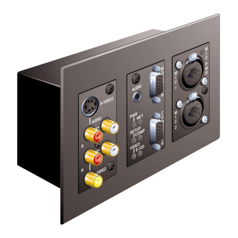
B+B SmartWorx Airborne M2M ABDN-er-DP55 Series User manual

Airborne M2M™
USER MANUAL
ABDN-er/se-DP55x series
ABDN-er/se-IN5xxx series
_Revision 1.3
_September 2018

AirborneM2M™ User Guide
2
Advantech B+B SmartWorx - Americas
707 Dayton Road
Ottawa, IL 61350 USA
Phone (815) 433-5100
Fax (815) 433-5105
Advantech B+B SmartWorx - European Headquarters
Westlink Commercial Park
Oranmore, Co. Galway, Ireland
Phone +353 91-792444
Fax +353 91-792445
www.advantech-bb.com
support@advantech-bb.com
Documentation Number: ABDx-xx_ProductSeries_r3_3818um

AirborneM2M™ User Guide
3
TABLES OF CONTENTS
Tables of Contents ...........................................................................................................................................3
Conventions ......................................................................................................................................................7
Terminology ......................................................................................................................................................7
Notes ..............................................................................................................................................................7
Caution ..............................................................................................................................................................7
File Format........................................................................................................................................................7
Product Description..........................................................................................................................................8
Features.............................................................................................................................................................9
Device Types ..................................................................................................................................................10
Serial ............................................................................................................................................................10
Ethernet ...........................................................................................................................................................10
Serial + Ethernet ............................................................................................................................................10
Enterprise Class .............................................................................................................................................10
Industrial Class...............................................................................................................................................11
Block Diagrams...............................................................................................................................................12
Pin Out and Connectors ................................................................................................................................13
Serial Ports .....................................................................................................................................................13
Ethernet Port...................................................................................................................................................15
Connector Definition ......................................................................................................................................16
OEM Reset Switch (Factory Reset) ............................................................................................................16
Enterprise Serial Interface Jumpers............................................................................................................17
Indicator LEDs ................................................................................................................................................17
Electrical & RF Specification.........................................................................................................................19
AC Electrical Characteristics – Transmitter ...............................................................................................21
Performance/Range ......................................................................................................................................21
Antenna............................................................................................................................................................22
Antenna Selection..........................................................................................................................................22
Host Board Mounted Antenna......................................................................................................................22
Host Chassis Mounted Antenna ..................................................................................................................23
Embedded Antenna .......................................................................................................................................23
Antenna Location ...........................................................................................................................................24
Performance ...................................................................................................................................................24
Mechanical Outline – Enterprise Class .......................................................................................................26
Mechanical Outline – Industrial Class .........................................................................................................27
Getting Started................................................................................................................................................28
Unpack the AirborneM2M™ Device............................................................................................................28
Connect AirborneM2M™ to host .................................................................................................................28
Attach Antenna and Power-up the AirborneM2M™..................................................................................28
Configuring Device – Industrial Serial (ABDx-SE-IN5xxx) .......................................................................28
Configuring Device – Enterprise/Industrial Ethernet (ABDx-ER-DP5xx/IN5xxx) ..................................32
Using the Web Interface................................................................................................................................36
Navigation Bar ................................................................................................................................................37
Feature Links..................................................................................................................................................38
Navigating the Website .................................................................................................................................38
Updating a Field .............................................................................................................................................39
Uploading Certificates ...................................................................................................................................39
Upload Configuration Files ...........................................................................................................................40

AirborneM2M™ User Guide
4
Updating Firmware ........................................................................................................................................41
Express Setup Configuration Page .............................................................................................................44
Configuring the Wireless Interface...............................................................................................................47
Configuring for Infrastructure Networks......................................................................................................47
Configuring for AdHoc Networks .................................................................................................................48
Configuring the Security Settings.................................................................................................................49
Configuring for WEP Security ......................................................................................................................49
Configuring for WPA-PSK Security .............................................................................................................50
Configuring for WPA2-PSK Security ...........................................................................................................51
Configuring for PEAP Security.....................................................................................................................52
Configuring Network Settings .......................................................................................................................53
Configuring DHCP on WLAN Interface.......................................................................................................53
Configuring DHCP on Ethernet Interface ...................................................................................................54
Configuring a Static IP Address on WLAN Interface ................................................................................55
Configuring a Static IP Address on Ethernet Interface.............................................................................56
Configuring Serial Device Server.................................................................................................................57
Configuring Serial Port for Access on Telnet Port ....................................................................................57
Configuring Serial Port 1 for Access on Tunnel Port ................................................................................59
Configuring Serial Port 2 for Access on Tunnel Port ................................................................................60
Configuring Serial Port 1 as TCP Client .....................................................................................................61
Configuring Serial Port 2 as TCP Client .....................................................................................................62
Installing and Using the Airborne VirtualCOM Driver................................................................................63
Replacing a Serial Cable...............................................................................................................................66
Configuring Ethernet Adapter .......................................................................................................................68
Router Functionality.......................................................................................................................................68
Public Network Interface ...............................................................................................................69
Private Network Interface..............................................................................................................70
Bridge Functionality .......................................................................................................................................72
MAC Cloning...................................................................................................................................................73
Web Page Overview......................................................................................................................................74
Module Status ...............................................................................................................................75
Ethernet Status..............................................................................................................................76
Ethernet DHCP Clients .................................................................................................................77
Radio Statistics..............................................................................................................................78
Ethernet Statistics .........................................................................................................................79
Express Setup ...............................................................................................................................80
WLAN Settings ..............................................................................................................................81
WLAN Security Settings................................................................................................................82
Network Settings ...........................................................................................................................84
Serial Port Settings .......................................................................................................................86
Serial Port 2 Settings ....................................................................................................................87
Connection Settings ......................................................................................................................88
Ethernet Settings...........................................................................................................................90
Wireless Routing Settings .............................................................................................................91
Ethernet Routing Settings .............................................................................................................92
Advanced Settings ........................................................................................................................93
Upload Configuration File..............................................................................................................96
List Configuration File ...................................................................................................................97
Delete Configuration File...............................................................................................................98
Active Configuration ......................................................................................................................99
User Configuration ......................................................................................................................100
OEM Configuration......................................................................................................................101

AirborneM2M™ User Guide
5
Factory Configuration..................................................................................................................102
WPA Configuration......................................................................................................................103
List Certificates............................................................................................................................104
Upload Certificate........................................................................................................................105
Delete Certificate.........................................................................................................................106
Network (Home Page).................................................................................................................107
Discover Airborne Modules .........................................................................................................108
Scan for Access Points ...............................................................................................................109
Maintenance (Home Page) .........................................................................................................110
Update Module Firmware............................................................................................................111
Reset Factory Defaults................................................................................................................112
Restart Module ............................................................................................................................113
Set System Time .........................................................................................................................114
Blink the POST LED....................................................................................................................115
Stop Blinking the POST LED ......................................................................................................116
Certification & Regulatory Approvals.........................................................................................................117
FCC Statement.............................................................................................................................................117
FCC RF Exposure Statement ....................................................................................................................117
Information for Canadian Users (IC Notice).............................................................................................118
FCC/IC Modular Approval...........................................................................................................................119
Regulatory Test Mode Support ..................................................................................................................119
Physical & Environmental Approvals.........................................................................................................120
Figures
Figure 1 - Enterprise AirborneM2M™ Device................................................................................................10
Figure 2 - Industrial AirborneM2M™ Device..................................................................................................11
Figure 3 - ABDx-ER-DP5xx Block Diagram ...................................................................................................12
Figure 4 - ABDx-ER/SE-IN5xxx Block Diagram ............................................................................................13
Figure 5 - DE-9 (DB-9) Connector Pin-out .....................................................................................................13
Figure 6 - Ethernet Jack Pin Out .....................................................................................................................15
Figure 7- Interface Selection Jumpers............................................................................................................17
Figure 8 - Website Login...................................................................................................................................36
Figure 9 - Default Home Page .........................................................................................................................37
Figure 10 - Website Navigation Bar ................................................................................................................37
Figure 11- Feature Links...................................................................................................................................38
Figure 12 - Airborne Web Page .......................................................................................................................38
Figure 13 - Upload Certificate Web page .......................................................................................................39
Figure 14 - Upload Configuration Web Page.................................................................................................40
Figure 15 - Firmware Update Page.................................................................................................................42
Figure 16 - Firmware Update in Progress ......................................................................................................42
Figure 17 - Firmware Update Complete .........................................................................................................43
Figure 18 - Express Setup Page .....................................................................................................................44
Figure 19 - Ethernet Bridge Functionality.......................................................................................................68
Figure 20 - Airborne Ethernet Bridge IP Configuration ................................................................................69

AirborneM2M™ User Guide
6
Tables
Table 1 – Serial Port Pin Definition ......................................................................................................... 14
Table 2 - Serial Ports by Product Class.................................................................................................. 14
Table 3 - Ethernet Connector Pin Out .................................................................................................... 15
Table 4 - Connector Description.............................................................................................................. 16
Table 5 - OEM Reset Procedure ............................................................................................................. 16
Table 6 - Enterprise LED Indicators ........................................................................................................ 17
Table 7 - Industrial LED Indicators .......................................................................................................... 18
Table 8- Absolute Maximum Values1...................................................................................................... 19
Table 9 - RF Characteristics – 802.11a/b/g/n........................................................................................ 19
Table 10 - Supported Data Rates by Band ............................................................................................ 19
Table 11 - Operating Channels................................................................................................................ 20
Table 12 - Radio Typical Performance Range ...................................................................................... 21
Table 13 - Embedded Antenna Options ................................................................................................. 23
Table 14 - SE-IN5xxx Accessing the Web Interface............................................................................. 28
Table 15 – ER-DP5xx/IN5xxx Accessing the Web Interface............................................................... 32
Table 16 - Navigation Bar Items .............................................................................................................. 37
Table 17 - Uploading Certificates ............................................................................................................ 40
Table 18 - Uploading Configurations ...................................................................................................... 41
Table 19 - Updating Firmware ................................................................................................................. 43
Table 20 - Express Page Setup............................................................................................................... 45
Table 21 - Configuring Wireless Interface - Infrastructure................................................................... 47
Table 22 - Configuring Wireless Interface - AdHoc .............................................................................. 48
Table 23 - Configuring for WEP Security ............................................................................................... 49
Table 24 - Configuring for WPA Security ............................................................................................... 50
Table 25 - Configuring for WPA2 Security ............................................................................................. 51
Table 26 - Configuring for PEAP Security.............................................................................................. 52
Table 27 - Configuring DHCP - WLAN ................................................................................................... 53
Table 28 - Configuring DHCP - Ethernet................................................................................................ 54
Table 29 - Configuring Static IP - WLAN................................................................................................ 55
Table 30 - Configuring Static IP - Ethernet ............................................................................................ 56
Table 31 – Configure Data Tunnel on Telnet Port ................................................................................ 57
Table 32 - Data Tunnel using Telnet Port .............................................................................................. 58
Table 33 – Configure Data Tunnel on Serial Port 1 Tunnel Port (TCP) ............................................ 59
Table 34 - Data Tunnel using Tunnel Port on Serial Port 1................................................................. 59
Table 35 – Configure Data Tunnel on Serial Port 2 Tunnel Port (TCP) ............................................ 60
Table 36 - Data Tunnel using Tunnel Port on Serial Port 2................................................................. 60
Table 37 - Configure Serial Port 1 as TCP Client ................................................................................. 61
Table 38 - Configure Serial Port 2 as TCP Client ................................................................................. 62
Table 39 - Install VCOM............................................................................................................................ 63
Table 40 - Cable Replacement - Slave Configuration .......................................................................... 66
Table 41 - Cable Replacement - Master Configuration........................................................................ 67
Table 42 - Ethernet Adapter interface Configuration - DHCP ............................................................. 70
Table 43 - Ethernet Adapter interface Configuration - Static IP.......................................................... 71
Table 44 - Ethernet Adapter interface Configuration ............................................................................ 72
Table 45 - Regulatory Approvals ........................................................................................................... 117
Table 46 - Modular Approval Grant Numbers...................................................................................... 119
Table 47 - Mechanical Approvals .......................................................................................................... 120

AirborneM2M™ User Guide
7
CONVENTIONS
The following section outlines the conventions used within the document. Where convention is deviated
from, the deviation takes precedence and should be followed. If you have any questions related to the
conventions used or clarification of indicated deviation, please contact B+B SmartWorx Sales or
Wireless Support.
TERMINOLOGY
Airborne Device Server and AirborneM2M Device Server terms are used to describe the devices in the
opening section of this document. After this section, the term module will be used to describe the devices.
NOTES
A note contains information that requires special attention. The below convention will be used. The area
next to the indicator will identify the specific information and make any references necessary.
The area next to the indicator will identify the specific information and make any
references necessary.
CAUTION
A caution contains information that, if not followed, may cause damage to the product or injury to the user.
The shaded area next to the indicator will identify the specific information and make any references
necessary.
The area next to the indicator will identify the specific information and make any
references necessary.
FILE FORMAT
These documents are provided as Portable Document Format (PDF) files. To read them, you need Adobe
Acrobat Reader 4.0.5 or higher. For the latest version of Adobe Acrobat Reader, go to the Adobe website
(www.adobe.com).

AirborneM2M™ User Guide
8
PRODUCT DESCRIPTION
This guide describes the AirborneM2M™ device servers and wireless adapters from B+B SmartWorx,
Inc. AirborneM2M™ is a fully integrated, 802.11 wireless Local Area Network (LAN) connectivity device
designed to provide wireless LAN and Internet connectivity in industrial, scientific, medical and
transportation applications where an existing communications interface already exists. The
AirborneM2M family of products supports Serial (RS-232/422/485), Ethernet and a combination these
interfaces in a range of packaging options.
The AirborneM2M™ product family provides true plug-and-play wireless connectivity. By delivering
convenient, easy-to-deploy wireless network connectivity, the device servers and adapters significantly
reduce the complexities of wireless system deployment and network implementation. At the same time,
users can move equipment without the cost and time associated with wired network drops and
environment restrictions. This provides flexibility for seasonal demands, line and staffing changes, and
more.
The AirborneM2M™ family includes models with dual band radios; the ABDNx supports 802.11a/b/g/n.
The AirborneM2M™ Serial Bridges and Device Servers provide a simple connection between the
802.11 wireless LAN and three leading serial interfaces: RS-232, RS-422, and RS-485.
The Bridge acts transparently between any device using these interfaces and a wireless LAN. Using the
B+B SmartWorx virtual communications port Windows device driver, OEMs can communicate with their
devices from any workstation on the same network as if the workstation and devices were directly
attached through a serial port.
The AirborneM2M™ Ethernet Adapter provides a link between the 802.11 wireless LAN and any
Ethernet-ready device with an RJ-45 connector. It acts transparently between the device and a wireless
LAN. By integrating AirborneM2M™ into existing and legacy platforms, OEMs can significantly enhance
their products by delivering increased value and functionality to their entire customer base.
The Airborne family includes the ability to simultaneously use the serial-to-wireless and Ethernet-to-
wireless connectivity in the same unit. This capability provides for multiple connections to the same
machine or consolidation of multiple wireless units into a single device.
The AirborneM2M™ products open the world of remote device monitoring and management, as well as
wide-area data collection, to any device or machine or plant that has an external serial or Ethernet
connection and a network infrastructure. A development kit provides quick and easy access to the
bridge’s configuration and functions, while providing OEMs with a platform to develop their branded
solutions. The bridge also provides the capability to perform firmware upgrades that allow new features
to be added quickly and easily, protecting your investment.
The Enterprise family includes the most advanced security support available for the device class in the
industry, including WPA, WPA2 and full Enterprise support. The devices can be used with the most
advanced WLAN networks being deployed today. Airborne products are based on the industry leading
Airborne device server and wireless adapter technology from B+B SmartWorx, providing a fully
compatible and familiar device interface across all product ranges. If you have used one of them, you
have used them all.

AirborneM2M™ User Guide
9
FEATURES
802.11 WiFi Radio with 32-bit ARM9 CPU (128Mb SDRAM, 64Mb Flash)
−ABDN series supports 802.11a/b/g/n
Integrated Airborne Device Server and Wireless Adapter Technology.
Supports WEP, WPA, WPA2 and 802.1x Supplicant, with Certificates.
The wireless device server includes integrated:
−802.11 Radio Driver
−TCP/IP stack, UDP, telnet, FTP server
−Data bridging and buffering
−Command Line Interface (CLI)
−Web Interface
−WPA Supplicant
−DHCP Server (Ethernet Interface)
−Firewall and Port Forwarding (Ethernet)
−FTP Server
Supports flexible antenna selection.
Operating Temperature (-40 to +85 °C)
Storage Temperature (-40 to +85 °C)
Industry standard wired connections:
−DB-9 Serial Connectors (RS-232/422/485)
−RJ-45 (10/100 Ethernet)
Multiple host interfaces supported:
−Single and Dual Serial (RS-232/422/485) – up to 921K baud
−10/100 Ethernet
Uses 5-36 VDC power source input
Power connector options include 2.1mm Barrel Jack, Terminal Block and custom
connectors.
Power-over-Ethernet (PoE) using an 802.3af Class 1 PSE device (ABDx-ER-IN5xx8
models)
Integrated Site Survey mode
Advanced Low Power modes
Rugged Mounting options
Virtual COM Port driver (Win XP, Vista, 7)
Worldwide Regulatory Support (FCC, IC, CE)

AirborneM2M™ User Guide
10
DEVICE TYPES
This manual covers all variations available in the AirborneM2M™ device family. The following section
identifies the different types both functional and classification. In most cases, the functional types are
available in the listed classifications. If you are not certain which type you have or would like clarify the
available options, please contact B+B SmartWorx Sales or Technical Support.
SERIAL
This device supports a single or dual serial port and provides serial to 802.11 bridging. The serial devices
can support one or more of the following serial interface types:
RS-232
RS-422
RS-485
Default configuration on all models is RS-232. Conversion to RS-422/RS-485 requires software
configuration and, in some models, jumper setting changes. These are covered in the following sections.
This device allows the connection of a serial port to an 802.11 network.
ETHERNET
The Ethernet adapter provides a wireless interface to an existing Ethernet port (RJ-45). Depending on the
model of device, the connection to the Ethernet port of the host is made via an RJ-45 socket or pigtail with
an RJ-45 plug.
The device supports a 10/100 Ethernet interface with auto-configuration. Manual control of the interface is
possible through the web or CLI interface.
SERIAL + ETHERNET
This device allows simultaneous connection of Serial and Ethernet ports. Providing the same functionality
on each port that is available on the individual devices, it is possible to maintain network based connections
to both the Ethernet and Serial ports without compromise of functionality or performance.
Each interface can be configured and operated independently of the others. Connection to the serial port
can be made via both the wireless and Ethernet ports supporting redundant network connectivity for high
reliability applications.
ENTERPRISE CLASS
The Enterprise Class product provides the best cost vs. performance in the AirborneM2M™ product family.
The packaging is compact and designed to fit with non-industrial applications and markets. This product
class supports the full industrial operating temperature range and the complete set of functional capabilities
of the Airborne™ Device Server and Wireless Adapter technology.
Figure 1 - Enterprise AirborneM2M™ Device

AirborneM2M™ User Guide
11
The Enterprise class product is ideal for the following application types:
Medical equipment
Point-of-Sale devices
CNC/DNC equipment
Time clocks
Scales
Data collection devices
Vehicle diagnostics
Enterprise Class products include an Ethernet device and require a 5 VDC power source. See datasheet for
more details, inclusions and accessories.
INDUSTRIAL CLASS
Developed to support the demands of the industrial and automotive environments, the features of the
Industrial Class products offer a more flexible and rugged alternative to the enterprise class devices. This
product class supports the full industrial operating temperature range and the complete set of functional
capabilities of the Airborne Device Server and Wireless Adapter technology.
Figure 2 - Industrial AirborneM2M™ Device
The industrial family includes a metal enclosure and requires a 5-36V DC power source, capable of
exceeding the SAE J1455 power requirements. See datasheet for more details, inclusions and accessories.
The Industrial class product is ideal for the following application types:
CNC/DNC equipment
Vehicle diagnostics
Telematics
Remote monitoring and management
Industrial control
The Industrial Class of products includes Ethernet only, Serial only and dual (Serial+Ethernet) capability.
Some models support Power-over-Ethernet (PoE) when connected to an 802.3af Class 1 PSE device.

AirborneM2M™ User Guide
12
BLOCK DIAGRAMS
The following outlines the block diagram for the devices:
Figure 3 - ABDN-ER-DP55x Block Diagram

AirborneM2M™ User Guide
13
Figure 4 - ABDN-er/se-IN5xxx Block Diagram
PIN OUT AND CONNECTORS
Pin definition is dependent on the device type selected. The following defines the pin outs for the individual
interfaces.
SERIAL PORTS
The AirborneM2M™ units support either a single or dual serial port configuration. The port pin out can
change depending on the interface configuration chosen. Table 1 shows the pin out for the interface
selected.
Figure 5 - DE-9 (DB-9) Connector Pin-out

AirborneM2M™ User Guide
14
Table 1 – Serial Port Pin Definition
Pin RS-232 (DTE)
RS-232
w/
Power on pin 9
2
RS-422/RS485
4-wire
RS-485
2-wire
1 No Connect No Connect No Connect No Connect
2 RxD RxD RxD+ Connect to pin 33
3 TxD TxD TxD+ TxD+/RxD+
4 No Connect No Connect No Connect No Connect
5 GND GND GND GND
6 No Connect No Connect RxD- Connect to pin 93
7 RTS RTS No Connect No Connect
8 CTS CTS No Connect No Connect
9 No Connect 5VDC (Input) TxD- TxD-/RxD-
1. For 2-wire operation, the user must externally connect pin 3 to pin 2 and
pin 6 to pin 9.
2. Power on pin 9 only available on Enterprise devices (ABDN-xx-DP551).
3. Only required on Industrial products (ABDN-xx-IN54xx)
Table 2 shows the availability of the serial ports and available interface types by product class.
Table 2 - Serial Ports by Product Class
Device Class Port 1 Port 2
Enterprise
RS-232
RS-422 (4-wire)
RS-485 (2-wire)
N/A
Industrial
RS-232
RS-422 (4-wire)
RS-485(2-wire)
N/A
RS-232
RS-422 (4-wire)
RS-485(2-wire)
RS-232
RS-422 (4-wire)
The Port 1 and Port 2 interfaces support the following configurations:
Baud: 300, 600, 1200, 2400, 4800, 9600, 14400, 19200, 28800, 38400, 57600, 115200,
230400, 460800, 921600
Flow Control: None, Hardware (CTS/RTS), Software (XON/XOFF)
Port 1 Default Settings: 9600, 8, N, 1, No Flow Control
Port 2 Default Settings: 9600, 8, N, 1, No Flow Control

AirborneM2M™ User Guide
15
ETHERNET PORT
The AirborneM2M™ Ethernet devices support a single interface. This is a 10/100Mbps interface that
supports auto-negotiation and cross-over cabling. The interface also supports both half and full duplex for
10Mbps and 100Mbps. Table 3 shows the interface pin out.
In some Industrial models, the Ethernet port supports Power-over-Ethernet (PoE) when connected to an
802.3af Class 1 PSE device. Both Mode A (MDI and MDI-X) and Mode B powering schemes are supported
(Table 3a).
Figure 6 - Ethernet Jack Pin Out
Table 3 - Ethernet Connector Pin Out
Pin RJ45 Socket (Industrial)
RJ45 Plug
(Enterprise)
1 TxD+ RxD+
2 TxD- RxD-
3
RxD+
TxD+
4
NC
NC
5
NC
NC
6
RxD-
TxD-
7
NC
NC
8 NC NC
Green LED
Valid TCP/IP connection made with Airborne Adapter:
Off No TCP/IP connection
On Valid TCP/IP Connection
N/A
Yellow LED
Power-on Self Test (POST):
Off Not powered or has failed POST
On Passed POST
N/A
Table 3a - PoE Pinout Alternatives
Pin
Alternate A
(MDI-X)
Alternate A
(MDI)
Alternate B
(All)
1
Negative V
PSE
Positive V
PSE
2 Negative VPSE Positive VPSE
3
Positive V
PSE
Negative V
PSE
4
Positive V
PSE
5
Positive V
PSE
6
Positive V
PSE
Negative V
PSE
7 Negative VPSE
8 Negative VPSE

AirborneM2M™ User Guide
16
CONNECTOR DEFINITION
There are a total of five connectors used by the AirborneM2M™ family. Which connectors are available on
your product depend on the model you purchased. The definition for the connectors is common to all
product classes. Table 4 provides definitions for the connectors.
Table 4 - Connector Description
Type Description Product Class
Serial DE-9 Connector Male Enterprise, Industrial
Ethernet RJ45 Plug Enterprise
Ethernet RJ45 Socket Industrial
Antenna RP-SMA Enterprise, Industrial
Power 2.1mm Barrel Jack Enterprise, Industrial
Power 2 Position Terminal Block Industrial
OEM RESET SWITCH (FACTORY RESET)
All AirborneM2M™ devices support the ability to reset the configuration back to OEM defaults. This is useful
when a device has been incorrectly configured and has lost the ability to communicate on any of the
available ports, preventing access to one of the configuration interfaces and blocking your ability to recover
the device by correcting the configuration.
Table 5 describes the sequence for OEM resetting the AirborneM2M™ devices. All devices use the same
process. However, the location of the OEM reset switch varies between product families.
Table 5 - OEM Reset Procedure
1 Disconnect or turn off the power supply.
2 Press the OEM reset (factory reset) button.
This may require the use of a small narrow object, it is important that this object is
not sharp as it may cause damage to the unit.
3 While holding the OEM button pressed reapply power to the unit.
4 Hold the OEM reset button for 5-6 seconds after power has been applied.
5 Release the OEM reset button.
6 The device will restart with the installed OEM defaults. If no OEM Configuration is
applied the device will return to B+B SmartWorx factory defaults.
See section 15.6 on use of OEM factory configurations.

AirborneM2M™ User Guide
17
The location of the OEM reset button for the Enterprise devices is on the back of the enclosure, underneath
the label near the pigtail. The Industrial devices’ OEM reset button is on the Ethernet/Power end of the box
next to the 2.1mm barrel connector (See section 10.0.)
ENTERPRISE SERIAL INTERFACE JUMPERS
The Enterprise Serial Device Server supports RS-232/422/485 interface drivers, as well as power over pin
9. Selection of these options is made through both the web interface and hardware jumpers. Figure 7 shows
the interface selection jumpers for the different interface types.
Figure 7- Interface Selection Jumpers
The jumper selections must be made while the device is unpowered and before being used in the final
application.
The interface type selected by the interface jumpers in Figure 7 must match the
selected configuration for the Configuration | Serial Port Settings | Serial
Interface Type setting in the web interface.
INDICATOR LEDS
The devices provide indicator LEDs to provide feedback on the state of the device. These LEDs are a
useful tool during installation and troubleshooting.
Table 6 - Enterprise LED Indicators
LED Color Airborne Device State
POWER
Adapter is not powered.
Adapter failed Power On Self Test (POST) and is not configured for wireless
communication.
Adapter passed POST but is not configured for wireless network communication.
Adapter passed POST and is configured for wireless communication.
LINK
Adapter is not powered.
(Periodic Blinking) Adapter is searching for a valid network (Access Point) that
matches device’s configuration.
Adapter has successfully associated with an Access Point.
RS-485 w/
Termination
RS-232 Power Pin 9,
Cable Sense
1
1
RS-232
Cable Sense
1
RS-422 w/
Termination
1

AirborneM2M™ User Guide
18
LED Color Airborne Device State
COMM
If Power LED is also Off, then Adapter is not powered.
If Power LED is On, then either:
•A physical connection detected on Serial/Ethernet cable.
•No TCP session from wireless interface has been established.
No physical Serial/Ethernet connection has been detected.
(Blinking – OFF/Red) A physical Serial/Ethernet connection has been detected and
there is traffic across the interface. No TCP connection to the adapter has been
established on the wireless interface.
A TCP connection to the adapter from the wireless interface has been established
but no physical connection on the Serial/Ethernet interface has been detected.
(Blinking – Green/Orange) A physical Serial/Ethernet connection has been
detected and there is Serial/Ethernet traffic across the interface. A TCP
connection to the adapter has been established (On WLAN or Ethernet interface).
A physical Serial/Ethernet connection has been detected. A TCP connection to the
adapter has been established from the WLAN or Ethernet interface but no traffic
has been detected.
Table 7 - Industrial LED Indicators
LED Color Airborne Device State
POWER
Adapter is not powered.
Adapter is powered.
POST
Adapter is not powered.
Adapter failed Power On Self Test (POST) and is not configured for
wireless communication.
Adapter passed POST but is not configured for wireless network
communication.
Adapter passed POST and is configured for wireless communication.
LINK
Adapter is not powered.
(Periodic Blinking) Adapter is searching for a valid network (Access
Point) that matches device’s configuration.
Adapter has successfully associated with an Access Point.
COMM
If Power LED is also Off, then Adapter is not powered.
If Power LED is On, then:
•No TCP session from WLAN or Ethernet interface has
been established.
A TCP connection to the adapter has been established from the
Wireless or Ethernet interfaces but no traffic has been detected.

AirborneM2M™ User Guide
19
ELECTRICAL & RF SPECIFICATION
Table 8- Absolute Maximum Values1
Parameter Min. Max. Unit
Maximum Supply Voltage - Enterprise 4.5 5.5 VDC
Maximum Supply Voltage - Industrial 5.0 36 VDC
PoE 802.3af Class1 – Industrial (IN5xx8 models) 37 57 VDC
Power Dissipation 3.00 W
Operating Temperature Range -40 85 oC
Storage Temperature -40 85 oC
Note: 1. Values are absolute ratings, exceeding these values may cause permanent damage to the device.
Table 9 - RF Characteristics – 802.11a/b/g/n
Symbol Parameter Rate (Mb/s) Min. Average
dBm / mW
Peak
dBm / mW Units
POUTB Transmit Power
Output 802.11b 11, 5.5, 2, 1 15.0 31.6 dBm
POUTG Transmit Power
Output 802.11g
6, 9, 12, 18,
24, 36, 48, 54 12.6 18.2 dBm
POUTATransmit Power
Output 802.11a
6, 9, 12, 18,
24, 36, 48, 54 17.0 50.1 dBm
PRSENB Receive Sensitivity
802.11b
11 -86
dBm
1 -92
PRSENG Receive Sensitivity
802.11g
54 -72
dBm
36 -78
18 -84
6 -89
PRSENAReceive Sensitivity
802.11a
54 -74
dBm
36 -80
18 -86
6 -90
FRANGEBG Frequency Range 2412 2484 MHz
FRANGEAFrequency
Range 802.11a
4910
5150
70
4990
5350
5825
MHz
The transmit power is automatically controlled by the device for minimum power
consumption.
The transmit power at the antenna connector is listed in Table 9 above (±2dBm).

AirborneM2M™ User Guide
20
Table 10 - Supported Data Rates by Band
Band Supported Data Rates (Mb/s)
802.11b 11, 5.5, 2, 1
802.11a/g 54, 48, 36, 24, 18, 12, 9, 6
802.11n 65, 58.5, 42, 39, 26, 19.5 13, 6.5
Table 11 - Operating Channels
Band Region Freq Range
(GHz)
No. of
Channels Channels
802.11b1,2
US/Canada 2.401 - 2.473 11 1 – 11
Europe 2.401 - 2.483 13 1 – 13
802.11g1,2
US/Canada 2.401 - 2.473 11 1 – 11
Europe 2.401 - 2.483 13 1 – 13
802.11a2
US/Canada 5.15 - 5.35,
5.725 - 5.825 13 36,40,44,48,52,56,60,64,149,153,157,
161,165
Europe 5.15 - 5.35,
5.47 - 5.725 19 36,40,44,48,52,56,60,64,100,104,108,
112,116,120,124,128,132,136,140
1. Only channels 1, 6 and 11 are non-overlapping.
2. Channel count denotes number of non-overlapping channels.
Channels shown represent non-overlapping channel numbers.
This manual suits for next models
3
Table of contents
Other B+B SmartWorx Network Hardware manuals
Popular Network Hardware manuals by other brands
IBM
IBM 7063-CR2 manual

Chatsworth Products
Chatsworth Products RIM-750 quick start guide

Lantronix
Lantronix Spider user guide

Heitronic
Heitronic 43821 Installation and operating instructions
HP
HP E8491B IEEE 1394 Configuration and user's guide
Tandberg Data
Tandberg Data Tape Backup System DLT4000 installation guide
