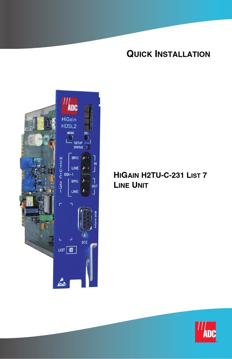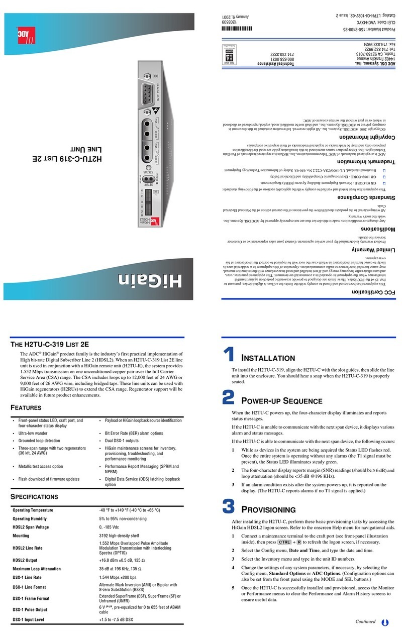
LOOPBACK TESTING
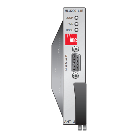
Initiate loopback testing from the maintenance terminal screen or use the MODE and LBK
pushbuttons. The in-band codes below (except COLB, and RULB) can also be sent by a test
set.
Copies of this publication or the technical practice (LTPH-TP-1072-xx) can be downloaded
from the ADC website at www.adc.com. To order a hard copy, please contact your sales
representative.
Craft port provisioning
To access all system maintenance, provisioning,
and performance screens, connect a standard
9-pin terminal cable between the serial port on a
PC and the H2TU-C craft port.
9600 baud
8 data bits
No parity
1 stop bit
Hardware flow control: OFF
Terminal emulation: VT100
MaintenanceTerminal Modem Settings
Card-Edge Connector
Reports the following conditions:
Front-panel display
Status LED
Displays status, provisioning,
and alarm messages. See tables
below for message descriptions.
27
25
23
21
19
17
15
13
11
9
7
3
5
1
Networkmanagement bus
Burnin/Factory use only
Circuit ground
(-)
(+)
DSX-1XMT
Tip
Fusealarm
28
26
24
22
20
18
16
14
12
10
8
4
6
2
55
53
51
49
47
45
43
41
39
37
35
32 31
56
54
52
50
48
46
44
42
40
38
36
34
30
33
29
Note: Active pins are highlighted in black.
HDSL2Span
DSX-1RCV
-48Vdc local power
Chassis ground*
Alarm
Ring1
Tip1
Ring
Tip
Ring
Factoryuseonly
* Chassis ground must be connected to earth or neutral ground
according to local practice.
HiGain
HDSL2
XMT
D
S
X
1
BRG
RCV
H
2
T
U
*
C
2
0
2
H
D
S
L
2
M
O
D
E
STATUS
L
B
K
RS-232
DCE
L
2F
List number
Mode and LBK pushbutton options
Use the MODE and LBK pushbuttons to review all system
parameters, including user-configured settings, and to
activate loopbacks.
To display system parameters: Press the MODE pushbutton
for at least 3 seconds to place the front-panel display in Scroll
mode.When it has finished scrolling through all the system
parameters, the display returns to its normal mode.
To initiate a dual loopback: Press the LBK pushbutton for
more than 3 seconds to activate both the NLOC and CREM
loopbacks.If a loopback condition already exists, this will
loop down all existing loopbacks.Press the LBK pushbutton
again for more than 3 seconds to reactivate the dual loopback.
To initiate a manual loopback:
DSX-1 access jacks
Connect standard test equipment.
BRG Provides non-intrusive bridging jack
access to (XMT) and from (RCV)
the HDSL2 span at the DSX-1 interface.
Allows monitoring of the DS1 payloads.
1Press both MODE and LBK pushbuttons for at least
5 seconds.The following message appears:
2 Press LBK to activate the NLOC loopback or press
MODE to advance to the next loopback selection.
MAN LBK NLO?
• Green LED:
Normal operation
• Red LED:
Fuse alarm
•Yellow LED:
Customer remote (CREM) or network
local (NLOC) loopback is in effect.
• Flashing Red LED:
HDSL2 acquisition or
system alarm
• Off:
Line power is off.
• FlashingYellow LED:
System is in Armed (ARM) mode.
To manually terminate a loopback: Press both MODE and
LBK for 3 or more seconds.
GNLB Loopback Commands
Loopback In-band Code Description
NLOC 1111000 DSX-1 signal is looped back to the network at the H2TU-C.
NREM 1110000 DSX-1 signal is looped back to the network at the H2TU-R.
COLB(a)
(a) Dual loopbacks are only initiated from the MODE and LBK pushbuttons.
DSX-1 signal is looped back to the network at the H2TU-C and signal from
the customer is looped back to the customer at the H2TU-C.
RULB (a) DSX-1 signal is looped back to the network at the H2TU-R and signal from
the customer is looped back to the customer at the H2TU-R.
CREM 1111110 DS1 signal from customer is looped back to the customer at the H2TU-C.
CLOC 1111100 DS1 signal from customer is looped back to the customer at the H2TU-R.
SMJK 11000 DSX-1 signal is looped back to the network at the H2TU-R SmartJack
module.
Loopdown 11100 Deactivates any of the above loopbacks.
Front-Panel Alarm Messages (a)
(a) Front-panel alarm messages are listed in order of priority. ALRM displays prior to any alarm message.
Pressing the LBK pushbutton initiates an Alarm Cutoff (ACO) message.
Message Description (listed in priority order)
PWR FEED SHRT (b)
(b) Message displays repeatedly as long as the alarm condition exists, and is not included in the priority order.
A short between the Tip and Ring of the HDSL2 pair.
PWR FEED GND (b) The HDSL2 loop is grounded.
PWR FEED OPEN (b) A line-power open condition.
SPN1-LOSW The HDSL2 loop has lost synchronization. The span closest to the network has
highest priority.
LLOS No signal is detected at the DSX-1 input to the H2TU-C.
RLOS No signal is detected at the DS1 input to the H2TU-R.
LAIS (c)
(c) Does not activate the alarm relay access pins 30 and 22.
Line Alarm Indication Signal.
RAIS (c) Remote Alarm Indication Signal.
TRCI An RAI alarm (yellow) from the CPE with an error-free signal from the line unit or
network.
RRAI An RAI alarm (yellow) from the Customer Premises Equipment (CPE) with errors
from the line unit or network.
xxx-DBER A system DS1 Bit Error Rate (BER) alarm. (xxx denotes either TUC or TUR.)
PRMF H2TU-R Performance Report Messaging BER threshold exceeded at far end.
PRMN H2TU-R Performance Report Messaging BER threshold exceeded at near end.
xxx-HBER A system HDSL2 Block Error Rate (BER) alarm. (xxx denotes either TUC or TUR.)
xxx-MAL The margin on the HDSL2 loop has dropped below the threshold setting. (xxx denotes
either TUC or TUR.)
xxx-LA The attenuation on the HDSL2 loop has exceeded the maximum threshold value.
(xxx denotes either TUC or TUR.)
To comply with the intrabuilding wiring requirements of GR-1089
CORE, Section 4.5.9, the shields of the ABAM-type cables that
connect the H2TU-C-202 List 2F DSX-1 output ports to the
cross-connect panel must be grounded at both ends.
Network
Customer
Premises
H2TU-C H2TU-R
TLOS*
NLOC CREM CLOC
1111000 NREM
1110000 1111100
1111110
11000
SMJK
When enabled,TLOS is an automatic loopback
that occurs with an LOS at the remote DS1 input.
*
DS1DSX-1
Front-Panel Diagnostic Messages
Message Description (normal operating messages in bold)
A=xx The loop attenuation of the longest (maximum loss) span, measured in dB.
ACQ The multiplexers of the H2TU-C and H2TU-R are trying to establish synchronization.
ARM Armed to respond to Intelligent Repeater Loop (ILR) codes.
BAD RT? The H2TU-C is not receiving a response from the H2TU-R.
FERR A framing bit error occurred at H2TU-C DSX-1 input.
HES H2TU-C HDSL2 loop cyclical redundancy check (CRC) error.
LBPV A local bipolar violation has been received at the DSX-1 input to the H2TU-C.
M=xx Indicates the power of the received HDSL2 signal relative to noise (S/N with respect to
21.5 dB). Any value of 6 dB or greater is adequate for reliable system operation.
MNGD The H2TU-C is under control of the HMU-319 network management unit.
PWR FEED OFF HDSL2 span power is turned off.
PWR FEED ON Indicates that the HDSL2 loop is not grounded or shorted.
SIG The transceivers of the H2TU-C and H2TU-R are trying to establish contact with each
other on Span 1 of the HDSL2 loop.
Front-Panel Read-Only Settings Using MODE (a)
(a) To scroll, press the MODE pushbutton for 3 seconds. Front-panel codes scroll in the order listed. The
configured selections follow each code.
Message Description (default selections in bold)
VER x.xx Software version number of the H2TU-C-202.
LIST xx List number of the H2TU-C-202.
FRM xxxx Frame pattern received from the DSX-1 (SF, ESF, UNFR).
CODE xxxx Line code (AMI or B8ZS).
LATT xx Loop Attenuation threshold setting (38 dB).
MARG xx Margin threshold setting (4 dB).
EQL Indicates DSX-1 Equalizer setting: 0 (0 to 132 ft.), 133 (133 to 265 ft.), 266 (266 to 398 ft.),
399 (399 to 532 ft.), 533 (533 to 655 ft.).
RLBO Indicates H2TU-R line buildout setting: 0 dB, -7.5 dB, or -15 dB.
LPBK SmartJack loopback commands enabled (ENA) or disabled (DIS).
SPLB xxxx System configuredfor generic (GNLB)or specialin-bandloopback commands (A1LB, A2LB,A3LB,
A4LB, A5LB).
PWRF HDSL2 line power disabled (OFF) or -180 Vdc (ON).
HBER 1E-6 or 1E-7 = indicates HDSL2 BER alarm threshold setting. NONE = no generation of a
system alarm due to BER.
DBER 24-hour DSX-1 BER alarm threshold enabled (ENA) or disabled (DIS).
LBTO Loopback timeout = NONE, 20, 60, 120 minutes, 8-hour, 24-hour.
ALM Enables (ENA) or disables (DIS) alarm indications on pins 30 and 22.
DS1 DSX-1 line code = Bipolar with 8-Zero Substitution (B8ZS), Alternate Mark Inversion (AMI).
CONV H2TU-R frame format conversion = OFF (framing determined by the DS1 FRMG option),
ACON (autodetection of framing and potential frame conversion at the H2TU-R), or
FCON (autodetection of framing and forced frame format conversion at the H2TU-R).
FRMG DS1 frame formatting = AUTO (auto framing mode) or UNFR (unframed mode),
RDA Alarm indications due to remote DS1 LOS at H2TU-R input are enabled(ENA) or disabled
(DIS).
ALMP Alarm pattern = Alarm Indication Signal (AIS) or Loss of Signal (LOS).
BPVT Bipolar Violation Transparency (BPVT) enabled (ENA) or disabled (DIS).
NLBP H2TU-R transmits either AIS or LOS towards CI for any network loopback.
TLOS Logic loopback at the H2TU-R is either enabled(ENA) or disabled (DIS) when an LOS occurs
at its DS1 input.
PRM Performance Report Messaging = OFF (no enhanced Performance Report Messaging), SPRM
(Supplemental PRM), NPRM (Network PRM), AUTO (H2TU-R generates both SPRMs and
NPRMs whenever possible).
NAIS If ALMP is set to AIS, indicates which pattern is sent to the network when a remote LOS
or AIS occurs. CI = AIS-CI sent to the network; AIS = AIS sent to the network.
ROVR Conversion of an ESF DS1 payload from the network with an embedded RAI pattern to an
SF-RAI pattern toward the CI at the H2TU-R is enabled (ENA) or disabled (DIS). CONV
option must be set to FCON or ACON.
RACI Conversion of a DS1 RAI signal (yellow alarm) received by the H2TU-R to an RAI-CI signal
toward the network is enabled (ENA) or disabled (DIS).
PBOC Indicates the power output levels of the H2TU-R customer unit toward the network.
Default (DEF) or enhanced (ENH).
PBON Indicates the power output levels of the H2TU-C network unit toward the customer.
Default (DEF) or enhanced (ENH).
