B+K precision 4076 User manual

Model: 4076, 4079
50 MHz Arbitrary Function Generator
USER MANUAL

2
SERVICE INFORMATION
Warranty Service: Please go the support and service section on our website www.bkprecision.com to obtain a RMA #. Return the
product in the original packaging with proof of purchase to the address below. Clearly state on the RMA the performance problem and
return any leads, probes, connectors and accessories that you are using with the device.
Non-Warranty Service: Please go the support and service section on our website www.bkprecision.com to obtain a RMA #. Return the
product in the original packaging to the address below. Clearly state on the RMA the performance problem and return any leads, probes,
connectors and accessories that you are using with the device. Customers not on an open account must include payment in the form of a
money order or credit card. For the most current repair charges please refer to the service and support section on our website.
Return all merchandise to B&K Precision Corp. with pre-paid shipping. The flat-rate repair charge for Non-Warranty Service does not
include return shipping. Return shipping to locations in North America is included for Warranty Service. For overnight shipments and
non-North American shipping fees please contact B&K Precision Corp.
B&K Precision Corp.
22820 Savi Ranch Parkway
Yorba Linda, CA 92887
www.bkprecision.com
714-921-9095
Include with the returned instrument your complete return shipping address, contact name, phone number and description of
problem.
LIMITED THREE-YEAR WARRANTY
B&K Precision Corp. warrants to the original purchaser that its products and the component parts thereof, will be free from defects in
workmanship and materials for a period of three years from date of purchase.
B&K Precision Corp. will, without charge, repair or replace, at its option, defective product or component parts. Returned product must
be accompanied by proof of the purchase date in the form of a sales receipt.
To obtain warranty coverage in the U.S.A., this product must be registered by completing a warranty registration form on our website
www.bkprecision.com within fifteen (15) days of purchase.
Exclusions: This warranty does not apply in the event of misuse or abuse of the product or as a result of unauthorized alterations
or repairs. The warranty is void if the serial number is altered, defaced or removed.
B&K Precision Corp. shall not be liable for any consequential damages, including without limitation damages resulting from loss of use.
Some states do not allow limitations of incidental or consequential damages. So the above limitation or exclusion may not apply to you.
This warranty gives you specific rights and you may have other rights, which vary from state-to-state.
B&K Precision Corp.
22820 Savi Ranch Parkway
Yorba Linda, CA 92887
www.bkprecision.com
714-921-9095

3
Safety Summary
The following safety precautions apply to both operating and maintenance personnel and must be
observed during all phases of operation, service, and repair of this instrument. Before applying power,
follow the installation instructions and become familiar with the operating instructions for this
instrument.
Failure to comply with these precautions or with specific warnings elsewhere in this manual violates
safety standards of design, manufacture, and intended use of the instrument. B&K PRECISION
assumes no liability for a customer’s failure to comply with these requirements. This is a Safety Class I
instrument.
GROUND THE INSTRUMENT
To minimize shock hazard, the instrument chassis and cabinet must be connected to an electrical
ground. This instrument is grounded through the ground conductor of the supplied, three-conductor ac
power cable. The power cable must be plugged into an approved three-conductor electrical outlet. Do
not alter the ground connection. Without the protective ground connection, all accessible conductive
parts (including control knobs) can render an electric shock. The power jack and mating plug of the
power cable meet IEC safety standards.
DO NOT OPERATE IN AN EXPLOSIVE ATMOSPHERE
Do not operate the instrument in the presence of flammable gases or fumes. Operation of any electrical
instrument in such an environment constitutes a definite safety hazard.
KEEP AWAY FROM LIVE CIRCUITS
Instrument covers must not be removed by operating personnel. Component replacement and internal
adjustments must be made by qualified maintenance personnel. Disconnect the power cord before
removing the instrument covers and replacing components. Under certain conditions, even with the
power cable removed, dangerous voltages may exist. To avoid injuries, always disconnect power and
discharge circuits before touching them.
DO NOT SERVICE OR ADJUST ALONE
Do not attempt any internal service or adjustment unless another person, capable of rendering first aid
and resuscitation, is present.
DO NOT SUBSTITUTE PARTS OR MODIFY THE INSTRUMENT
Do not install substitute parts or perform any unauthorized modifications to this instrument. Return the
instrument to B&K Precision for service and repair to ensure that safety features are maintained.
WARNINGS AND CAUTIONS
WARNING and CAUTION statements, such as the following examples, denote a hazard and appear
throughout this manual. Follow all instructions contained in these statements.
A WARNING statement calls attention to an operating procedure, practice, or condition, which, if not
followed correctly, could result in injury or death to personnel.
A CAUTION statement calls attention to an operating procedure, practice, or condition, which, if not
followed correctly, could result in damage to or destruction of part or all of the product.
WARNING:
Do not alter the ground connection. Without the protective ground connection, all
accessible conductive parts (including control knobs) can render an electric shock.
The power jack and mating plug of the power cable meet IEC safety standards.
WARNING:
To avoid electrical shock hazard, disconnect power cord before removing covers.
Refer servicing to qualified personnel.

4
CAUTION:
Before connecting the line cord to the AC mains, check the rear panel AC line
voltage indicator.
Applying a line voltage other than the indicated voltage can
destroy the AC line fuses. For continued fire protection, replace fuses only with
those of the specified voltage and current ratings.
CAUTION:
This product uses components which can be damaged by electro-
static discharge
(ESD). To avoid damage, be sure to follow proper procedures for handling, storing
and transporting parts and subassemblies which contain ESD-
sensitive
components.

5
Table of Contents
Safety Summary .............................................................................................. 3
Section 1 .......................................................................................................... 7
Introduction........................................................................................................................ 7
1.1 Introduction..............................................................................................................................................7
1.2 Description...............................................................................................................................................7
1.3 Memory Architecture ............................................................................................................................... 7
1.4 Package Contents ................................................................................................................................... 8
Specifications..................................................................................................................... 8
Modulation Combinations............................................................................................... 10
Section 2 ........................................................................................................ 11
Installation........................................................................................................................ 11
2.1 Introduction............................................................................................................................................11
2.2 Mechanical Inspection...........................................................................................................................11
2.3 Initial Inspection.....................................................................................................................................11
2.4 Instrument Mounting.............................................................................................................................. 11
2.5 Product Dimensions ..............................................................................................................................11
2.6 Power Requirements.............................................................................................................................12
2.7 Grounding Requirements ......................................................................................................................12
2.8 Signal Connections................................................................................................................................ 12
2.9 RS-232 Connection ...............................................................................................................................12
2.10 RS-232 Configuration...........................................................................................................................13
2.11 GPIB Address.......................................................................................................................................14
2.12 GPIB Connections............................................................................................................................... 14
Section 3 ........................................................................................................ 15
Operating Instructions .................................................................................................... 15
3.1 General Description...............................................................................................................................15
3.2 Display Window....................................................................................................................................16
3.3 Front Panel Controls.............................................................................................................................. 17
3.4 Back Panel Controls..............................................................................................................................17
3.5 Output connectors .................................................................................................................................19
3.6 MENU Keys...........................................................................................................................................19
3.7 ON Key .................................................................................................................................................. 35
3.8 Cursor Movement Keys.........................................................................................................................35
3.9 Rotary Input Knob..................................................................................................................................35
3.10 Power-On Settings ..............................................................................................................................35
3.11 Memory................................................................................................................................................36
3.12 Displaying Errors .................................................................................................................................36
3.13 Using The Model 4076 and 4079 ........................................................................................................37
3.14 Examples.............................................................................................................................................38
Section 4 ........................................................................................................ 44
Programming.................................................................................................................... 44
4.1 Overview................................................................................................................................................44
4.2 Device State .......................................................................................................................................... 45
4.3 Interface Function Subsets....................................................................................................................46
4.4 Device Address......................................................................................................................................46

6
4.5 Message Exchange Protocol.................................................................................................................46
4.6 Block Data (GPIB Only).........................................................................................................................47
4.7 Instrument Identification ........................................................................................................................47
4.8 Instrument Reset ...................................................................................................................................47
4.9 Self Test.................................................................................................................................................47
4.10 Command Syntax................................................................................................................................ 48
4.11 Status Reporting..................................................................................................................................51
4.12 Common Commands...........................................................................................................................56
4.13 Instrument Control Commands............................................................................................................60
4.14 IEEE 488.1 Interface Messages..........................................................................................................89
4.15 SCPI Command Tree..........................................................................................................................90
4.16 Block Transfer (GPIB only)..................................................................................................................95
4.17 GPIB Communication Protocol............................................................................................................96

7
Section 1
Introduction
1.1 Introduction
This manual contains information required to operate, program and test the Model 4076 and 4079 – 50 MHz DDS
Arbitrary Function Generators. This section covers the instrument general description, instrument specifications and
characteristics.
1.2 Description
The Model 4076 and 4079 are versatile high performance arbitrary waveform generators. Arbitrary waveforms can be
programmed and generated with 14 bit resolution and up to 4,000,000 points length. Waveforms can be output in
continuous, triggered, gated or burst mode. AM and FM modulation combined with versatile Sweep capabilities make
the unit suitable for a wide range of applications. Editing is flexible and easy including auto increment, line draw and
predefined waveform facilities. The instrument can be remotely operated via the RS232 or GPIB interface and they are
SCPI compatible.
1.3 Memory Architecture
The waveform memory consists of 4,000,000 points. The user can edit arbitrary waveforms in waveform memory and
can specify any data value in the range from -8191 to 8191 for any point in waveform memory (14 bit depth).Due to
their large memory bank, the 4076 and 4079 can essentially give the user greater freedom in selecting the size of their
waveforms and the number of waves they desire to generate, with the limit of 4,000,000 total points when added
together.
For example, these generators can create a waveform with 100,000 points, another waveform with 500,000 points, a
third waveform with 400,000 points, and a fourth waveform with 3,000,000 points. These four waveforms total up to
4,000,000 points, but essentially they can be referenced in the memory bank according to their starting point and their
length. There are no restrictions as to how many different waveforms you can store in the memory, so as long as the
sum of the points of all the waveforms do not exceed 4,000,000 points. To better illustrate this, refer to drawing
below:
The following operations can be performed in the waveform memory:
- Insert and scale any of the following predefined waveforms:
1
4,000,000
Waveform 1
Waveform …
Waveform 2
Waveform 3
A pts.
B pts.
C pts.
D pts.
A pts. + B pts. + C pts. + D pts. ≤4,000,000 pts.
Point
Point

8
oSine
oTriangle
oSquare
oRamp up
oRamp down
oNoise
- Draw a line between any two points
- Clear (set to zero) any set of points or all points
- Protect any set of points or all points from being changed or erased
- Copy any set of points to another area in the memory
- Set individual point values
After specifying a section of waveform memory for execution, the following parameters of the waveform can be
configured:
- Point rate (frequency)
- Peak-to-peak amplitude
- Offset voltage
1.4 Package Contents
The following list of items and accessories come in the package:
1. 4076 or 4079 DDS Function Generator
2. AC power cord
3. CD containing user manual and waveform creation software Wave-X
4. RS232 Serial Cable
Specifications
Models
4076
4079
Channels
1 Channel
2 Channels
Frequency
Characteristics
Sine
1 uHz to 50 MHz
Square
1 µHz to 50 MHz
Triangle, Ramp
1 µHz to 5 MHz
Pulse
0.5 mHz to 25 MHz
Accuracy
0.001 % (10 ppm)
Resolution
12 digits or 1 µHz
Arbitrary
Characteristics
Built-in Waveforms
Sine, Triangle, Square, Noise, Ramp Up, Ramp Down,
Sine(X)/X, Exponential Up, Exponential Down,
Gaussian
Waveform Length
2 points to 4,000,000 points
Vertical Resolution
14 bits (16,384 levels)
Noise
Add 1% to 100% to output waveform
Sampling Rate
125 MSa/s, Point execution rate: adjustable from 8 ns
to 100 s
Frequency Accuracy
0.001% (10 ppm)
Frequency Resolution
4 digits or 1 ps
Output
Characteristics
Amplitude Range
10 mV to 10 Vp-p into 50 ohms
Amplitude Resolution
3 digits (1000 counts)
Amplitude Accuracy (at 1 kHz)
± 1% ± 20 mV of programmed output from 1 V – 10 V
Flatness (relative to 1 kHz)
± 0.1 dB to 10 MHz
± 1 dB to 50 MHz

9
Offset Range
± 4.99 V into 50 Ω, depending on the Amplitude setting
Offset Resolution
10 mV with 3 digits resolution
Offset Accuracy
± 1% ± 10 mV into 50 Ω
Output Impedance
50 Ω typical
Output Protection
The instruments output is protected against short
circuit or nominal accidental voltages applied to the
main output connector
Filters
9 pole Elliptic and 5 pole Bessel filters
Waveform
Characteristics
Harmonic Distortion (sine)
DC-20 kHz, -65 dBc
20 kHz-100 kHz, 60 dBc
100 kHz-5 MHz, -45 dBc
5 MHz-50 MHz, -35 dBc
Spurious (sine)
DC-1 MHz < -65 dBc
Rise/Fall Time (square, pulse)
< 6 ns (10% to 90%) at full amplitude into 50 Ω
Variable Duty Cycle
20% to 80% to 10 MHz (square)
40% to 60% to 30 MHz (square)
50% >30 MHz (square)
Variable Symmetry
10%-90% to 5 MHz (triangle)
Symmetry at 50%
< 0.5 %
Linearity (triangle, ramp)
<0.1 % of peak output (1 µHz to 250 kHz)
Aberrations
< 3 % of p-p amplitude ± 50 mV
Pulse Width (period 10 μs - 0.1
μs)
20 ns to < ( Period -20 ns )
(10 ns resolution)
Variable Edge Time
(period 100 μs - 0.16 μs)
100 ns to Width/0.625 (50 % duty cycle)
10 ns resolution
Operating Modes
Continuous
Output continuous at programmed parameters
Triggered
Output quiescent until triggered by an internal or
external trigger, then one waveform cycle is generated
to programmed parameters. Up to 20 MHz trigger rate
for ARB waveforms and 10 MHz in DDS mode
Gate
Same as triggered mode, except waveform is executed
for the duration of the gate signal. The last cycle
started is completed
Burst
2-999,999 cycles
Phase
-180 to +180 degrees with 0.1 degree resolution
Trigger Source
Trigger source may be internal, external or manual.
Internal trigger rate 0.01 Hz-1 MHz (1 µs – 100 s)
Modulation
Characteristics
Amplitude
Modulation
Internal
0.01 Hz-20 kHz sine , square or triangle waveform
variable modulation from 0% to 100%
External
5 Vp-p for 100% modulation, 10 kΩinput impedance
0.01 Hz – 50 KHz bandwidth
Frequency
Modulation
Internal
0.01 Hz-20 kHz sine wave, square or triangle
External 5 Vp-p for 100% deviation, 10 kΩinput impedance,
0.01 Hz – 50 kHz bandwidth
FSK
Internal
0.01 Hz to 1 MHz
External
1 MHz max.
Sweep
Characteristics
Sweep Shape
Linear and Logarithmic, up or down
Sweep Time
10 ms to 500 s
Sweep Trigger
internal, external, continuous or burst
Inputs and
Outputs Trigger IN
TTL Compatible
Maximum rate 20 MHz
Minimum width 20ns
Input Impedance10 kΩ nominal
Sync OUT
TTL pulse at programmed frequency, 50ohms source

10
impedance
Modulation IN
5 Vp-p for 100% modulation
10 KΩinput impedance
DC to >50 kHz minimum bandwidth
Marker Out
Positive TTL pulse user programmable in Arbitrary
waveform, 50 Ωsource impedance
Reference IN-OUT 10 MHz, TTL compatible, input or output, for external
unit synchronization 50 Ωoutput impedance and 1 kΩ
input
Summing IN 5 Vp-p signal for full scale output, 500 Ω input
impedance
Internal Trigger
Repetition
1 ms to 100 s
Resolution
4 digits
Accuracy
+0.002%
General
Display Resolution
160 x 80 dots LCD
Remote Control Interface
GPIB, RS-232
Store Memory
50 full panel settings at power-off
Dimensions
8.4(213) x 3.5(88) x 11.8(300) inches (mm) (WxHxD)
Weight
Approx. 2.5 kg (5.5lbs)
Power
100-240 VAC ± 10%, < 50 VA max.
Temperature
Operating
0 ºC to +50 ºC
Non-
operating
-20 ºC to +70 ºC
Humidity
95 % RH , 0 ºC to 30 ºC
EMC According to EN55011 for radiated and conducted
emissions
Electrical Discharge Immunity
According to EN55082
Safety Specifications
According to EN61010 , CE approved
NOTE
Specifications listed in manual are applicable after a powered 30 minute warm-up
Specifications are verified according to the performance check procedures.
Specifications not verified in the manual are either explanatory notes or general performance characteristics only.
Specifications and information is subject to change without notice. For the most current and correct data please
visit www.bkprecision.com
Modulation Combinations
SINE
SQUARE
TRIANGLE
PULSE
ARBITRARY
AM
Yes
Yes
Yes
Yes
Yes
FM
Yes
Yes
Yes
No
No
FSK
Yes
Yes
Yes
No
No

11
Section 2
Installation
2.1 Introduction
This section contains installation information, power requirements, initial inspection and signal connections for
Model 4076 and 4079.
2.2 Mechanical Inspection
This instrument was carefully inspected before shipment. Upon receipt inspect the instrument for damage that might
have occurred in transit. If there is damage due to shipping, file a claim with the carrier who transported the unit.
The shipping and packing material should be saved if reshipment is required. If the original container is not to be
used, then use a heavy carton box. Wrap the unit with plastic and place cardboard strips across the face for
protection. Use packing material around all sides of the container and seal it with tape bands. Mark the box
"FRAGILE".
2.3 Initial Inspection
After the mechanical inspection, verify the contents of the shipment (accessories). If the contents are incomplete, or
if the instrument does not pass the specification acceptance tests, notify the local service center.
2.4 Instrument Mounting
The Model 4076 and 4079 - Function Generators are intended for bench use. The instrument includes a front feet
tilt mechanism for optimum panel viewing angle. The instrument does not require special cooling when operated
within conventional temperature limits. The unit can be installed in a closed rack or test station if proper air flow is
assured for removing about 20 W of power dissipation.
2.5 Product Dimensions
300 mm
213 mm
88 mm

12
2.6Power Requirements
The Model 4076 and 4079 can be operated from any source of 100 V to 265 V AC, frequency from 48 Hz to 66 Hz.
The maximum power consumption is 50 VA. Use a slow blow fuse UL/CSA approved of 1 A as indicated on the
rear panel of the instrument.
WARNING
THE LINE POWER VOLTAGE OF THE INSTRUMENT IS NOTED ON THE AC INPUT PLUG. TO
PREVENT DAMAGE TO THE INSTRUMENT, CHECK FOR PROPER MATCH OF LINE VOLTAGE
AND PROPER FUSE TYPE AND RATING.
The instrument power fuse is located in the AC input plug. To access the fuse, first disconnect the power cord and
then remove the fuse cartridge.
2.7 Grounding Requirements
For the safety of operating personnel, the instrument must be grounded. The central pin on the AC plug grounds the
instrument when properly connected to the ground wire and plugged into proper receptacle.
WARNING
TO AVOID PERSONAL INJURY DUE TO SHOCK, THE THIRD WIRE EARTH GROUND MUST BE
CONTINUOUS TO THE POWER OUTLET. BEFORE CONNECTION TO THE POWER OUTLET,
EXAMINE ALL CABLES AND CONNECTIONS BETWEEN THE UNIT AND THE FACILITY POWER
FOR A CONTINUOUS EARTH GROUND PATH.
THE POWER CABLE MUST MEET IEC SAFETY STANDARDS.
2.8 Signal Connections
Use RG58U 50 Ωor equivalent coaxial cables for all input and output signals to and from the instrument.
2.9RS-232 Connection
The rear panel RS-232 connector is a standard DB-9 male connector configured as a DCE. The pin assignments
are defined in the table below:
13
DB-9 pin
Name
Note
1
2
3
4
5
6
7
8
9
-
TXD
RXD
-
GND
-
RTS
CRS
-
-
Transmit Data
Receive Data
-
Signal ground
-
Request to Send
Clear to send
-
*Note: Use a Null-modem or cross over cable (pin 2 and 3 switched) in order to communicate with instrument. When
transmitting large files via RS232, highest baud rate setting of 38400 is recommended, and number of data points of
transfer at any instance should not exceed 1,000,000 points. If 4,000,000 points are required, multiple transfers are
recommended; each time transferring 100,000 points. For optimal speed in transferring large files, GPIB interface is
recommended using block transfer (see Programming Section of this manual).
2.9.1 Communication Speed Chart
The 4076 and 4079 have the capabilities of generating large arbitrary waveforms with up to 4,000,000 points. Due
to this nature, the time it takes to transmit these large waveforms may vary depending on the baudrate and cable used
for RS232 interface. As a general reference, provided below is a chart that shows the approximate amount of time it
takes to download or send the waveforms of the indicated sizes at the rated baudrate speed.
Number of data pts.
Baudrates (bps) 400,000 points 1,000,000 points
38400
~30 mins
(sending)
~15 mins
(receiving)
~1hr (sending)
~30mins (receiving)
2.10 RS-232 Configuration
The instrument use 8 data bits, 1 stop bit, no parity and baud rate selectable from 2400 to 38.4K (2400, 4800,
9600, 19200, 38400). By default, the instrument is set at 9600-8-N-1.
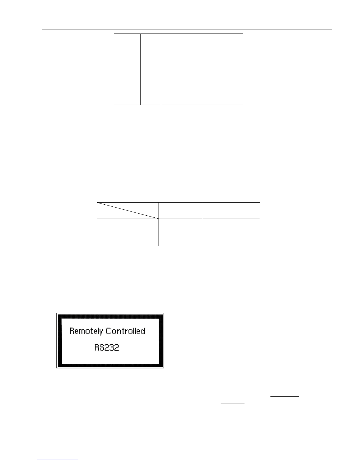
When the instrument is in remote mode, it will display the following screen:
This screen comes up whenever there is a transmission process, be it sending or receiving. To return to local mode
and exit this screen, simply press any front panel keys. Only do this when nothing is being transmitted or received
from a connected PC. In the case where a large waveform is being transmitted, please allow AT LEAST 15
seconds or more after the PC software or program has finished sending BEFORE pressing a key to return to local
mode. The instrument requires this time to completely finish generating/transmitting the waveform.
14
2.11 GPIB Address
The instrument is shipped with the address set to decimal 9. The address can be changed from the front panel by using the
"UTILITY" menu.
2.11.1 Communication Speed Chart
The 4076 and 4079 have the capabilities of generating large arbitrary waveforms with up to 4,000,000 points. As
a general reference, the GPIB interface can send and receive 1,000,000 points within less than 12 minutes.
Note: When GPIB is used, transferring in blocks of 100,000 points at a time is recommended to avoid any transfer
errors.
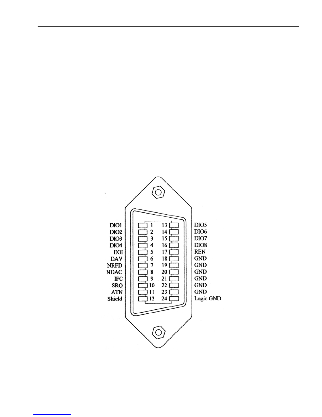
2.12 GPIB Connections
The rear panel GPIB connector is an AMPHENOL 57-10240 or equivalent, and connects to a standard IEEE-488
bus cable connector. The GPIB line screens are not isolated from chassis and signal ground.

15
Section 3
Operating Instructions
3.1 General Description
This section describes the displays, controls and connectors of the Model 4076 and 4079 - Function Generators.
All controls for the instrument local operation are located on the front panel. The connectors are located on both
front and rear panels.
Figure 3.1 - Front Panel View
1. Power ON-OFF - Applies and removes AC power to the unit
2. Display Window - Displays all instrument data and settings on a LCD.
3. FI-F5 Keys - Select the menu options that appear on the bottom section of the LCD display.
4. Function Keys - Select menu options for waveform parameters (PARAM), waveform type
(WAVE), mode of generator (MODE), sweep function (SWEEP), modulation
function (MODUL), and setup configurations (SETUPS).
1
2
3
7
8
9
11
14
5
6
15
16
12
10
4
13
(for Model 4076)
(Model 4079 only)

16
5. Numerical Keypad - Numeric entry keys for entering values for various functions and modes
6. Unit Setting Keys - Quick keys for setting units for frequency, time, and amplitude
7. Rotary Knob - Used to increment/decrement numerical values or to scan through the possible
selections.
8. Cursor Keys - Used to move the cursor (when visible) to either left or right when modifying
values of various parameters.
9. Output ON - Controls the main output signal. The output status is ON when display shows
“Out On” (for model 4076) or “On” (for model 4079).
10. Channel Output - (model 4079 only) Dual BNC channel outputs (50 Ω) of function signals.
11. Output ON - (model 4076) Controls the main output signal. The output status is ON when
illuminated.
12. Channel Output - (model 4076) BNC channel output.
13. Sync Out - (model 4076) Sync output, 50 Ω 5V TTL level
14. CHAN Key - (model 4079 only) Channel select key
15. UTIL Key - Selects remote interface options, LCD intensity, power settings, and summing
input.
16. ENTER Key - Used for confirming parameter adjustments and settings.
3.2 Display Window
The Model 4076 and 4079have graphic LCD displays that can display up to 160 x 80 dots. When you power-on the
unit a parameter (Frequency) and its current settings appear in the display. The bottom displays a menu that corresponds to
the function, parameter or mode display selected.
Figure 3.2 - LCD Display Screen
1. Channel/Output Display - Displays the current selected channel (when highlighted).
(For model 4079 only).Also displays highlighted text “Out On”
when output is ON (For model 4076) or displays a highlighted
text “On” next to “Ch 1” and/or “Ch 2” when either or both
channel outputs are ON (For model 4079).
2. General Waveform Display - Displays the general waveform being generated in the channel.
Note: Waveform shown is approximated and scaled down.
It does not show the exact representation of the waveform at
1
2
3
4
5
6
7

17
the output.
3. Frequency/ Sweep Mode Display - Displays the frequency values currently set to. In sweep mode,
it displays the sweeping type (Linear or Logarithmic).
4. Menu Functions Display - Displays the menu options available. Use F1-F5 keys on front
panel to select the options.
5. Menu Parameters Values Display - Displays the values of parameters selected in the menu.
Depending on the options chosen, various parameters will
display with a cursor for adjusting their values.
6. Mode Display - Displays the current mode selected. The can be continuous,
trigger, burst, or gate (displayed as CONT, TRI, BURST, or
GATE respectively). Refer to section 3.6.2 for details.
7. Wave Type Display - Displays the waveform type currently selected. It can be sine
(SINE), Square (SQU), triangle (TRI), pulse (PULSE), or
arbitrary (ARB).
3.3 Front Panel Controls
The front-panel controls select, display, and change parameter, function, and mode settings. They also include the
keys you use to program and generate arbitrary waveform output. Refer to Figure 3.1.
Use the rotary input knob and the cursor movement keys to enter data into the waveform generator.
To change a setting:
1. Press PARAM to display options in menu to control parameters.
1. Press any FUNCTION keys (F1 – F5) that lead to a required item.
2. Move cursor using CURSOR keys to the appropriate position in the numeric field (if applicable).
3.Use the rotary input or the numerical KEYPAD to change the value of the displayed item. Changes take effect
immediately.
4.In some parameter settings, the ENTER key must be pressed in order to set their numerical/setting values.
Otherwise, it may not save.
3.4 Back Panel Controls
The function generator has 11 (5 for model 4076) BNC Connectors on the rear panel where you can connect coaxial
cables. These coaxial connectors are labeled accordingly on the back panel for their respective channels and serve as
carrier lines for input and output signals delivered to and from the function generator.

18
Figure 3.3 - Back Panel View
1. Summing In - For CH 1. Use this input to apply an external analog signal to be added to the output
waveform. A 5 Vp-p signal is required for full scale output. Maximum input is ± 15 V.
2. CH1 Sync - This is the sync output of channel one. For model 4076 the sync output is in the front
panel of the instrument (see Figure 3.1).
3. Modulation In - Modulation input used for external modulation of a signal in AM/FM/FSK mode.
Maximum input is ± 15 V.
4. CH2 Sync - This is the sync output of channel two. For model 4076 the sync output is in the front
panel of the instrument (see Figure 3.1).
Model 4076
6
11
9
10
1
3
5
7
13
14
12
Model 4079
8
1
2
3
4
5
6
7
11
9
10
13
14
12

19
5. Marker Out - Use this connector to output a positive TTL pulse in Arbitrary waveform mode. The
Marker position and width can be programmed at any desired Arbitrary locations. (See section 3.6.3
for details)
6. Ref In/Out - Use this connector to input a 10 MHz TTL signal to be used as a reference clock for
the unit signal generation. A 10MHz TTL level signal is available for synchronization of external
units, when not in External Reference mode.
7. Trig In - Use this connector to apply an external trigger or gate signal, depending on the waveform
generator setting, to the generator. This connector is also used when using an external signal to
generate FSK under modulation menu. Maximum input is ± 15 V. (See section 3.6.8 for details)CH2
I/O - These are the same inputs/outputs as 1, 3, 5, and 7 and are dedicated for channel two only.
8. Rear Fan- Rear fan for internal cooling and ventilation. Do not block this area and be sure to leave
enough room for air to exhaust.
9. Fuse Box - Fuse compartment to check or replace fuse.
10. AC Power Connector - Used to connect power cable to AC line source.
11. Earth GND - This screw is the earth ground that is tied to the chassis.
12. GPIB Port - This is a standard GPIB port for remote interface.
13. RS-232 Port - This is a standard RS-232 port used for remote interface. Null modem or cross serial
cable is required to communicate with a PC via this port.
3.5 Output connectors
The waveform generator output circuits is protected against short circuit or nominal accidental voltages applied to the
main output connector . It operate as a 50 ohm voltage source working into a 50 ohms load. At higher frequencies,
non-terminated or improperly terminated output causes aberrations on the output waveform. In addition, loads less
than 50 ohms reduce the waveform amplitude, while loads more than 50 ohms increase waveform amplitude.
Excessive distortion or aberrations caused by improper termination are less noticeable at lower frequencies,
especially with sine and triangle waveforms. To ensure waveform integrity, follow these precautions:
1. Use good quality 50 ohms coaxial cables and connectors.
2. Make all connections tight and as short as possible.
3. Use good quality attenuators if it is necessary to reduce waveform amplitudes applied to sensitive circuits.
4. Use termination or impedance-matching devices to avoid reflections.
5. Ensure that attenuators and terminations have adequate power handling capabilities.
If there is a DC voltage across the output load, use a coupling capacitor in series with the load. The time constant of
the coupling capacitor and load must be long enough to maintain pulse flatness.
Impedance Matching
If the waveform generator is driving a high impedance, such as the 1 MΩinput impedance (paralleled by a stated
capacitance) of an oscilloscope vertical input, connect the transmission line to a 50 Ωattenuator, a 50 Ω
termination and to the oscilloscope input. The attenuator isolates the input capacitance of the device and terminates
the waveform generator properly.
3.6 MENU Keys
These keys select the main menus for displaying or changing a parameter, function or mode. Below is the hierarchy
and selections of the menu tree.

20
MENU TREE
-PARAM
oFREQ | RATE
oAMPL| OFST
UNITS (Only when AMPL is selected, press to toggle display in Vp-p, Vrms, dBm)
50 OHM | HI-Z
oINTCLK | EXTCLK
-WAVE
oSINE
oSQR (Duty Cycle)
oTRI (Symmetry)
oPULSE
FREQ | PERIOD
WIDTH
EQUAL EDGE
LEAD | TRAIL
PREV
oARB
START
LENGTH
MARK
•ADDR
•LENGTH
•ON | OFF
•PREV
EDIT
•POINT
oADRS
oDATA
oPREV
•LINE
oFROM
oTO
oEXEC
NO
YES
PREV
oPREV
•PREDEF
oTYPE (Predefined Waveform Type)
oFROM | DATA
oLENG
oSCALE (In %)
oEXEC
NO
YES
PREV
oEXEC (When NOISE is selected as TYPE)
ADD
NEW
EXEC
•NO
•YES
•PREV
PREV
•MORE
oCOPY
FROM
LENG
TO
EXEC
•NO
•YES
•PREV
PREV
oCLEAR
FROM
TO
This manual suits for next models
1
Table of contents
Other B+K precision Inverter manuals

B+K precision
B+K precision 4071 User manual

B+K precision
B+K precision 4051 User manual

B+K precision
B+K precision 4011A User manual

B+K precision
B+K precision 1253 User manual

B+K precision
B+K precision 4017A User manual

B+K precision
B+K precision 4005DDS User manual

B+K precision
B+K precision 4030 User manual

B+K precision
B+K precision 4001 User manual

B+K precision
B+K precision 4050B Series User manual

B+K precision
B+K precision 4052 User manual


