Date: 20.09.2018
ESchaudt GmbH, Elektrotechnik und Apparatebau, Planckstraße 8, 88677 Markdorf, Germany, Tel. +49 7544 9577-0, Fax +49 7544 9577-29, www.schaudt--gmbh.de
9990314 MA / EN
Installation Instructions
Connecting Solar systems (controller and
panel) to Schaudt- and third party systems
AIways follow the corresponding operating instruction manual.
1 Safety information 2......................................
1.1 Meaning of safety symbols 2...............................
1.2 General safety information 2...............................
2 Introduction 3............................................
2.1 Liability limitation 3.......................................
3 Introduction 3............................................
4 General and application 4..................................
5 Connecting the LT 320 in conjunction with LR 1218 6..........
5.1 LR 1218 and third party system 6...........................
5.2 LR 1218 and Schaudt EBLs with 3-pin solar connector 7.......
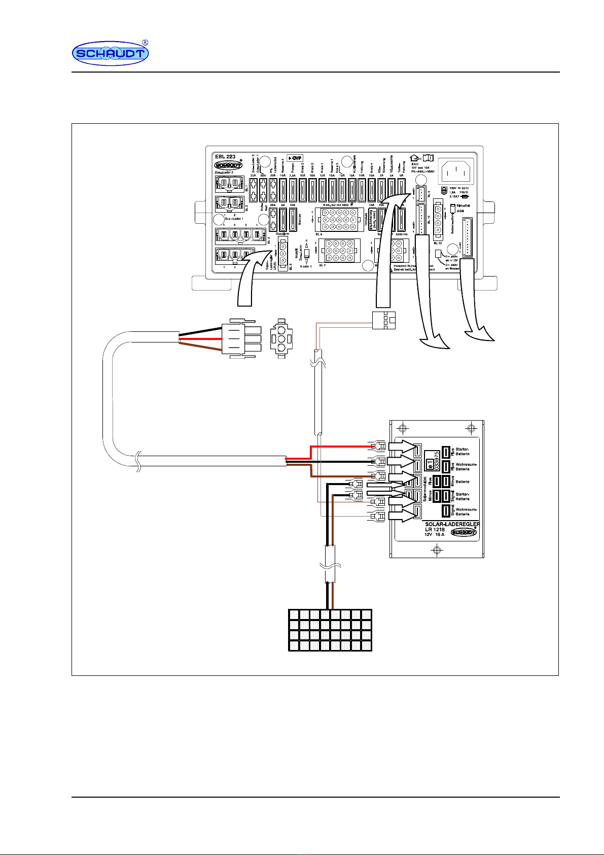
5.3 LR 1218 and Schaudt EBLs with 2-pin solar connector
and adapter for the starter battery 8.........................
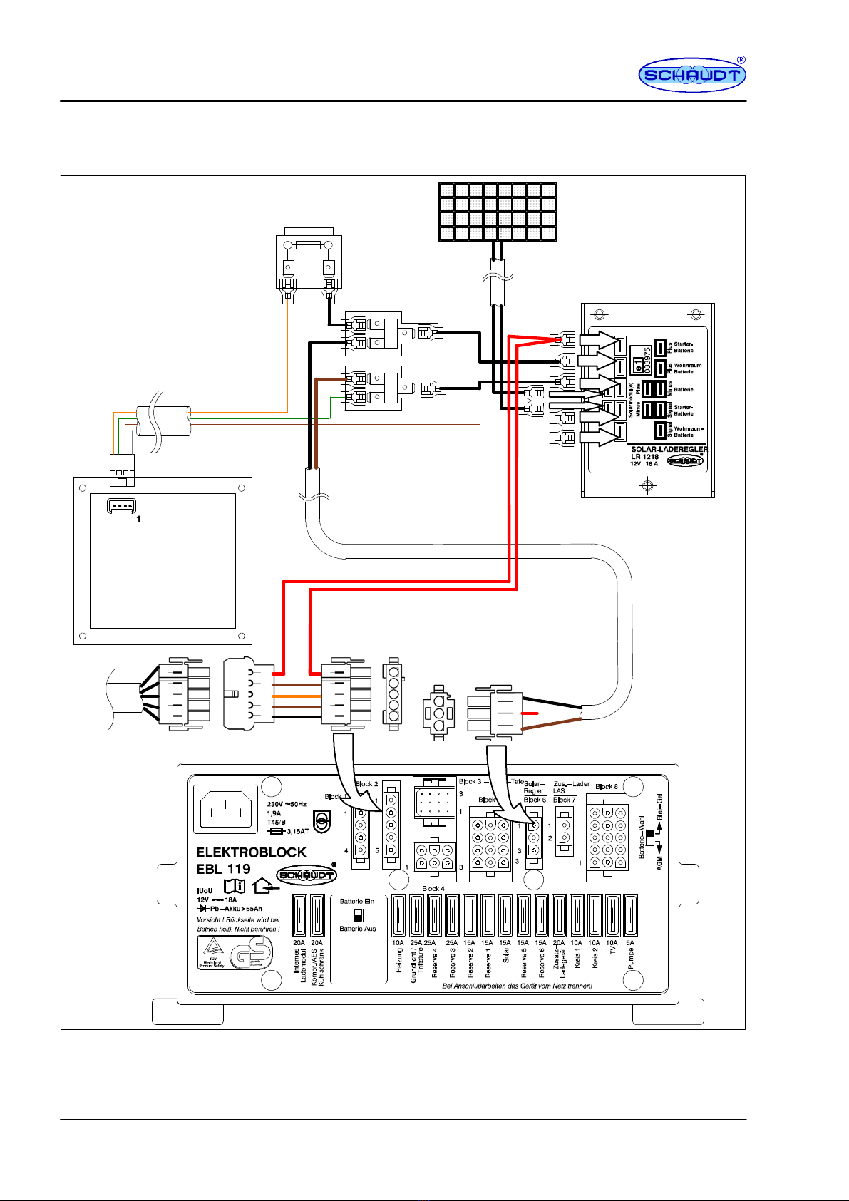
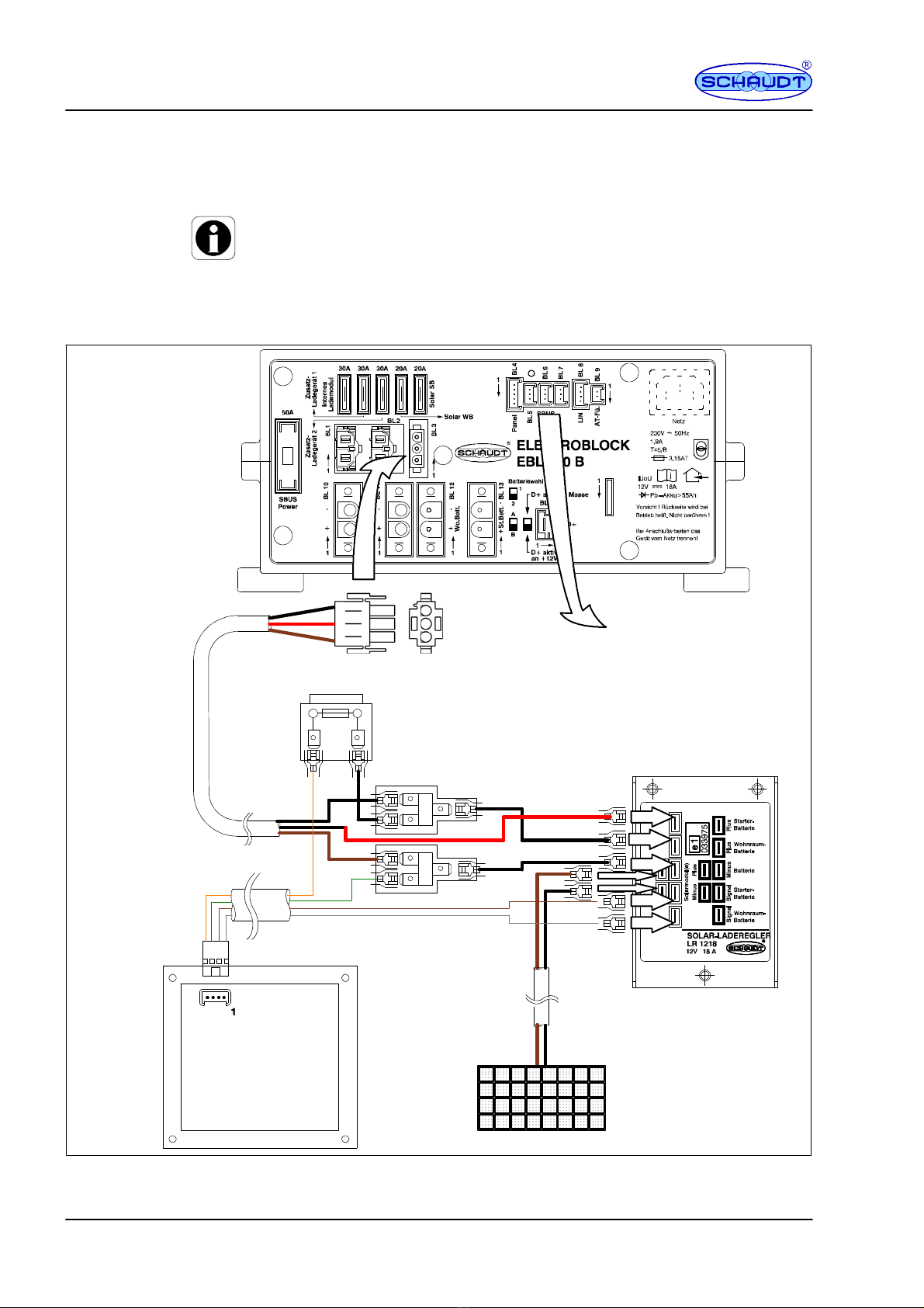
5.4 LR 1218 and Schaudt EBLs with 3-pin solar connector
and panels with solar power display 9.......................
6 Connecting the LT 320 in conjunction with LRM 1218 10........
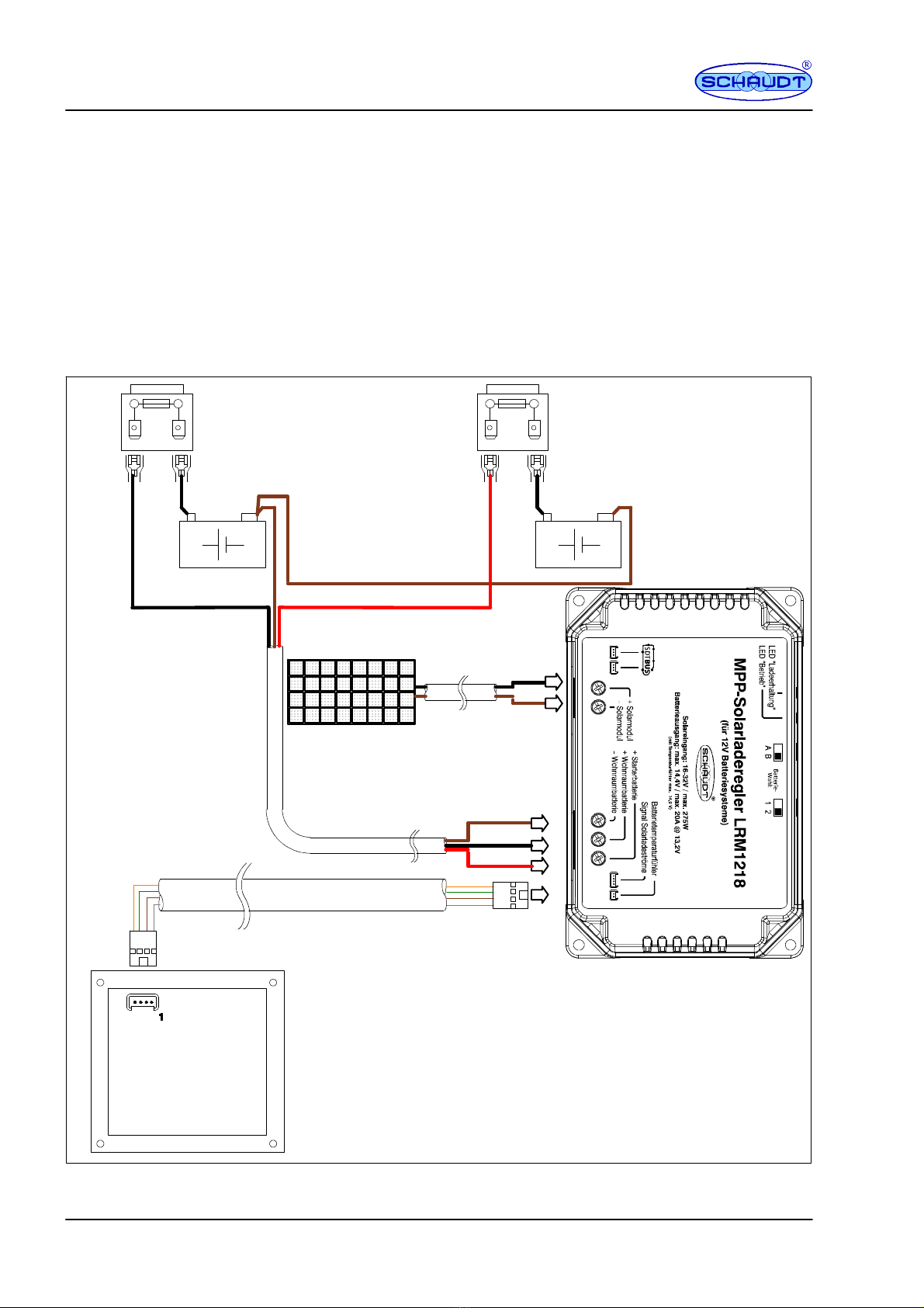
6.1 LRM 1218 and third party system 10.........................
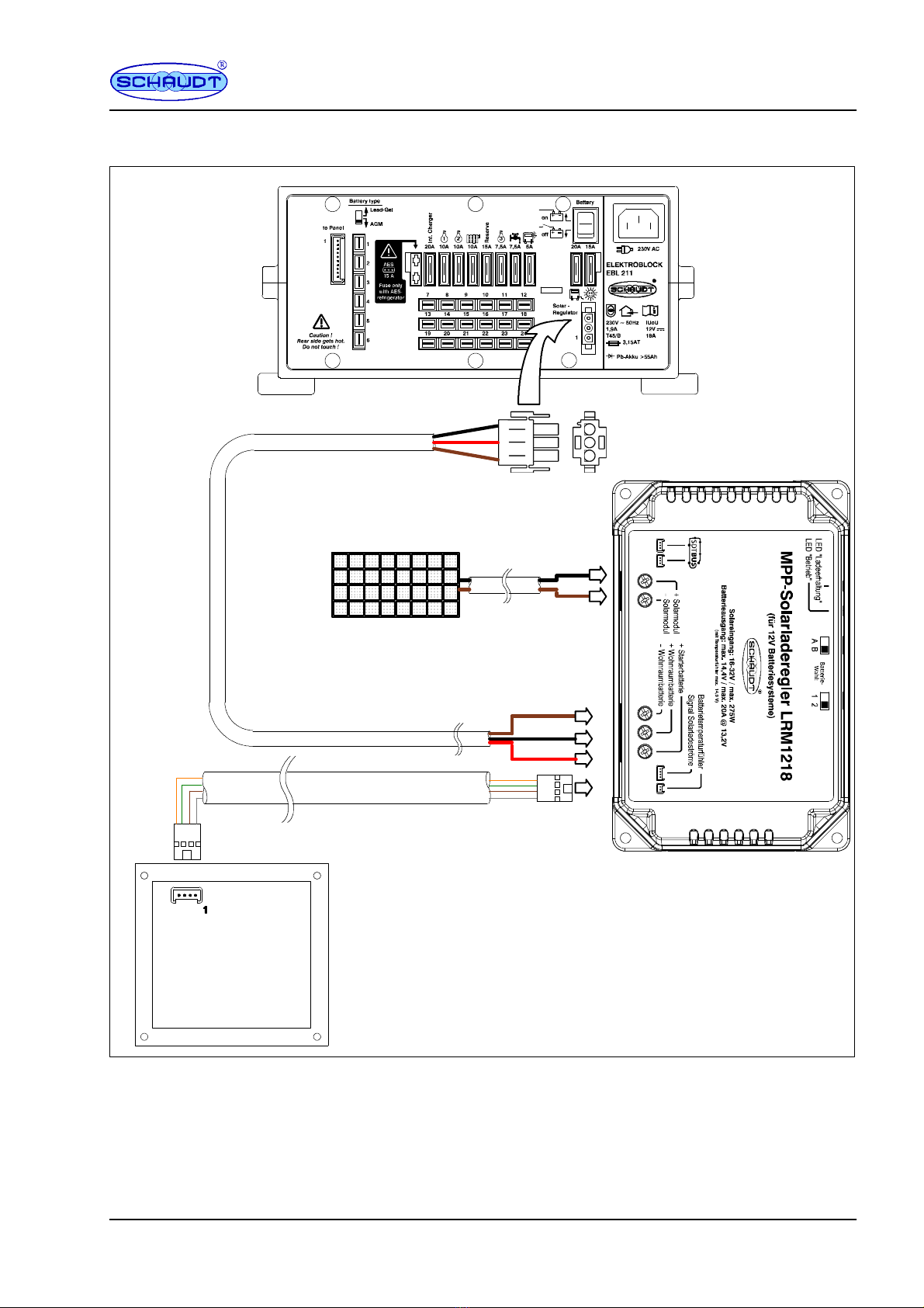
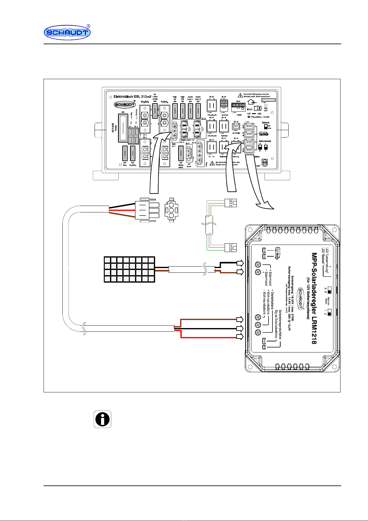
6.2 LRM 1218 and Schaudt EBLs with 3-pin
solar connector 11.........................................
6.3 LRM 1218 and Schaudt EBLs with 2-pin
solar connector and adapter for the starter battery 12...........
6.4 LRM 1218 and Schaudt EBLs with 3-pin
solar connector and panels with solar power display 13.........
7 Connecting to SDTBUS bus systems 14......................
7.1 LR 1218 with LT 320 14....................................
7.2 LRM 1218 with connection to SDTBUS 15....................
7.3 LRM 1218 with connection to SDTBUS and LT 320 16..........