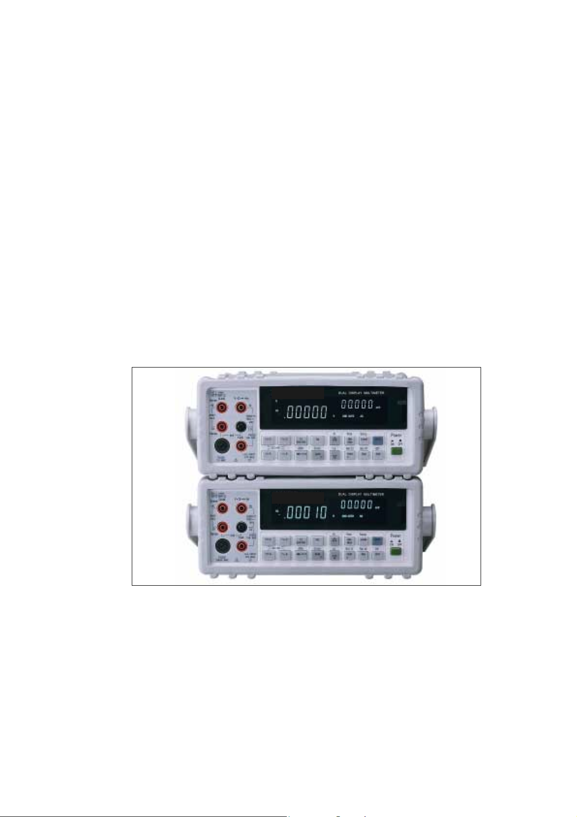
B+K precision 5492 User manual


Other manuals for 5492
1
This manual suits for next models
1
Other B+K precision Multimeter manuals

B+K precision
B+K precision 392 User manual

B+K precision
B+K precision 390B Series User manual

B+K precision
B+K precision 2712 User manual

B+K precision
B+K precision 2712 Manual

B+K precision
B+K precision 2706B User manual

B+K precision
B+K precision 878A User manual

B+K precision
B+K precision 2707B User manual

B+K precision
B+K precision 2709B User manual

B+K precision
B+K precision 2703B User manual

B+K precision
B+K precision 2705B User manual

B+K precision
B+K precision 2860A User manual

B+K precision
B+K precision 2831D User manual

B+K precision
B+K precision 5360 User manual

B+K precision
B+K precision 5492 User manual

B+K precision
B+K precision 390A User manual

B+K precision
B+K precision 2703C User manual

B+K precision
B+K precision 2880B User manual

B+K precision
B+K precision Survivor 2870 User manual

B+K precision
B+K precision 389A Test Bench User manual

B+K precision
B+K precision 5492B User manual


