Brüel & Kjær Vibro VIBROCONTROL 1500 User manual

VIBROCONTROL 1500
2-channel Monitoring Device for
Bearing Vibrations, Rolling-element Bearing
Condition and Temperature
with Diagnostic Remote Monitoring
Operating Instructions

All rights reserved.
No part of this publication may be reproduced, stored in a retrieval system or
transmitted, in any form, or by any means, electronic, mechanical,
photocopying, recording or otherwise without prior written permission from
Brüel & Kjær Vibro GmbH.
The right to make changes at any time without notice is reserved.
Copyright 2015 by Brüel & Kjær Vibro GmbH, D-64293 Darmstadt
Tel.: +49 (0)6151 428-0 Fax: +49 (0)6151 428-1000

CONTENT VIBROCONTROL 1500
VC1500EN, 13.04.2015 C103845.002 / V 09 Page 3
©Brüel & Kjær Vibro GmbH Leydheckerstr. 10 D-64293 Darmstadt
Table of Contents
VIBROCONTROL 1500
1Safety advice................................................................................ 5
2Overview ...................................................................................... 6
2.1 Display and operating elements......................................................................6
2.2 Possible measurement and monitoring tasks .................................................7
2.2.1 Display values ...........................................................................................................................7
2.2.2 Measuring range limits ..............................................................................................................8
2.2.3 Display value and bandwidth.....................................................................................................8
2.2.4 Signal detection.........................................................................................................................8
2.3 General ...........................................................................................................9
2.4 Relay functions ...............................................................................................9
3Technical Data ........................................................................... 11
4Installation.................................................................................. 16
4.1 With the installation of the VIBROCONTROL 1500 the following are to be
observed: ......................................................................................................16
4.2 Mounting in an AC-211x protective housing .................................................17
4.2.1 Delivery specifications VIBROCONTROL 1500 unit in a protective housing AC-211x ...........18
5Connections ............................................................................... 20
5.1 Connection terminal layout -upper terminal strip, 1st row...........................21
5.2 Connection terminal layout -upper terminal strip, 2nd row..........................22
5.3 Connection terminal layout -lower terminal strip .........................................22
5.4 Connection terminal layout -power supply AC-4111 ...................................24
5.5 Sensor connection and sensor monitoring....................................................24
5.6 Connection of sensors ..................................................................................25

VIBROCONTROL 1500 CONTENT
- 4 - VC1500EN / C103845.002 / V 09 / 14.04.2015
6Switching the instrument ON...................................................... 27
6.1 Single-channel operation ..............................................................................27
6.2 Two-channel (acceleration-temperature) operation: .....................................27
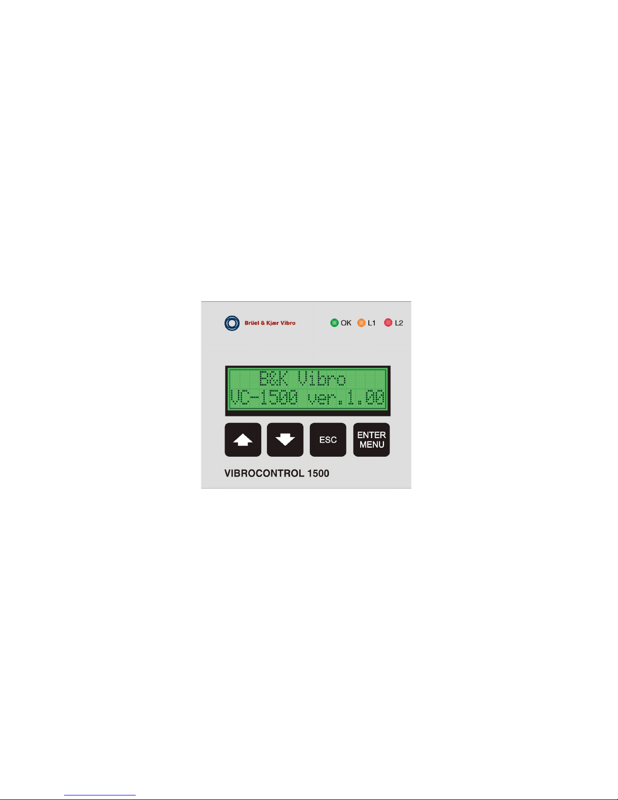
6.3 Hardware / Firmware version........................................................................28
7Operating the VIBROCONTROL 1500 ....................................... 29
7.1 Commissioning the instrument......................................................................29
7.2 Base display .................................................................................................29
7.3 Bargraph with limit value display...................................................................30
7.4 Measuring the temperatures.........................................................................30
7.5 Limit value violation - Display........................................................................31
7.6 Menu-guided instrument dialogue.................................................................31
7.7 Measuring the rolling-element bearing condition ..........................................32
7.7.1 Switching off the automatic reference value determination.....................................................35
7.7.2 General advice for bearing condition analysis.........................................................................36
7.8 Trend display and prognosis.........................................................................37
7.9 Rolling-element bearing condition and temperature - Trend.........................40
7.10 Frequency Analysis.......................................................................................41
7.11 Post-mortem display after a LIM2 violation...................................................42
7.12 Setting/Editing measurement channel functions - Channel ..........................43
7.12.1 Channel setup - (MONITOR) ..................................................................................................44
7.13 Setting up/Editing the basic functions - Device Setup ..................................50
8Error messages.......................................................................... 54
9Function checks and self-diagnosis............................................ 55
10 Accessories................................................................................ 56
10.1 Power supply AC-4111 .................................................................................56
10.2 AC-4601 power supply..................................................................................57
10.3 USB/CAN interfaceconverter AC-4201 .........................................................58
11 User dialogue - Overview ........................................................... 59
12 Calibration .................................................................................. 60
13 Disposal ..................................................................................... 60
14 CE Decleration and C-Tick......................................................... 61

Safety advice VIBROCONTROL 1500
VC1500EN / C103845.002 / V 09 / 14.04.2015 - 5 -
1 Safety advice
This operating instruction contains information and advice which must be
observed during the installation and operation of the VIBROCONTROL 1500.
Please read these operating instructions carefully before installing and taking
a VIBROCONTROL 1500 into operation!
Please read the general safety advice and grounding recommendations
before the installation and commissioning!
The safety advice and grounding recommendations are separately included
with the operating instructions!
Intended application
VIBROCONTROL 1500 is intended exclusively for measurement, display and
monitoring of bearing vibrations, rolling-element bearing condition and
temperature in the applications of machine protection and condition-
dependent machine maintenance.
Any application beyond these is considered as invalid for the system.
Reliability
VIBROCONTROL 1500 is equipment which is reliable in service and corresponds
to the state of the art technology. Every instrument leaves our works in an
error-free and safe condition.
Any person who is responsible for carrying out the installation and operation
of the instrument must have read and understood these operating
instructions and especially the safety advice in advance of the installation
and operation.
With inappropriate handling or non-observance of the operating instructions
the working reliability is not guaranteed.
Warning Note!
In the operating instructions reference is made to possible risks and
dangers with the installation and start-up. These references are
provided with the following terms:
Caution
A caution draws attention to the fact that in case of neglect of the
safety advice the possibility of material damage and personal injury
exists.
Commissioning tasks
Commissioning tasks may only be carried out by authorised and trained
technical personnel. The required authorisation is exclusively granted by
Brüel & Kjær Vibro.

VIBROCONTROL 1500 Overview
- 6 - VC1500EN / C103845.002 / V 09 / 14.04.2015
2 Overview
The VIBROCONTROL 1500 is a 2-channel, microprocessor-controlled
measurement data acquisition, monitoring and diagnosis instrument.
Constant-current powered (CCS) acceleration sensors are used for the
vibration measurements.
In addition to the measurement of casing vibrations in the frequency ranges
from 1/3/10 Hz to 1,000 Hz, a rolling-element bearing condition variable is
also calculated for the assessment of rolling-element bearing condition.
For the measurement and monitoring of temperatures, of type PT-100
temperature sensors may also be applied in addition to the vibration sensors.
For operation of the instrument a power supply of 18 to 36 VDC is necessary.
The power consumption of the instrument amounts to approx. 6 W.
2.1 Display and operating elements
Front view
Fig.1: VIBROCONTROL 1500 front view
Buttons and displays
, Buttons for switching to individual displays, making a selection within the
menus and entering values
ESC Button for return to previous display
ENTER
MENU
Button for confirmation of entry and calling up menus.
OK Green LED for display of the OK-status
L1 Amber LED for display of L1 status
L2 Red LED for display of the L2 status

Overview VIBROCONTROL 1500
VC1500EN / C103845.002 / V 09 / 14.04.2015 - 7 -
The standard equipment contains:
oTwo (2) relays with potential-free switch-over contacts for signaling event
messages. The relays are assigned to the set limit values.
oOne (1) OK relay with potential-free switch-over contacts for monitoring
of the power supply, the functions of the microprocessor system and the
connected sensors.
oTwo (2) analogue outputs proportional to the casing vibration.
oCAN-Bus interface for data transmission between the VIBROCONTROL
1500 and a super-ordinate computer.
All setting up tasks are carried out directly at the instrument by entry or
selection of parameter values. Setting up is also possible using the
VIBROCONTROL 1500 Control-Center-Software.
The connections for the power supply, measurement sensors, analogue and
contact outputs as well as the CAN-Bus interface are made through plug-in
terminal blocks.
2.2 Possible measurement and monitoring tasks
2.2.1 Display values
Corresponding to the national and international prescription for evaluation of
machine vibrations, the effective (RMS) value of vibration velocity is used for
display and monitoring.
Display value
Abbreviation
Unit
Vibration velocity
v
mm/s in/s
There is also the possibility to display and monitor the value of rolling-
element bearing condition; unit of rolling-element bearing condition: BC
(Bearing Condition)
Rolling-element bearing
condition
BC value BC
dimensionless
Measurement and monitoring of temperature is possible by connecting
PT-100 sensors.
Temperature
T
°C °F

VIBROCONTROL 1500 Overview
- 8 - VC1500EN / C103845.002 / V 09 / 14.04.2015
2.2.2 Measuring range limits
The measuring range can, according to the application, be adapted to the
machine or monitored plant by a wide range.
In the table below the measuring range limits (min. max.) are given
dependent upon the characteristic variable = effective (RMS) value of
vibration velocity.
Sensor : Vibration acceleration sensor
Variable : Effective value (RMS)
Display and monitor value
Measurement range
Unit
Min
Max
Vibration velocity 0 ... 10
0 ... 0.5
0 ... 200
0 ... 10
mm/s
in/s
For the selected measuring range, signals of 4 - 20 mA per sensor
proportional to the characteristic variable are available at the analogue
outputs.
2.2.3 Display value and bandwidth
Acquisition of the measured data is done by vibration acceleration sensors.
Display and monitor value Bandwidth of the
characteristic value
formation
Vibration velocity
1 Hz ... 1,000 Hz
3 Hz ... 1,000 Hz
10 Hz ... 1,000 Hz
Rolling-element bearing condition
500 ... 5,000 Hz DFT
2.2.4 Signal detection
The output voltage of the measurement sensors is proportional to the
measured magnitude of the time signal (vibration acceleration).
The following signal detection step is carried out by the VIBROCONTROL
1500:
Calculation of the effective (RMS) value of vibration velocity from an
integration of the vibration acceleration signal.

Overview VIBROCONTROL 1500
VC1500EN / C103845.002 / V 09 / 14.04.2015 - 9 -
2.3 General
Independently adjustable limit values are assigned to each measuring
channel for the casing vibrations, the rolling-element bearing condition and
the temperatures. The setting of the respective limit values is done in the unit
of the measurement channel.
Two values, which are adjustable over the entire measuring range, are
available for signaling a violation of the alarm limit settings. A limit value
violation is displayed at the VIBROCONTROL 1500 by means of LEDs and
the output of the violation respectively through potential-free relay contacts.
In order to prevent false alarms due to spurious, very short-term limit value
violations, a relay response lag time can be activated for each limit value of
the vibration.
The entry of the relay response lag time always take place in seconds units.
If a measured value exceeding the assigned limit value is sustained for
longer than the given response lag time, the appropriate event message is
activated.
If the current measured value falls below the limit value during the response
lag time, the event message "limit value violated" is deactivated and upon a
renewed limit value violation the response lag time count begins again.
2.4 Relay functions
VIBROCONTROL 1500 is equipped with a total of three (3) relays.
The status of these relays is signaled at the front panel by LED control
lamps. The relays are shared by both channels.
Note:
Short the reset contacts only for a short notice.
Caution
Voltages of a dangerous level may exist at the relay contacts at any
time!
LIM 1 relay
If the current measured value exceeds the set limit value for the RMS value
of vibration velocity L1v for longer than the period of the adjusted response
lag time T1, the LIM1 relay is activated (closed).
The same is valid - however without consideration of a response lag time -
during a violation of the limit value of the bearing condition L1BC and a
violation of the limit value of temperature L1temp (with the deployment of a
vibration sensor with PT-100 sensor or temperature sensor PT-100).
The LIM 1 relay is not self-latching and is immediately deactivated
(opened) if all L1v, L1BC or L1temp limit value is no longer violated.

VIBROCONTROL 1500 Overview
- 10 - VC1500EN / C103845.002 / V 09 / 14.04.2015
LIM 2 relay
If the current measured value violates the set limit value for the RMS value of
vibration velocity L2v for longer than the period of the adjusted response lag
time T2, the LIM2 relay is activated (closed).
The same is valid - however without consideration of a response lag time -
during a violation of the limit value of the bearing condition L2BC and a
violation of the limit value of temperature L2temp (with the deployment of a
vibration sensor with PT-100 sensor or temperature sensor PT-100).
The LIM 2 relay is self-latching. To reset this condition a reset of the relay
or an instrument reset must be carried out.
OK relay
Monitoring of the power supply, the functions of the microprocessor system
and the connected sensors is done by an OK-monitoring function. The
display of an existing OK fault is by means of an LED; the output of this
signal is by means of a set of potential-free switch-over contacts.
With an error-free operation the green LED at the instrument front panel
lights up (signaling operational readiness) and the contacts of the OK relay
are closed.
In case of a fault the LED is extinguished and the OK relay will be
deactivated.
This OK relay is active during error-free operation (closed, terminals 33 and
34 are connected). When a fault occurs these relay contacts open. This relay
is self-latching. To reactivate this, a reset of the relay or the instrument is
necessary.
Instrument Reset
Simultaneously pushing both of the buttons and ENTER/MENU for a
period of at least 3 seconds effects a reset and a restart of the instrument.
Reset of the self-latching relay
A reset of the active (closed) condition of the self-latching relays OK and
LIM2 is possible at the RESET input by connecting terminals 25 (RST REL2)
and 26 (GND). This reset simultaneously also deletes all error messages.
Note:
Short the reset contacts only for a short notice.

Technical Data VIBROCONTROL 1500
VC1500EN / C103845.002 / V 09 / 14.04.2015 - 11 -
3 Technical Data
Power supply 18 to 36 VDC
Current consumption 6 W + 0.25 W
Protection class IP 20
Housing Metal
Housing dimensions Appr. 90 x 115 x 75 mm (B x H x D)
Weight 700 g
Internal resistance 100 k
Ω
+ 10%
Instrument type 2-channel, switchable to 1-channel version
Measurement variable Vibration velocity mm/s or in/s
Measurement ranges 10; 20; 40; 50; 100; 200 mm/s or 0.5, 1; 2;
2.5; 5; 10 in/s
Signal detection Effective value (RMS)
Frequency ranges 1Hz to 1kHz, 3Hz to 1kHz, 10 Hz to 1kHz,
adjustable in the menu
Filter slope Acc. to ISO 2373
60 dB/decade with high pass 1/3/10 Hz
40 dB/decade with low pass 1 kHz
Limit values Adjustable with push buttons in menu
Alert alarm LIM 1 (arbitrary in selected measuring
range)
Danger alarm LIM 2 (arbitrary in selected measuring
range)
Cable connections:
Lower terminal row Divided terminal rows with terminal blocks,
plugged into the terminal sockets, max. 2.5
mm².
Upper terminal row Divided terminal rows with terminal blocks,
plugged into the terminal sockets,
0.14 mm
2
– 1.5 mm².
Power supply and
distribution terminal
1 mm2– 2,5 mm2
Cable glands of the
Protective housing
AC-211x
M12: 3.0 mm
2
– 6.5 mm
2
M16: 5.0 mm2– 10.0 mm2

VIBROCONTROL 1500 Technical Data
- 12 - VC1500EN / C103845.002 / V 09 / 14.04.2015
Sensor:
Sensor supply 5 mA ± 5%
Transmission factor 100 mV/g and OFF selectable in menu.
When selecting OFF in channel B, the
VIBROCONTROL 1500 operates as a 1-
channel instrument and the missing sensor
is then not interpreted as a fault!
Transmission factor
correction value
Multiplication factor = 0.5 to 1.99; value
adjustable in menu. For measurement
using acceleration sensors (CCS type)
whose transmission factor deviates from
the standard factor of 100 mV/g.
Analogue output 4…20 mA, for the RMS value of vibration
velocity of channel A and channel B,
proportional to the set measuring range.
Max. load at the analogue output < 500
Ω
.
Limit value outputs:
Potential-free contacts
Alert alarm Potential-free contacts LIM 1,
Display: amber LED
Danger alarm Potential-free contacts LIM 2,
Display: red LED
Contact loading: 5A/24 VDC, 5A/125 VAC, 5A/230 VAC
Upon violation of the limit value in channel
A or B, the corresponding relays LIM1 or
LIM 2 are activated.
OK monitoring Function test of the instrument and
connected sensors
Range of OK monitoring
6V + 0.5V ...18V + 0.5 V
Display Green LED, instrument OK and
operationally ready

Technical Data VIBROCONTROL 1500
VC1500EN / C103845.002 / V 09 / 14.04.2015 - 13 -
Latching function
of the relays:
OK
= self-latching
LIM 2 = self-latching
Upon violation of LIM 2 the relay is
activated and remains in this condition until
a RESET is carried out.
LIM 1 = not self-latching
If the measured value drops below the set
limit value, the LIM 1 relay activated by the
limit value violation is again deactivated.
Limit value monitoring Possible for vibration velocity, bearing
condition and temperature
Relay response lag time
0 to 10 sec., adjustable in menu
Analysis:
DFT analysis of the
bearing vibrations
Frequency range: 10 ...1,000 Hz
Sampling rate: 2,500 Hz
No. of samples: 800
No. of lines: 320
Nominal resolution: 3.125 Hz
Measurement and calculation time: appr.1.5
minutes
DFT analysis of bearing
condition
Frequency range: 500 ... 5,000 Hz
Sampling rate: 15,000 Hz
No. of samples: 800
No. of lines: 240
Nominal resolution: 18.75 Hz
Measurement and calculation time: appr. 5
seconds
In the upper display line the current three
highest values of vibration velocity in mm/s
or BC values are indicated. In the lower
display line the corresponding frequencies
belonging to these three values are
displayed.
Bearing condition value Effective value of acceleration in the
frequency band 500 Hz to 5 kHz. A relative
value of BC is calculated from this.
Trend measurement
with prognosis
possibility
For the time period of 10x8, 10x24 hours or
10x30 days, a statistical assessment of the
remaining time until the LIM 2 limit value will
be reached. The prognosis is only a guide
and is not guaranteed to be accurate.
Post-mortem A view of the measured bearing vibrations
in the time period 994 seconds before and
29 seconds after a LIM 2 violation.

VIBROCONTROL 1500 Technical Data
- 14 - VC1500EN / C103845.002 / V 09 / 14.04.2015
Logical inputs DC value:
Input logic, low VILmin = 0.0 V
VILmax = 1.6 V
Input logic, high VIHmi n= 2.5 V
VIHmax = 24.0 V
Maximum current
source
Ismax = 3 mA
Max. current loading for
+24 VDC supply for
logical inputs
40 mA
CAN-Bus
max. 40 instruments can be connected
Reset:
Reset at the instrument Simultaneously pushing the buttons and
MENU for at least 3 seconds effects a
reset of the instrument.
External reset Reset of the relays is possible by bridging
terminals 25 and 26 through the
VIBROCONTROL 1500 Control-Center-
Software
Accuracy:
Bearing vibration
measurement
at 80 Hz: ±2% ± 1digit
within the filter ranges 1/3/10… 1,000 Hz:
±10% ± 1digit
at the corner frequencies:
+10% -20% ± 1digit
Frequency response According to ISO 2373
60 dB/dec transition steepness 1/3/10 Hz
Filter 40 dB/dec transition steepness
1 kHz Filter
Rolling-element bearing
measurement BC
+10% -20% of measured value
Temperature: ± 2 °C in range 10 °C to 120 °C with
sensor AS-062/T1
Analogue outputs ±1% of the displayed value
±5% at 2 mA output current
DFT analysis of bearing vibration:
Frequency display in the
range 10 ... 1,000 Hz
± 2 Hz1
Amplitude display in the
selected filter range
+5% ... -20% of measured value
Overall vibration DFT
noise
+5% of measured value + 4 digits… for
10 Hz and 3 Hz highpass filter
+5% of measured value + 7 digits … for
1 Hz highpass filter
1Typical accuracy for a single sine-wave signal

Technical Data VIBROCONTROL 1500
VC1500EN / C103845.002 / V 09 / 14.04.2015 - 15 -
DFT analysis of rolling-element bearing condition:
Frequency display in the range
500 ... 5,000 Hz
± 18.75 Hz
Amplitude display in the range
500 ... 5,000 Hz
+10% ... -20% of measured value
BC DFT analysis noise +10% of measured value +4 digits … for
all highpass filters
BC DFT analysis channel
crosstalk
-40dB
Permissible ambient conditions
Storage temperature range
-20 °C ... +70 °C
Operating temperature
range without protective
housing AC-211x
0 °C ... +55 °C
Operating temperature
range in protective housing
AC-211x with 1 x
VIBROCONTROL 1500
0 °C ... +45 °C
Operating temperature
range in protective housing
AC-211x with 2 x
VIBROCONTROL 1500
0 °C … +40 °C
Humidity
max. 95% non-condensing
Sensors for vibration and rolling-element bearing condition:
Type Acceleration sensors with constant-
current power requirement (CCS
type),
transmission factor 100 mV/g
Temperature type PT-100, 3-wire
or PT-100 integrated in Acceleration
sensor
max. cable length between
VIBROCONTROL 1500 and
Sensor AS-062/T1
130 m
For monitoring the casing
vibration only
600 m
Standards conformity:
2006/95/EU Low-voltage
guideline
EN 61010-1 : 2002 - 08
2004/108 EU EMC guideline EN 61326-1: 2006 - 10
Use for industrial applications to
EN55011 Class A
WEEE-Reg.-Nr. DE
Product category /
Application area
69572330
9

VIBROCONTROL 1500 Installation
- 16 - VC1500EN / C103845.002 / V 09 / 14.04.2015
4 Installation
4.1 With the installation of the VIBROCONTROL 1500 the
following are to be observed:
•Installation must not be carried with the power connected!
•Installation and connections must be carried out only by technically
qualified personnel.
•The VIBROCONTROL 1500 is prepared for installation on a DIN rail.
•A minimum space of 5 cm above and below the instrument must be
maintained to guarantee sufficient air circulation.
•Depending upon the ambient temperature and loading of the instrument
the housing can tolerate higher temperatures!
•With establishment of the connections there is a danger of plugging the
connectors into the wrong socket; with a wrong connection the
instrument could be destroyed.
•Dangerous voltages may be connected at the relay contacts! - Danger of
electrocution!
•Recommended installation sequence:
oInstall the instrument on the DIN rail
oConnect the sensors
oConnect the relays and current outputs
oConnect the CAN-Bus, if applicable
oConnect the power
•Power should be connected only through isolating equipment, (a switch
or circuit-breaker)!
The switch or circuit-breaker used as an isolator must fulfill the
requirements according to IEC 60947-1 and IEC 60947-3 and be suitable
for the application.
Note:
The assembly of the VIBROCONTROL 1500 must not be undertaken in
areas with permanent vibrations. Possibly a vibration-isolated
installation must be implemented.

Installation VIBROCONTROL 1500
VC1500EN / C103845.002 / V 09 / 14.04.2015 - 17 -
Mounting in an AC-211x protective housing
The AC-211x protective housing offers mechanical protection as well as
protection against weather influences. Up to two VIBROCONTROL 1500
instruments plus an AC-4111 power supply can be mounted in the protective
housing.
Note:
Due to the limited air circulation there is a reduction in the permissible
operating temperature range:
1 x VIBROCONTROL 1500 + 1 x AC-4111: 0 °C …+45 °C
2 x VIBROCONTROL 1500 + 2 x AC-4111: 0 °C … +40 °C
Do not install any other components into the protective housing!
Note:
The connections between the VIBROCONTROL 1500 unit and the power
supply AC-4111 is already established. Remove the
VIBROCONTROL 1500 unit from the DIN Rail before mounting or
connecting other parts.
•Disconnect all Phoenix plugs in the lower terminal strip.
•Pull the black lever under Port LIM 1 and remove the
VIBROCONTROL 1500 unit from the DIN rail.
•Disconnect all Phoenix plugs in the upper terminal strip.
•Connect the new wiring and lay the cable screens carefully at the cable
glands.
How to mount the VIBROCONTROL 1500 unit into the protective
housing.
•Connect all upper Phoenix plugs at the VIBROCONTROL 1500 unit.
•Mount the VIBROCONTROL 1500 unit onto the DIN rail.
•Mount all lower Phoenix plugs at the VIBROCONTROL 1500 unit. Use a
screwdriver to do this carefully.
Fig.2: VIBROCONTROL 1500 unit mounted on a DIN trail
1. Upper terminal strip
2. DIN rail
3. Lower terminal strip

VIBROCONTROL 1500 Installation
- 18 - VC1500EN / C103845.002 / V 09 / 14.04.2015
4.1.1 Delivery specifications VIBROCONTROL 1500
unit in a protective housing AC-211x
The trim levels of the protective housing AC-211x with mounted Vibrocontrol
unit.
Fig.3: One VIBROCONTROL 1500 in protective housing.
(Order code: VIBROCONTROL 1500/01/DC)
Fig.4: One VIBROCONTROL 1500 unit with power supply in.
(Order code: VIBROCONTROL 1500/01/AC)

Installation VIBROCONTROL 1500
VC1500EN / C103845.002 / V 09 / 14.04.2015 - 19 -
Fig.5: Two VIBROCONTROL 1500 units in protective housing.
(Order code: VIBROCONTROL 1500/02/DC)
Fig.6: Two VIBROCONTROL 1500 units with power supply in protectiv
housing. (Order code: VIBROCONTROL 1500/02/AC)

VIBROCONTROL 1500 Connections
- 20 - VC1500EN / C103845.002 / V 09 / 14.04.2015
5 Connections
Upper terminal strip
Lower terminal strip
Fig. 7: VIBROCONTROL 1500 connection terminals
1st row
2nd row
Table of contents
Other Brüel & Kjær Vibro Measuring Instrument manuals
Popular Measuring Instrument manuals by other brands

SENSIT Technologies
SENSIT Technologies Trak-It IIIa Quick start instructions

Ebro
Ebro FOM 310 manual

Trident
Trident PD765 instruction manual

Watts Clever
Watts Clever EW4500 quick start guide

Hanna Instruments
Hanna Instruments HI98193 instruction manual

Burkert
Burkert 8222 ELEMENT NEUTRINO operating instructions

Nikon
Nikon XF SERIES quick start guide

Spectrum Technologies
Spectrum Technologies FieldScout TDR 250 product manual

Alesis
Alesis ADAT HD24 FirePort 1394 Service manual

Siemens
Siemens SITRANS F Additional operating instructions

OPTOKON
OPTOKON PM-800-GL instruction manual

BARTEC BENKE
BARTEC BENKE CFPP-4.2 operating instructions